


Small LiDAR Sensor for Robots and Drones: HM-LD1 Buying Guide
Small robots and drones need dependable 3D perception, but they rarely have unlimited room, payload capacity, electrical power, or computing headroom. A sensor that works well on a lab bench may be too heavy for a UAV. A lightweight module may fit the airframe but fall short on range, field of view, interfaces, or sunlight performance. Here’s the deal: choosing a small LiDAR sensor is not a matter of comparing the biggest range number on a product page.
The DTOF Solid State LiDAR HM-LD1 is built for embedded perception systems that need compact dimensions, low weight, real-time depth data, and flexible connectivity. The module measures approximately 43.5 mm × 30 mm × 26.5 mm, weighs 28 g, provides a 60° horizontal × 45° vertical field of view, and supports indoor ranging from 0.5–25 m and outdoor daytime ranging from approximately 0.2–8 m. This guide explains what those numbers mean in the real world, how dToF sensing works, and what engineers should verify before installing the sensor in a robot, drone, camera system, or embedded development platform.
Look at the HM-LD1 as one part of a complete perception stack, not as an isolated component. The sensor, mounting bracket, protective window, cable, processor, software, and control logic all affect the final result. A technically impressive module can still be the wrong choice if it cannot see the required area, cannot keep up with vehicle motion, or does not communicate cleanly with the host system.
Full LiDAR setups are powerful — but often too heavy, too complex, or just …
Table of Contents
- 👉 What Is a Small LiDAR Sensor?
- 👉 How a Small dToF LiDAR Sensor Works
- 👉 Why Size and Weight Matter in Robotics and UAVs
- 👉 HM-LD1 Specifications at a Glance
- 👉 Range, Accuracy, and Environmental Performance
- 👉 Field of View, Resolution, and Frame Rate
- 👉 Interfaces, SDKs, and Development Platforms
- 👉 Small LiDAR Sensor Applications for Robots
- 👉 Small LiDAR Sensor Applications for Drones
- 👉 Integration Checklist for OEMs and Developers
- 👉 Limitations and Buying Factors
- 👉 When HM-LD1 Is the Right Product
- 👉 Frequently Asked Questions
- 👉 Conclusion
What Is a Small LiDAR Sensor?
A small LiDAR sensor is a compact optical perception device that measures the distance between the module and objects in the surrounding environment. It emits light, detects the portion that returns from a target, and calculates distance from the measured travel time. Depending on the design, a LiDAR unit may provide one distance value, scan a single plane, or produce depth data across a two-dimensional or three-dimensional measurement area.
The HM-LD1 is more capable than a single-point ranging module. It is a compact solid-state depth-sensing unit based on SPAD direct time-of-flight technology. The module can deliver real-time depth images and 3D point-cloud data over a two-dimensional field of view. That makes it relevant to robotic navigation, obstacle avoidance, drone altitude sensing, smart inspection, camera assistance, presence detection, and embedded machine-vision development.
Small LiDAR versus other ranging technologies
Single-point time-of-flight sensors make sense when a system only needs to know the distance in one direction. A simple altitude sensor, for example, may only need to measure the distance between a drone and the ground. A scanning LiDAR adds angular information by sweeping a beam across a scene. A planar LiDAR maps a horizontal slice and can be very useful on a mobile robot that needs to understand walls, furniture, and open paths.
A compact 3D depth module takes a different approach. It observes a broader area and provides depth values across multiple measurement positions without relying on a large rotating assembly. Stereo cameras and structured-light cameras can also produce depth, but their performance depends heavily on visible texture, illumination, camera baseline, or projected patterns. Active dToF sensing can be useful when the scene has limited texture or when the system needs direct distance information in addition to ordinary image data.
That does not make LiDAR a universal replacement for cameras. Cameras generally provide much richer visual detail, color, and object-recognition information. LiDAR contributes geometric information, especially in situations where image appearance alone does not provide a reliable distance estimate. In the shop, engineers often get the best results by combining the two rather than forcing one sensor to do every job.
What “small” means in an engineering context
For an OEM or robotics developer, compactness has at least four dimensions: physical size, mass, power consumption, and integration complexity. The HM-LD1 weighs 28 g and consumes 1.2 W according to the supplied specifications. Those values matter just as much as the enclosure dimensions because the final product may also need a mounting bracket, cable, processing board, regulator, and protective optical window.
A suitable compact LiDAR sensor should fit the mechanical envelope, remain within the payload and energy budget, communicate with the selected controller, and deliver data quickly enough for the application’s control loop. It should also remain useful under the lighting, temperature, vibration, and target conditions expected in the field.

How a Small dToF LiDAR Sensor Works
The HM-LD1 uses direct time-of-flight, commonly abbreviated as dToF. The basic principle is simple: the module emits light, measures how long it takes for part of that light to return from a target, and converts the travel time into distance. The relationship is distance equals the speed of light multiplied by the round-trip travel time, divided by two. The division by two accounts for the light traveling to the target and then returning to the receiver.
In a working sensor, this process is repeated across an array or set of sensing positions. The device detects returned optical signals, calculates depth, and produces a valid value for each measurement position that meets the internal detection criteria. The host can then use those values to identify obstacles, estimate free space, calculate object distance, or create a point cloud for additional processing.
SPAD-based photon detection
SPAD stands for single-photon avalanche diode. At a high level, SPAD detectors are designed to detect very weak optical returns at the photon level. That sensitivity supports compact time-of-flight architectures because the receiver can identify the timing of returned light even when the optical return is relatively small.
SPAD dToF technology is not immune to the environment. Ambient sunlight, target reflectivity, surface angle, target geometry, optical contamination, and the distance between the sensor and object can all affect measurement quality. A responsible engineering evaluation should test the HM-LD1 against the materials and lighting conditions expected in the finished product instead of relying only on a controlled indoor demonstration.
Solid-state architecture
A solid-state LiDAR sensor is attractive for embedded applications because it avoids the need for a large mechanical scanning mechanism. That can reduce mechanical complexity, simplify packaging, and make the module easier to install inside a compact robot or UAV housing. It may also be easier to combine with cameras, inertial sensors, flight controllers, and edge-computing boards.
Solid-state design does not automatically mean unlimited outdoor range, complete sunlight immunity, or high-resolution imaging. Its main advantage is the combination of sensing capability and a relatively simple, compact form factor. The architecture still has to be matched to the project’s working distance, speed, field of view, and environmental conditions.
From measurement to depth data
The data path generally includes light emission, return-signal detection, time-of-flight calculation, depth generation, and output through the selected interface. HM-LD1 supports depth-image and point-cloud use cases, allowing the host processor to apply its own filtering, region-of-interest analysis, obstacle classification, or navigation logic.
Readers who want a broader physics overview can review the general concept of time-of-flight measurement. For robotics development, the practical point is that the sensor directly measures optical travel time instead of estimating distance solely from the appearance of an image.
Why Size and Weight Matter in Robotics and UAVs
Mechanical integration is often the first reason an engineering team starts looking for a miniature LiDAR sensor. A large unit may interfere with a robot’s protective shell, camera line of sight, suspension, gripper, or other payload. A smaller module can be mounted near the chassis, behind a suitable optical window, or beside an existing camera and IMU.
The stated HM-LD1 dimensions are approximately 43.5 mm × 30 mm × 26.5 mm, with a weight of 28 g. This compact housing can simplify installation in autonomous mobile robots with limited internal space. It can also be useful for drones, where the sensor, bracket, cable, protective housing, and processing hardware all count toward the aircraft’s payload.
Payload and flight endurance
For a UAV, every additional gram can influence motor load, battery consumption, flight endurance, dynamic response, and available payload capacity. The HM-LD1’s 28 g mass is an integration advantage, but it should not be presented as a guaranteed flight-time improvement. The actual effect depends on the aircraft, propellers, battery, flight profile, mounting arrangement, and onboard computer.
Use the sensor’s mass as an input to the aircraft design calculation. Do not stop there. Include the bracket, fasteners, cable, connector, vibration isolator, protective window, and any companion processor. The total installed payload is the number that matters during a real flight.
Power and thermal design
The specified power consumption is 1.2 W. That can fit within many embedded power budgets, but the complete electrical design still needs to account for supply voltage, startup behavior, cable losses, regulator efficiency, heat dissipation, and host-computer power. A sealed enclosure should also be reviewed for heat accumulation, particularly when the sensor operates continuously in a warm environment.
Compactness is valuable when it reduces the burden of the entire system, not simply when the sensor body is physically small. Engineers should evaluate the sensor and all associated integration hardware together.
HM-LD1 Specifications at a Glance
The DTOF Solid State LiDAR HM-LD1 is a small LiDAR module intended for robots, drones, cameras, security systems, and embedded development platforms. Its combination of dToF sensing, compact packaging, broad-angle coverage, and multiple interfaces supports both rapid prototyping and product-level integration.
| Specification | HM-LD1 Value |
|---|---|
| Dimensions | 43.5 mm × 30 mm × 26.5 mm |
| Indoor ranging capability | 0.5–25 m |
| Outdoor ranging capability | 0.2–8 m |
| Ranging accuracy | ±3 cm |
| Field of view | 60° horizontal × 45° vertical |
| Weight | 28 g |
| Resolution | 40 × 30 |
| Frame rate | 10 fps |
| Interfaces | UART / UDP / UVC |
| Operating temperature | −20 °C to 60 °C |
| Power consumption | 1.2 W |
The supplied product material also includes a separate marketing-copy dimension of 43.5 mm × 43.5 mm × 28.5 mm. That differs from the primary dimension value shown above. Before a production design or final technical publication, buyers should confirm the latest official dimension drawing and use the verified value for enclosure design, mounting, packaging, and procurement documentation. This is exactly the sort of discrepancy worth resolving before a bracket is machined or a plastic enclosure is sent to tooling.
The complete product information is available in the DTOF SSL HM-LD1 Product Brochure.
View Product Details & Pricing ➔
Range, Accuracy, and Environmental Performance
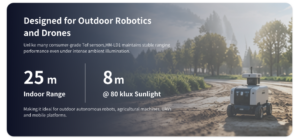
Range is one of the most visible specifications when comparing a small LiDAR sensor, but it should always be interpreted alongside lighting, target properties, field of view, accuracy, and application speed. HM-LD1 is specified for indoor ranging from 0.5–25 m and outdoor daytime ranging from approximately 0.2–8 m.
Indoor and nighttime ranging
The stated 0.5–25 m indoor or nighttime capability can support room-scale perception, warehouse robots, indoor inspection, obstacle detection, presence sensing, and navigation development. Controlled or low-light environments generally make optical ranging easier because the returned signal has less competition from ambient illumination. Even so, range is not the same thing as guaranteed accuracy for every object in the scene.
Target color, reflectivity, size, angle, and surface finish can influence the return signal. A large matte wall may behave differently from a narrow dark pole, a glossy panel, or a transparent surface. For autonomous robots, test representative obstacles rather than relying on a single laboratory target. If the robot will encounter black rubber, glass, polished metal, or thin structural members, put those materials on the test plan.
Outdoor daytime range
The specified outdoor daytime capability is approximately 0.2–8 m. The source material describes accurate measurement at 8 m on a clear summer day under assumed illumination of approximately 80,000 lux. Treat that as a stated test condition or example, not as a universal performance guarantee for every outdoor scene.
Direct sunlight, surface reflectivity, angle of incidence, object color, atmospheric conditions, and optical interference can affect measurement stability and maximum usable range. Drone and outdoor robot developers should test performance at the actual operating altitude or approach distance, including the strongest sunlight expected during operation.
Understanding ±3 cm accuracy
The HM-LD1 specifies ranging accuracy of ±3 cm. That is a useful figure for distance detection and local environmental perception, but the practical result depends on the conditions under which the measurement is made. Mounting vibration, sensor calibration, motion, target geometry, temperature, and host-side filtering can influence total system error.
Accuracy should also be separated from repeatability and detection probability. A sensor may produce a precise result when it sees a strong return, while a difficult target may produce an invalid or intermittent measurement. Production teams should define acceptable error, valid-data percentage, response time, and behavior during invalid readings.
Recommended validation protocol
In the shop, a useful validation program is straightforward and repeatable:
- ⚙️ Test the minimum working distance, typical operating distance, and maximum expected distance.
- ⚙️ Repeat the measurements at different lighting levels, including the strongest expected sunlight.
- ⚙️ Use targets with different colors, reflectivity, surface finishes, sizes, and approach angles.
- ⚙️ Compare stationary and moving targets while recording timestamps and invalid readings.
- ⚙️ Measure repeatability, detection probability, latency, and end-to-end system response.
- ⚙️ Repeat testing after the sensor reaches the expected operating temperature.
This process gives a more useful engineering result than comparing maximum-range figures in isolation. It also exposes problems early, when changing the mounting location or host software is still inexpensive.
Field of View, Resolution, and Frame Rate
HM-LD1 has a 60° horizontal × 45° vertical field of view. That gives the sensor a broad observation area for nearby obstacles, terrain, and environmental structure. A wide field of view can reduce blind areas in front of a robot or beneath a drone, although the mounting angle determines which portion of the scene is actually useful.
40 × 30 depth resolution
The 40 × 30 output contains 1,200 nominal measurement positions across the field of view. That is suitable for compact depth perception, obstacle-region detection, free-space estimation, object presence detection, altitude cues, and robotics experiments. It should not be described as equivalent to a high-resolution camera. The output is intended to provide spatial depth information, not detailed photographic imagery.
When the same number of measurement positions is spread across a wider field of view, each position covers a larger angular area. This can help detect broad obstacles, but it may make very narrow objects harder to identify. Developers should calculate the projected size of important objects at the planned operating distance. A thin pole that occupies only a small portion of one measurement area may require another sensor or a different mounting strategy.
10 fps operation
The specified frame rate is 10 fps, meaning the nominal interval between frames is approximately 100 milliseconds before communication and processing delays are included. That may be appropriate for many slow- to medium-speed robots, indoor navigation tasks, altitude sensing, and inspection workflows.
For a fast-moving platform, compare sensor rate with vehicle speed, stopping distance, control-loop frequency, processing latency, and communication delay. A 10 fps depth sensor may need to work with inertial data, odometry, cameras, or other sensors when the vehicle moves quickly. The sensor can still be useful, but the system should not assume that every new frame arrives in time to handle a rapidly changing hazard.
Interfaces, SDKs, and Development Platforms
One of the practical advantages of HM-LD1 is its support for UART, UDP, and UVC. Those interfaces allow the same small LiDAR module to be evaluated with embedded controllers, networked robotic computers, desktop development systems, and camera-like computer connections.
UART for embedded systems
UART is a practical choice for microcontrollers, flight controllers, and embedded robotic systems. It provides a direct serial connection with limited software overhead. Before designing a production cable or carrier board, confirm the baud rate, packet format, voltage levels, connector pinout, error-handling method, and timestamp behavior in the current documentation.
Also determine how the host identifies invalid data and whether the sensor reports a complete depth frame, individual measurements, or another packet structure. These details affect buffer sizing, scheduling, and the way the controller handles a missed or corrupted packet.
UDP for network-connected processing
UDP can support network-based development and distributed robotics. A sensor connected to an onboard computer can transmit data to another computer for visualization, logging, or processing. That can be convenient during prototyping because a PC or Linux workstation can handle visualization and analysis without placing every processing task on the robot.
UDP does not inherently guarantee delivery or ordering. Application software should therefore consider packet loss, frame timing, network congestion, synchronization, and recovery behavior. For safety-critical control, define what the robot or UAV does when depth data is delayed, duplicated, incomplete, or unavailable.
UVC for computer integration
UVC can simplify camera-like integration with compatible computers and operating systems. That may reduce custom driver work during early evaluation, subject to the supported operating system, output format, and software environment. UVC compatibility should still be checked on the exact host hardware and operating-system version intended for deployment. A device that enumerates correctly on a development laptop may need additional testing on an embedded Linux image.
SDKs and supported architectures
MRP offers SDKs for x86 Windows, x86 Linux, and ARM Linux. Those architectures cover common desktop computers, industrial PCs, Raspberry Pi systems, and embedded Linux platforms. The supplied technical support information also references ROS, OpenCV, Raspberry Pi, and Jetson integration assistance.
This support can help developers move from basic data capture to depth filtering, point-cloud visualization, obstacle detection, and application-specific control logic. It is still important to confirm the SDK version, installation process, sample code, operating-system support, and data representation before committing to a platform.
Small LiDAR Sensor Applications for Robots
A small LiDAR sensor for robots is useful when a vehicle needs local depth information but cannot accommodate a large scanning system. HM-LD1 can provide depth-image and point-cloud data for perception workflows that need more spatial information than a single-point distance sensor can provide.
Obstacle avoidance
A robot can analyze depth values to identify objects in front of its chassis and estimate whether a path is open. The 60° × 45° field of view can cover a useful forward area, while the 40 × 30 output supplies multiple depth positions for region-based analysis. A robust avoidance system should combine these measurements with robot dimensions, velocity, braking distance, steering limits, and control logic.
Do not treat a missing depth return as proof that the path is clear. The application should distinguish between valid far-distance data, an invalid measurement, a low-confidence return, and an object outside the sensor’s field of view. That distinction is important when the robot operates around dark objects, glass, or narrow obstacles.
Autonomous navigation
Compact depth data can support local navigation in corridors, rooms, warehouses, and inspection environments. A robot may use the sensor to estimate free space, detect a docking structure, identify a nearby wall, or maintain separation from obstacles. The module can act as one layer of a broader navigation system that may also include wheel odometry, an IMU, cameras, or a planar scanner.
SLAM development
HM-LD1’s point-cloud and depth-map output can contribute to LiDAR-assisted mapping and SLAM development. Final SLAM quality depends on much more than the sensor’s range. Time synchronization, motion distortion, frame rate, spatial resolution, IMU quality, odometry, calibration, and mapping software all affect the result.
For a slow indoor robot, 10 fps may be adequate for experimentation. For a faster platform or a scene with fine geometric detail, the development team should measure end-to-end latency and evaluate whether additional sensing is required. A proof-of-concept map that looks good in a quiet room does not automatically represent production performance.
Robotic vision and inspection
The module can support object presence detection, distance measurement, volume measurement, zone monitoring, camera autofocus, user presence detection, and object-recognition workflows. It can be used as a depth input alongside an RGB camera, allowing software to distinguish objects by both appearance and distance.
Teams comparing LiDAR and camera-based perception should consider the application’s lighting, texture, privacy, processing, and reliability requirements. Active depth sensing and camera-only perception solve overlapping but different problems.
For embedded prototyping, the HM-LD1 can also be evaluated alongside a compact controller or development platform such as the HM-RV1 RISC-V development board, subject to interface and software compatibility validation.
Small LiDAR Sensor Applications for Drones
Drones require sensors that are light enough for the aircraft while providing useful information at the required altitude and speed. HM-LD1 weighs 28 g and consumes 1.2 W, making it a candidate for payload-constrained UAVs, provided that the mounting hardware and processing computer are included in the complete payload analysis.
UAV altitude hold
A downward-facing depth sensor can measure the distance between the aircraft and the ground. That information can support low-altitude altitude hold, particularly in environments where other measurements may be affected by terrain, local conditions, or flight dynamics. The usefulness of the measurement depends on ground reflectivity, surface texture, illumination, aircraft motion, and sensor orientation.
A downward-facing unit may work well over a broad, solid surface but behave differently over vegetation, water, loose gravel, or a sharply changing surface. Test the actual flight environment. Also account for aircraft pitch and roll, because a sensor that is not pointed straight down may measure a slanted path rather than true vertical clearance.
Terrain following
Forward- or downward-facing ranging can provide clearance information over changing terrain. Developers should compare the HM-LD1 outdoor range with flight altitude, ground speed, terrain slope, sunlight, and required reaction time. A sensor with an 8 m stated outdoor daytime capability may suit some low-altitude applications but may be insufficient for a fast aircraft that needs a long look-ahead distance.
Drone obstacle avoidance
The 60° horizontal × 45° vertical field of view can help detect nearby obstacles within the sensor’s observation area. A single forward-facing module cannot observe every direction around an aircraft. Depending on the airframe and safety objectives, the design may require multiple sensors, a gimbal, a wider sensor arrangement, or sensor fusion with cameras and other ranging devices.
Payload and power analysis
Calculate total added mass by including the HM-LD1, mounting bracket, cables, connectors, protective housing, and host processor. Calculate the complete energy demand rather than using the sensor’s 1.2 W value alone. The aircraft’s battery, regulator, flight controller, companion computer, and communication equipment all contribute to power consumption and flight-time impact.
LiDAR provides local geometric information, while RTK positioning provides high-precision position information. These technologies solve different problems and can complement one another in UAV navigation, mapping, and inspection systems.
Integration Checklist for OEMs and Developers
Successful integration of a small LiDAR module requires more than connecting a cable and reading distance values. The mechanical, electrical, software, optical, and validation requirements should be reviewed before the product enclosure is finalized.
Mechanical design
Confirm the final dimension drawing, mounting-hole pattern, connector access, sensor orientation, field-of-view clearance, and protective-window design. The window material and thickness can influence optical performance. Keep structural parts, cables, brackets, and covers out of the sensing field of view.
For mobile robots, consider vibration from motors, wheels, gearboxes, and impacts. For UAVs, review vibration from propellers and the effect of mounting location on pitch, roll, and yaw motion. The sensor should be mounted securely without blocking airflow or creating unintended optical reflections.
Electrical design
Confirm input-voltage requirements, current margin, grounding, cable length, connector pinout, logic levels, electromagnetic compatibility, and regulator capacity. The supplied specifications identify power consumption as 1.2 W, but voltage and peak-current requirements should be obtained from the current brochure or integration documentation.
Plan for startup and shutdown behavior. A host computer may need to wait for the sensor to initialize before attempting to parse data. The design should also define how the application responds if the sensor disconnects, produces invalid measurements, or experiences a temporary communication interruption.
Software and data transport
Software planning should cover device discovery, driver or SDK installation, packet parsing, frame timestamps, coordinate conventions, invalid-measurement handling, startup behavior, shutdown behavior, logging, and firmware management. The output may need filtering before it is used by a navigation controller.
For UDP systems, define packet-loss handling and timing behavior. For UART systems, define buffer sizes, checksum validation, and recovery from corrupted packets. For UVC systems, test camera enumeration, resolution selection, frame capture, and compatibility with the intended host operating system.
ROS and OpenCV workflows
Depth data can be processed for thresholding, obstacle masks, point-cloud filtering, region-of-interest analysis, camera-LiDAR alignment, and navigation input. OpenCV may be used for image-based depth processing, while ROS-based systems may distribute sensor data among navigation, visualization, and control nodes.
Do not assume that every platform uses the same ROS package, message type, coordinate frame, or point-cloud convention. Confirm these details in the official SDK and sample applications. A short proof-of-concept should be completed before the hardware is integrated into a larger autonomy stack.
Calibration and validation
Validate depth offset, sensor orientation, coordinate-frame alignment, multi-sensor registration, temperature behavior, and motion performance. If HM-LD1 is used with a camera, calibrate the relative position and orientation between the two devices. If it is used with an IMU or odometry system, confirm timestamp alignment and frame conventions.
Platform selection
A microcontroller or flight controller may be suitable for simple UART-based distance processing. Raspberry Pi can provide a cost-effective Linux platform for prototypes, logging, and moderate perception tasks. Jetson platforms may be appropriate when the system combines depth sensing with accelerated computer vision or artificial intelligence. An x86 Windows or Linux computer is useful for development, visualization, and test automation.
Limitations and Buying Factors
A technically credible LiDAR buying guide has to discuss limitations as well as advantages. A compact module can be an excellent fit for one application and a poor choice for another. The decision should be based on measured performance under real operating conditions.
Outdoor sunlight
Outdoor daytime operation is more demanding than indoor operation because ambient light can interfere with optical detection. HM-LD1 is specified for approximately 0.2–8 m outdoors in daytime conditions, but the actual usable range depends on the scene. Test directly under the expected sunlight levels and at the target distances required by the vehicle.
Target reflectivity and geometry
Black, glossy, transparent, narrow, angled, or highly absorbent surfaces may produce weaker or less stable returns than broad, diffuse, reflective targets. A robot intended to operate around glass walls, dark furniture, metallic structures, or thin poles should include those objects in its validation program.
Resolution versus scene complexity
The 40 × 30 output is valuable for compact perception, but applications requiring dense mapping, fine object boundaries, or detailed three-dimensional reconstruction may need a higher-resolution sensor or sensor fusion. The correct question is whether the output is sufficient for the decisions the control and perception systems must make.
Frame rate versus vehicle speed
At 10 fps, the nominal frame interval is approximately 100 milliseconds before processing and communications latency are considered. During that time, a fast robot or drone may move a meaningful distance. Calculate stopping distance and obstacle-avoidance reaction time using the complete sensing and control pipeline.
Weather and enclosure effects
Rain, dust, condensation, optical contamination, vibration, and rapid temperature transitions may affect an installed sensor. The operating-temperature specification is −20 °C to 60 °C, but the final enclosure can create a different thermal environment. Protective windows should be tested for reflections, fogging, dirt accumulation, and mechanical stability.
Compliance and production requirements
Before volume deployment, buyers should request and verify operating and storage conditions, electromagnetic compatibility information, optical safety documentation, production test data, firmware-update procedures, warranty terms, lifecycle information, and supply-continuity planning. OEM and ODM projects may also require customized connectors, enclosure changes, firmware behavior, or application-specific technical support.
When HM-LD1 Is the Right Product
HM-LD1 is a strong candidate when a project needs a compact 3D depth sensor with low weight, indoor range up to 25 m, outdoor daytime ranging up to approximately 8 m, and stated ranging accuracy of ±3 cm under suitable conditions. Its 60° × 45° field of view, 40 × 30 output resolution, 10 fps frame rate, and UART, UDP, and UVC interfaces support a range of embedded perception applications.
It can be considered for autonomous mobile robots, UAV altitude hold, terrain following, nearby obstacle avoidance, SLAM development, smart inspection, camera autofocus, presence detection, object recognition, volume measurement, and zone intrusion monitoring. Support for x86 Windows, x86 Linux, and ARM Linux also provides flexibility during development and deployment.
HM-LD1 may not be the correct choice for long-range autonomous-driving perception, dense high-resolution mapping, high-speed flight requiring extremely low latency, or applications that have not validated performance in direct sunlight. It should also be evaluated carefully when the final design requires specifications not included in the current product documentation.
MRP’s stated capabilities include an independent R&D team, in-house manufacturing, technical integration support, customized product development, OEM/ODM services, and stable supply planning. These factors can matter to companies moving from a prototype to a repeatable production system. Buyers researching broader compact sensor solutions should compare verified specifications, documentation quality, support responsiveness, and production requirements rather than relying only on marketing claims.
Frequently Asked Questions
Can a small LiDAR sensor provide reliable outdoor measurements?
Is the sensor difficult to integrate with a robot, Raspberry Pi, or Jetson platform?
Is a compact LiDAR sensor suitable for drones and space-limited robots?
Conclusion
A suitable small LiDAR sensor must balance physical size, weight, range, accuracy, field of view, output resolution, frame rate, connectivity, power consumption, and environmental performance. HM-LD1 offers a practical combination for compact robotics and UAV systems, with a 28 g form factor, 1.2 W power consumption, 60° × 45° field of view, 40 × 30 depth output, 10 fps operation, and UART, UDP, and UVC interfaces. Its stated ranging capability reaches 0.5–25 m indoors and approximately 0.2–8 m outdoors in daytime conditions.
The final selection should be based on testing against actual target materials, lighting conditions, vehicle speed, mounting geometry, and software platform. Developers should download the product brochure, review interface documentation, confirm the official dimension drawing, and contact the supplier for technical validation, customization, OEM/ODM requirements, and production planning. The right sensor is the one that performs consistently in the finished machine, not merely the one with the most attractive specification sheet.
View the DTOF Solid State LiDAR HM-LD1 ➔
Download the HM-LD1 Product Brochure ➔
Request Your Trial Sample (Exclusive Discount Code Included)
Are you developing the next generation of autonomous mobile robots (AMRs), delivery drones,or smart automation systems? Whether you are a fast-growing startup, an established engineering firm, or leading a specialized robotics project, finding high-precision sensors that fit your budget shouldn’t be your biggest hurdle.
At MyRobotProject.com, we believe exceptional perception technology should be accessible to projects of every size. To help you accelerate your prototype development and field testing,we are opening an exclusive discount program for first-time sample orders of our dTOF Solid-State Lidar Sensors.
Why Choose Our dTOF Solid-State Lidar?
Direct Time-of-Flight (dTOF) solid-state technology offers the reliability, speed, and precision needed for high-performance spatial awareness without the mechanical wear-and-tear of traditional rotating Lidar sensors.
Decent Quality Under Budget: Premium-grade performance engineered to respect your Bill of Materials (BOM) constraints.
Solid-State Reliability: Built for long service life, shock resistance, and demanding operational environments.
Versatile Applications: Ideal for obstacle avoidance, precision hovering, mapping, and micro-navigation in robotics and drone platforms.
Claim Your First-Trial Sample Order Discount
We want to empower your development cycle right from day one. If you are ordering your very first trial sample, we are offering an exclusive online introductory discount tailored to your project scope.
How to Apply:
Send an Email to [email protected]
Include the Following Details:
Your Company / Firm Name (or Project Name)
Your Estimated Project Quantity / Target Volume
Mention that this is your very first trial order
Include Promo Code: MRP-202607 in your subject line or email body.
Fast-Track Guarantee: Our technical sales team will review your project details and respond with your customized discount quote in less than 24 hours.
Ready to Build?
Don’t let budget constraints slow down your technical validation. Reach out today with code MRP-202607 and let’s bring your robot or drone project to life!
📚 References & Further Reading
- Industry Standard: Time-of-flight measurement overview
- Related Guide: LiDAR and camera-based perception guide
- Product Resource: DTOF SSL HM-LD1 Product Brochure
- Embedded Platform: HM-RV1 RISC-V Development Board






