


How Does LiDAR Work? A Practical Guide to Time-of-Flight Sensing for Robots, Drones, and 3D Vision
LiDAR works by sending laser light into a scene, catching the reflected light that comes back, and using the round-trip travel time to calculate distance. That sounds simple until you remember one thing: light is moving brutally fast. A useful robot sensor has to measure tiny timing differences, reject noise, and still deliver distance data fast enough for a machine that may be rolling through a warehouse, flying near a bridge, or watching a restricted factory zone.
Here’s the deal: LiDAR is not just “a laser rangefinder.” In practical robotics and industrial automation, it becomes part of the machine’s spatial awareness. The sensor helps answer questions like: How far away is that pallet? Is there a person in the robot’s path? Is the drone too close to the ground? Is a bin full? Is a bridge surface within the inspection range? Those distance answers feed obstacle avoidance, mapping, navigation, inspection, safety detection, volume monitoring, and 3D machine vision.
This guide explains how LiDAR works from the ground up: how time-of-flight sensing measures distance, how a LiDAR module turns reflected light into depth maps and point clouds, why real-world accuracy depends on optics and timing electronics, and how engineers should compare specifications such as range, field of view, frame rate, resolution, power consumption, interfaces, software support, and environmental reliability. We will also look at practical industrial sensor choices, including the DTOF Solid State LiDAR HM-LD1 and the Stereo Vision Camera RoboBaton Mini, so you can see where LiDAR fits best and where stereo vision may complement it.
Got tired of bulky LiDAR setups for simple depth tasks
In the shop, the right answer is rarely “use LiDAR because LiDAR is advanced.” The right answer is usually tied to the job. A slow indoor inspection cart, a small UAV, a warehouse AMR, a machine-guarding sensor, and a 3D vision prototype all care about depth, but they do not all need the same range, resolution, enclosure, interface, or update rate. That is why understanding the sensing principle matters before choosing hardware.
Table of Contents
- 👉 What Is LiDAR?
- 👉 How Does LiDAR Work?
- 👉 What Time-of-Flight Means in LiDAR
- 👉 Direct ToF vs Indirect ToF LiDAR
- 👉 From Distance Measurements to 3D Point Clouds
- 👉 Key Components Inside a LiDAR Sensor
- 👉 What Affects LiDAR Accuracy?
- 👉 LiDAR for Robots, Drones, and 3D Vision
- 👉 LiDAR vs Stereo Vision
- 👉 Industrial Sensor Example: HM-LD1 and RoboBaton Mini
- 👉 Integration Considerations for Engineers
- 👉 LiDAR Selection Checklist
- 👉 FAQ: How Does LiDAR Work?
What Is LiDAR?
LiDAR stands for Light Detection and Ranging. It is an active sensing technology, meaning it creates its own measurement signal instead of depending only on light already in the environment. A normal camera records reflected visible light from the scene. LiDAR sends out controlled light, usually laser light, and analyzes what comes back. That active measurement is the reason LiDAR can be so useful in dark warehouses, low-texture corridors, machine safety zones, UAV landing areas, industrial inspection sites, and embedded robot systems where a plain image does not tell the whole story.
A LiDAR sensor can be built in several forms. Some modules measure one distance point. Others scan a line, sweep across a wider area, or capture a depth frame over a field of view. Depending on the design, the output may be a single range value, a 2D profile, a depth map, or a 3D point cloud. For robots and drones, that matters because machines need spatial information, not just pictures. They need to know how far away an object is, where it sits relative to the body of the machine, and whether it creates a motion or safety problem.
Modern solid-state LiDAR is especially helpful for compact robotics because it avoids bulky rotating mechanisms. Look, rotating scanners still have their place, especially in larger mapping systems, but compact solid-state modules are easier to package into small autonomous mobile robots, drones, inspection devices, smart monitoring platforms, and embedded 3D vision systems. Industrial positioning and navigation ecosystems are also supported by companies such as Bynav Technology and CHC Navigation. For teams combining LiDAR with visual positioning, see the VIO, VINS, and VSLAM troubleshooting guide.
How Does LiDAR Work?
The direct answer to “how does LiDAR work” is this: the sensor emits light, receives the reflection, measures the travel time, and calculates distance. The hard part is doing it reliably at speed. A robot may need to see people, pallets, black rubber wheels, metal racks, shelving, walls, glass panels, floor edges, and moving equipment. A drone may need to hold altitude, follow terrain, or avoid a structure during inspection. A factory monitoring system may need to know whether a restricted zone is occupied. LiDAR gives these systems distance data they can actually act on.
Step 1 — The LiDAR Emits Laser Light
A LiDAR transmitter emits laser pulses or modulated light toward the scene. In direct time-of-flight systems, the sensor sends short light pulses and waits for returning photons. The light may be projected as a point, line, pattern, or area depending on the optical design. In compact solid-state LiDAR modules, the optical system is designed to cover a defined field of view without relying on large mechanical rotation.
Step 2 — Light Reflects From Objects
When the emitted light reaches an object, part of it reflects back toward the sensor. The strength of that reflection depends on the object’s distance, color, reflectivity, angle, surface texture, and surrounding light conditions. A bright matte wall usually returns a stronger signal than black rubber. A surface facing the sensor directly usually returns more light than a sharply angled surface. Glossy, transparent, wet, or highly reflective materials can create more complicated returns, and that is where real-world testing earns its keep.
Step 3 — The Receiver Detects the Return
The receiver captures the reflected light. In advanced direct ToF architectures, sensitive detectors such as SPAD sensors can detect extremely weak photon returns. This matters because the reflected signal gets weaker as distance increases. Outdoor sunlight can also introduce background photons, so the receiver and signal processing must separate the useful laser return from noise. In practical terms, the receiver is not just “seeing light”; it is looking for the right light at the right time.
Step 4 — Timing Electronics Convert Flight Time Into Distance
The sensor measures the time between emission and return. Distance is calculated using the speed of light multiplied by time-of-flight, divided by two. The division by two is necessary because the light travels to the target and then back to the receiver. In real products, LiDAR distance measurement depends on precise timing, calibrated optics, stable electronics, and algorithms that filter unreliable returns.
For robot obstacle avoidance, the system does not always need a detailed color image of an obstacle. It needs to know that an obstacle exists, how far away it is, where it sits in the sensor’s field of view, and whether the robot should slow down, stop, or re-plan its path. That is why time-of-flight LiDAR, dToF LiDAR modules, and 3D depth sensing are widely used in robotics, UAVs, industrial automation, and embedded perception systems.
What Time-of-Flight Means in LiDAR
Time-of-flight means measuring how long it takes for light to travel from the sensor to a target and back again. In everyday language, that sounds easy. In engineering, it is a serious timing problem because light travels at about 300,000 kilometers per second. A difference of only a few centimeters corresponds to an extremely small time difference. That is why LiDAR sensors need specialized emitters, detectors, timing circuits, optical filters, calibration routines, and signal-processing algorithms.
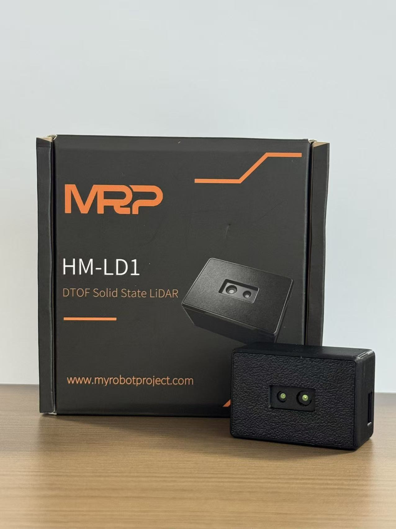
Direct time-of-flight, often shortened to dToF, measures the actual travel time of a laser pulse. The transmitter emits a pulse, the receiver detects the return, and the electronics estimate distance from that time interval. This architecture is well suited to compact depth sensors that need accurate distance measurement. Modules such as the DTOF Solid State LiDAR HM-LD1 use SPAD dToF technology to generate real-time depth images and 3D point cloud data for robotics, inspection, distance detection, autonomous navigation, and embedded vision development.
Timing quality matters because a LiDAR sensor is only as reliable as its weakest measurement stage. Timing jitter can blur distance precision. Detector sensitivity affects how well the receiver captures weak returns. Optical design affects field of view, signal collection, and stray light rejection. Ambient light rejection is essential for outdoor use. Calibration compensates for sensor offsets, optical geometry, temperature effects, and signal behavior. In industrial systems, the final depth output is not just raw physics; it is hardware and software working together under field conditions.
Direct ToF vs Indirect ToF LiDAR
Direct ToF and indirect ToF are both time-of-flight methods, but they estimate distance differently. Direct ToF measures the actual round-trip time of laser pulses. It is often selected when engineers need accurate range measurement, longer distance potential, and robust distance output from a compact sensor. The tradeoff is that direct ToF requires precise timing electronics, sensitive detection, careful calibration, and reliable processing.
Indirect ToF generally uses modulated light and measures phase shift between the emitted and reflected signal. This method can work well in short-range depth cameras and compact imaging systems. However, depending on modulation frequency and system design, indirect ToF may face ambiguity, multipath effects, or range limits. It is not automatically worse or better than direct ToF. It is simply built around different design priorities.
For robots and drones, the right choice depends on the operating environment. dToF is often attractive where compact size, distance accuracy, outdoor adaptability, and direct range measurement matter. iToF may be useful for short-range indoor depth imaging where the scene and range are controlled. Engineers should compare range, power consumption, resolution, field of view, frame rate, sunlight tolerance, interface options, SDK support, and processing requirements instead of choosing based only on the technology label.
| Technology | How It Measures Distance | Typical Strengths | Common Considerations |
|---|---|---|---|
| Direct ToF LiDAR | Measures the actual round-trip time of laser pulses | Accurate ranging, longer distance potential, robust depth measurement | Requires precise timing electronics and signal processing |
| Indirect ToF LiDAR | Measures phase shift of modulated light | Useful for compact depth cameras and short-range sensing | May face ambiguity, multipath, or range limitations depending on design |
From Distance Measurements to 3D Point Clouds
A single LiDAR measurement tells the system how far away one part of the scene is. A depth sensor becomes much more useful when many measurements are organized into spatial data. One common output is a depth map. A depth map is similar to an image, but each pixel stores distance instead of color. If a LiDAR module outputs a 40 × 30 depth frame, that frame contains 1,200 distance points. That can be enough for obstacle awareness, zone monitoring, shape approximation, distance triggering, and compact robot perception.
A point cloud takes depth data one step further by converting each distance reading into a 3D coordinate. Each point may represent a wall, shelf, person, pallet, bridge surface, floor area, terrain feature, or industrial object. Robots and drones use point clouds for mapping, navigation, SLAM, collision avoidance, inspection, measurement, and environment understanding. The density of the point cloud depends on the sensor resolution, field of view, range, frame rate, and software pipeline.
Frame rate matters when the sensor or target is moving. A stationary inspection system can often work with a slower update rate than a fast mobile robot. A 10 fps depth output may be sufficient for many obstacle detection, inspection, and monitoring tasks, but the correct frame rate depends on vehicle speed, stopping distance, processing latency, safety margin, and the type of objects being detected. In the shop, you evaluate the full perception loop, not just the number printed on a datasheet.
Suggested visual: LiDAR time-of-flight ranging principle diagram showing emitted laser light and reflected return signal. LiDAR distance measurement is based on laser emission, reflected light detection, and time-of-flight calculation.
Need compact depth sensing for a robot or drone? Explore the DTOF Solid State LiDAR HM-LD1 for real-time depth images and 3D point cloud output.
Key Components Inside a LiDAR Sensor
Laser Emitter
The laser emitter creates the light used for distance measurement. Important design factors include pulse timing, optical efficiency, beam shape, power management, and eye safety. The supplied product data does not specify wavelength, so a correct engineering review should not assume one. Engineers should confirm wavelength, safety classification, optical output, and mounting requirements through the official brochure or technical documentation before deployment.
Receiver and Detector
The receiver collects reflected light. In direct ToF systems, sensitive detectors are important because returned signals can be weak, especially at longer distance or under bright ambient light. SPAD sensors are valuable in dToF architectures because they can detect very low light levels and extremely fast events. Still, the detector is only one part of the system. Detector performance has to be matched with optics, filtering, firmware, thermal behavior, and signal processing.
Optics and Field of View
The optical design determines how the sensor sees the world. A wide field of view captures more of the environment, which is useful for obstacle awareness and zone detection. However, if resolution is limited, a wider field of view can reduce angular density. Engineers need to match field of view to the application: forward-facing obstacle detection, downward altitude measurement, side monitoring, doorway detection, shelf inspection, or area safety monitoring.
Timing Circuitry
The timing circuit measures the delay between pulse emission and return detection. This is central to LiDAR accuracy. Even if the optical design is strong, poor timing stability can reduce distance quality. Timing circuitry must work with calibration data, temperature compensation, and filtering algorithms to deliver stable results. When the machine is vibrating, heating up, cooling down, or seeing mixed surfaces, that stability becomes even more important.
Processing Algorithm
LiDAR processing may include noise reduction, confidence scoring, ambient light suppression, multi-return handling, filtering, calibration compensation, and conversion to depth maps or point clouds. In real products, the user usually receives processed data rather than raw photon events. This makes software support, SDK availability, sample tools, documentation, and operating-system compatibility important for integration.
Output Interface
Sensor data must reach the host controller. Common interface paths include UART, UDP, UVC, USB, Ethernet, ROS middleware, HTTP, and custom SDKs. The HM-LD1 supports UART, UDP, and UVC, while the RoboBaton Mini supports Type-C and UART with HTTP and ROS2 transport options. Interface choice affects latency, bandwidth, wiring, host compatibility, development effort, and long-term maintainability.
What Affects LiDAR Accuracy?
LiDAR accuracy depends on more than the time-of-flight formula. Out in the field, measurement quality is affected by distance, target surface, sunlight, field of view, resolution, temperature, mechanical stability, calibration, and algorithms. A sensor that looks clean on a bench may behave differently on a vibrating robot, inside a dusty plant, or under hard sunlight. That is not a knock on the sensor. That is normal industrial reality.
Distance and Signal Strength
The farther the target, the weaker the reflected signal. This is why compact LiDAR modules often list separate indoor and outdoor ranges. Indoor environments usually have lower background light, while outdoor sunlight increases receiver noise. The HM-LD1 lists indoor ranging from 0.5–25 m and outdoor ranging from 0.2–8 m, which helps engineers estimate where the module fits best.
Surface Reflectivity
Surface material changes return strength. Bright matte targets are usually easier to detect than dark absorbent materials. Glass, shiny metal, water, angled panels, and highly reflective surfaces may produce weaker, distorted, or unexpected returns. For industrial robots, validation should include the real materials found on site, such as rubber tires, painted metal, packaging film, concrete, glass partitions, polished floors, and wet surfaces.
Ambient Light
Sunlight introduces background photons into the receiver. A good LiDAR module uses optical filtering, timing gates, signal processing, and calibration to identify the useful return signal. Outdoor performance should be tested in direct sunlight, cloudy conditions, shadows, high-lux scenes, and mixed lighting. The HM-LD1 product details mention useful outdoor measurement up to 8 meters on a clear summer day assuming 80,000 lux.
Field of View and Resolution
Resolution affects how much detail the sensor can observe. The HM-LD1 has 40 × 30 resolution, meaning it outputs a grid of depth points. This can be useful for compact perception tasks, zone detection, and obstacle awareness, but engineers should match resolution to the smallest object that must be detected at the required distance. A small obstacle far away may occupy only a few depth cells, and that can change detection reliability.
Mechanical and Thermal Stability
Temperature changes can affect optics, electronics, timing, and calibration. Industrial systems should consider the expected operating temperature range, mounting material, vibration, airflow, enclosure design, protective windows, and long-term stability. The HM-LD1 supports -20 ℃ to 60 ℃ operation, which is important for robots and embedded devices used in warehouses, outdoor inspection, and mobile platforms.
Calibration and Algorithms
Raw ToF measurements are not the final product. Calibration compensates for offsets, optical geometry, temperature effects, and signal characteristics. Algorithms improve reliability through filtering and confidence evaluation. For vision-based localization challenges that often appear in robot navigation stacks, see Explore Visual Inertial Odometry Issues.
LiDAR for Robots, Drones, and 3D Vision
Robot Obstacle Avoidance
Robots use LiDAR to detect objects before collision. Autonomous mobile robots, delivery robots, inspection robots, and service robots may need to detect people, pallets, walls, shelving, machinery, cables, low obstacles, and unexpected objects in the path. A LiDAR depth map can help the control system identify whether the route is clear, whether the robot should slow down, or whether a new path is required.
SLAM and Mapping
LiDAR can contribute to simultaneous localization and mapping by identifying scene geometry. High-density LiDAR is often used for detailed mapping, while compact solid-state LiDAR may focus on local depth perception, obstacle awareness, and complementary spatial input. In many systems, LiDAR is fused with wheel odometry, IMU data, stereo vision, visual-inertial odometry, GNSS, or other sensors to improve reliability.
UAV Altitude Hold and Terrain Following
Drones can use downward-facing or forward-facing LiDAR to estimate distance to the ground, terrain, walls, roofs, bridges, towers, or other structures. This supports altitude hold, landing assistance, terrain following, low-altitude inspection, and obstacle avoidance. Weight and power are critical in UAV design, which is why compact modules such as the HM-LD1, with 28 g weight and 1.2 W power consumption, are relevant for embedded aerial applications.
Industrial Inspection
LiDAR can measure distance to objects that are difficult, slow, or unsafe for people to approach. The HM-LD1 product description mentions use cases such as bridges, expressways, and dams. In industrial navigation and positioning ecosystems, suppliers such as Bynav Technology and CHC Navigation are part of the broader landscape of technologies used for machine autonomy, mapping, and positioning.
Volume Measurement and Zone Monitoring
Depth maps can support volume estimation, bin monitoring, object presence detection, intrusion detection, and restricted-zone monitoring. For example, a sensor may detect whether a container is filling, whether a pallet occupies a loading area, whether a person enters a danger zone, or whether an object has moved into a robot’s working envelope. In these cases, reliable distance is often more important than high-resolution color imaging.
LiDAR vs Stereo Vision
LiDAR and stereo vision both help machines understand 3D space, but they work differently. LiDAR is an active sensor. It emits light and measures the return. Stereo vision is usually passive. It uses two cameras separated by a baseline and estimates depth by comparing differences between the left and right images. This difference is called disparity. When the camera calibration and scene texture are good, stereo vision can produce rich spatial information while also providing visual context.
LiDAR is strong when direct distance measurement is needed. It can work on surfaces that have little visual texture, and it can provide depth in low-light or nighttime conditions depending on the sensor design. It is useful for obstacle detection, range measurement, zone monitoring, and compact 3D sensing. Stereo vision is strong when the system also needs image detail, wide visual perception, localization, visual odometry, trajectory tracking, and scene understanding.
The RoboBaton Mini stereo vision camera represents this complementary approach. It uses dual fisheye global shutter imaging, 640 × 480 resolution at 40 fps, a 60 mm baseline, IP68 ingress protection, Type-C and UART interfaces, HTTP and ROS2 transport protocol support, Windows and Linux support, and 200 Hz algorithm output / IMU. These specifications make it relevant for robot navigation, UAV navigation, GPS-denied localization, visual odometry, embedded perception, and trajectory tracking.
Many autonomous systems benefit from combining LiDAR and stereo vision instead of treating them as competitors. LiDAR can provide reliable distance cues and obstacle geometry. Stereo vision can provide visual context and motion estimation. Together, they can support robust navigation, mapping, and perception in warehouses, tunnels, industrial spaces, inspection corridors, UAV applications, and embedded robotics. Developers troubleshooting visual localization can also review the Help Center for integration resources.
Industrial Sensor Example: HM-LD1 and RoboBaton Mini
Understanding how LiDAR works becomes more useful when you compare real sensor specifications. The DTOF Solid State LiDAR HM-LD1 is a compact dToF LiDAR module for depth imaging and 3D point cloud output, while the RoboBaton Mini is a stereo vision camera designed for visual depth perception, localization, and embedded robotics. The two products represent different approaches to spatial perception: active time-of-flight sensing and passive stereo vision.
DTOF Solid State LiDAR HM-LD1
The DTOF Solid State LiDAR HM-LD1 is a solid-state LiDAR module based on SPAD dToF technology. It delivers real-time depth images and 3D point cloud data for accurate environmental perception. It supports indoor or nighttime ranging up to 25 m and outdoor daytime ranging up to 8 m according to the supplied product details. It is designed for obstacle avoidance, distance detection, autonomous navigation, smart inspection, robotic vision development, UAV altitude hold, terrain following, autofocus, user presence detection, object recognition, volume measurement, and zone intrusion monitoring.
With UART, UDP, and UVC interfaces, the HM-LD1 can be integrated with PCs, Raspberry Pi, flight controllers, and embedded platforms. MRP also offers SDKs for x86 Windows, x86 Linux, and ARM Linux, supporting development across operating systems and architectures. Its compact size and 28 g weight make it suitable for autonomous mobile robots with limited sensor space and drones where payload affects flight time.
| HM-LD1 Specification | Real Product Detail |
|---|---|
| Product Name | DTOF Solid State LiDAR HM-LD1 |
| Product URL | https://myrobotproject.com/product/dtof-solid-state-lidar-hm-ld1/ |
| Download | DTOF SSL HM-LD1 Product Brochure |
| Dimensions | 43.5 mm × 30 mm × 26.5 mm |
| Ranging Capability | Indoor: 0.5–25 m; Outdoor: 0.2–8 m |
| Ranging Accuracy | ±3 cm |
| Field of View | 60° horizontal × 45° vertical |
| Weight | 28 g |
| Resolution | 40 × 30 |
| Frame Rate | 10 fps |
| Interface | UART / UDP / UVC |
| Operating Temperature | -20 ℃ to 60 ℃ |
| Power Consumption | 1.2 W |
| Output | Real-time depth images and 3D point cloud data |
| Platform Support | SDKs for x86 Windows, x86 Linux, and ARM Linux |
View Product Details & Pricing ➔
Integration Considerations for Engineers
Choose the Right Interface
Interface selection affects development speed and system architecture. UART can be simple for embedded control and low-bandwidth distance data. UDP may be better when depth data is sent over a networked architecture. UVC can simplify PC-based development because it aligns with common camera-style workflows. Type-C can be practical for compact modules and development kits. HTTP and ROS2 are useful for robotics middleware, distributed systems, and integration with perception stacks.
Match Sensor Output to the Compute Platform
A sensor should match the compute platform’s bandwidth, processing capacity, operating system, and software stack. HM-LD1 supports SDKs for x86 Windows, x86 Linux, and ARM Linux, which is valuable for PCs, Raspberry Pi-class systems, embedded Linux devices, and development platforms. RoboBaton Mini supports Windows and Linux and includes HTTP / ROS2 transport support, making it relevant for robotics teams that build around ROS2 nodes and visual navigation pipelines.
Consider Mounting and Alignment
Mounting angle determines what the sensor can actually observe. A forward-facing LiDAR may detect obstacles in the travel path. A downward-facing LiDAR may support altitude hold, floor tracking, or terrain following. A side-facing sensor may monitor clearance near shelves, walls, or equipment. Engineers should consider blind zones, cable strain relief, vibration isolation, protective windows, field of view overlap, and calibration after mounting.
Plan for Environmental Conditions
Indoor, outdoor, high-lux sunlight, dust, vibration, temperature, and moisture all matter. HM-LD1 supports outdoor daytime ranging up to 8 m and -20 ℃ to 60 ℃ operation. RoboBaton Mini has IP68 ingress protection and is described as maintaining precise calibration under extreme temperatures. For outdoor robots or drones, validation should include bright sunlight, shadows, rain protection, vibration, heat, cold, and the real materials the sensor will face.
Validate With Real Scenes
Datasheet values help with selection, but field testing proves whether the system works. Engineers should test against dark objects, reflective surfaces, glass, angled surfaces, moving targets, low-texture walls, sunlight, dust, vibration, and operating temperature extremes. The validation process should include latency, data loss, false positives, missed detections, calibration drift, processing load, and how the robot behaves when confidence is low.
LiDAR Selection Checklist
Choosing a LiDAR module should begin with the application, not the sensor brand. A UAV altitude sensor, a robot obstacle detector, a bin monitoring device, and an industrial inspection tool may all need depth data, but they do not need the same field of view, resolution, range, update rate, or enclosure strategy. Use the checklist below before final selection.
- ✅ Range: Does the sensor support the required indoor and outdoor distance?
- ✅ Accuracy: Is the error tolerance acceptable for obstacle avoidance, mapping, or measurement?
- ✅ Field of View: Does the FOV cover the required detection zone?
- ✅ Resolution: Is the depth grid dense enough for the smallest target object?
- ✅ Frame Rate: Is the update rate fast enough for robot speed and stopping distance?
- ✅ Power: Can the robot or drone power budget support the module?
- ✅ Weight: Is the sensor light enough for UAV or compact robot integration?
- ✅ Interface: Does it support UART, UDP, UVC, USB, ROS2, or the required SDK?
- ✅ Environment: Can it operate in expected temperature, sunlight, dust, vibration, and moisture conditions?
- ✅ Software: Are SDKs, drivers, documentation, and sample data available?
Need help selecting a depth sensor for a robot, drone, inspection platform, or embedded vision project? Compare the HM-LD1 dToF LiDAR and RoboBaton Mini stereo vision camera, or contact the MyRobotProject team for integration support.
FAQ: How Does LiDAR Work?
How does LiDAR actually measure distance so accurately?
How do LiDAR sensors capture such tiny light travel times?
What is LiDAR useful for beyond phones and AR?
Is LiDAR better than a camera for robot navigation?
What specifications matter most when choosing a LiDAR module?
Can LiDAR work outdoors in sunlight?
What is the difference between a depth map and a point cloud?
When should a robot use both LiDAR and stereo vision?
Building a robot, UAV, inspection device, or embedded 3D vision system? Contact MyRobotProject to compare LiDAR, stereo vision, and positioning modules for your application.
📚 References & Further Reading
- Industry Standard: Bynav Technology
- Industry Navigation Supplier: CHC Navigation
- Related Guide: VIO, VINS, and VSLAM Troubleshooting Guide
- Related Guide: Explore Visual Inertial Odometry Issues
- Support Resource: MyRobotProject Help Center
- Product Reference: DTOF Solid State LiDAR HM-LD1
- Product Reference: Stereo Vision Camera RoboBaton Mini






