


dToF LiDAR for Robotics: Compact 3D Sensing Modules for Navigation, Obstacle Avoidance & Embedded Vision
Here’s the deal: modern robots are being asked to work in tighter, busier, and less predictable spaces than most legacy sensor stacks were built for. Autonomous mobile robots, service robots, drones, inspection platforms, smart cameras, and low-profile robot vacuums all need dependable depth perception. But every sensing method brings trade-offs. Mechanical LiDAR can add height, cost, and moving parts. Stereo cameras can get confused by blank walls, poor lighting, or repeating warehouse patterns. Basic proximity sensors may tell you something is nearby, but they usually do not give enough 3D structure for real navigation. That is exactly where dtof lidar earns its keep. By directly measuring how long emitted light takes to return from nearby surfaces, compact dToF LiDAR modules can generate depth maps and point cloud data in real time, giving embedded systems a practical way to understand distance, shape, and spatial layout.
For robotics engineers and product teams, the real question is not just “Do we need LiDAR?” anymore. It is “What kind of LiDAR actually fits our mechanical envelope, compute platform, cost target, power budget, and perception stack?” A compact solid-state dToF LiDAR module such as the DTOF Solid state LiDAR HM-LD1 gives teams a practical bridge between serious 3D sensing and embedded deployment. With a small form factor, 40×30 depth resolution, 10 fps frame rate, UART/UDP/UVC interfaces, and indoor ranging up to 25 m, it is built for navigation, obstacle avoidance, SLAM support, presence detection, inspection, and embedded vision development across robots, UAVs, cameras, and intelligent sensing systems.
Table of Contents
- 👉 What Is dToF LiDAR?
- 👉 How dToF LiDAR Works
- 👉 dToF vs iToF vs Structured Light vs Stereo Vision
- 👉 Why dToF LiDAR Matters for Robotics
- 👉 dToF LiDAR for Navigation, Obstacle Avoidance & SLAM
- 👉 Embedded Vision Integration: UART, UDP, UVC, SDKs & ROS
- 👉 Product Showcase: DTOF Solid State LiDAR HM-LD1
- 👉 Application Scenarios for dToF LiDAR Modules
- 👉 How to Select a dToF LiDAR Module
- 👉 Deployment Best Practices for Robotics Engineers
- 👉 dToF LiDAR FAQ
- 👉 Conclusion: Building Compact Robots with 3D Perception
What Is dToF LiDAR?
dToF LiDAR means direct Time-of-Flight Light Detection and Ranging. In plain shop-floor language, the module sends out short pulses of light and measures how long it takes for the reflected photons to come back. Since the speed of light is known, the system can calculate distance from the measured round-trip time. For a broader technical overview of LiDAR technology, see the LiDAR overview on Wikipedia.
Look, in industrial robotics, dToF LiDAR should not be treated like a simple “distance sensor.” A single-point distance sensor can tell a robot that something exists at one spot. A dToF LiDAR depth module can provide spatial information across a field of view. Depending on the sensor architecture and firmware output, that information may include distance measurements, depth maps, 3D point clouds, obstacle zones, object presence, and region-based detection data. That difference matters when a robot needs to move intelligently instead of just slamming on the brakes when one threshold is crossed.
The value of dtof lidar is especially clear in applications where robots must understand space without relying on visual texture. A stereo camera may have trouble with a plain white wall, a dark corridor, or repetitive warehouse racking. A dToF module uses active illumination, so it measures distance by sending light into the scene and detecting the returned signal. That makes it useful for compact 3D perception, approach detection, docking, obstacle avoidance, user presence detection, UAV altitude sensing, terrain following, volume estimation, and intelligent camera triggering.
In embedded robotics, dToF LiDAR also gives engineering teams a practical integration advantage. A module that outputs a depth image or point cloud can be connected to a robot controller, onboard computer, Raspberry Pi-class board, embedded Linux platform, flight controller, or industrial PC. Instead of building optical ranging hardware from scratch, product teams can evaluate a compact module and spend their engineering time on mechanical integration, perception algorithms, safety logic, and system-level behavior.
How dToF LiDAR Works
Photon Emission and Return Timing
A dToF LiDAR module emits short pulses of light toward the environment. When those photons hit a surface, some portion of the light reflects back toward the receiver. The sensor measures the time interval between the outgoing pulse and the detected return. This happens extremely fast, so the timing electronics, receiver design, optics, calibration, and signal processing all matter. In the shop, this is where the difference between a decent sensor and a frustrating one usually shows up.
Unlike passive vision systems that infer depth from image geometry, dToF LiDAR actively measures distance. That makes it more predictable in many industrial environments where lighting, texture, and contrast can change by the hour. A robot in a warehouse may run into cardboard boxes, black plastic pallets, metal equipment, concrete floors, safety barriers, and people wearing different fabrics. Each target reflects light differently, but the ranging principle still comes back to measuring photon travel time.
Distance Calculation
The basic distance calculation is simple:
Distance = (Speed of Light × Round-Trip Time) ÷ 2
The division by two matters because the measured time includes the outbound path from sensor to target and the return path from target back to the sensor. Real products add a lot more underneath that simple equation: calibration, optics, filtering, confidence evaluation, temperature handling, firmware correction, and invalid-point management. The practical output may be a distance per pixel, a depth image, a point cloud, or a processed obstacle field depending on the module and software stack.
SPAD-Based Detection
The DTOF Solid state LiDAR HM-LD1 is based on SPAD dToF technology. SPAD stands for single-photon avalanche diode. SPAD receivers are built to detect extremely weak photon returns, which is important when a compact sensor has to measure reflected light from objects at different distances, reflectivity levels, and surface angles. In robotics, SPAD-based dToF sensing helps make compact depth modules practical for embedded perception applications.
SPAD dToF technology is especially relevant when size, weight, and power are tight. A large industrial ranging system may have room for bigger optics, more heat dissipation, and more power. A drone, robot vacuum, smart camera, or compact AMR does not have that luxury. A compact SPAD-based module can support practical ranging and 3D sensing while keeping the enclosure, power draw, and mechanical volume under control.
From Raw Distance to Depth Map and Point Cloud
A multi-zone or array-based dToF LiDAR module can turn distance readings into a depth image. A depth map is a two-dimensional grid where each cell represents a distance value. If the sensor provides 40×30 resolution, for example, the output can be interpreted as 1,200 depth measurements arranged across the module’s field of view. That gives embedded software more scene structure than a single range value ever could.
A point cloud goes a step further. Using the sensor’s optical geometry and calibration model, distance values can be projected into 3D coordinates. For robot navigation, point clouds can support obstacle filtering, ground segmentation, approach control, and local map generation. For smart cameras, point clouds and depth maps can support zone intrusion monitoring, object presence detection, autofocus assistance, and volume-related analysis.
What Affects dToF LiDAR Performance?
Several practical variables affect dToF LiDAR performance. Target reflectivity is one of the big ones. A white wall generally returns more light than a black rubber bumper. Ambient light matters too, especially outdoors, because sunlight adds background noise to the receiver. Surface angle affects how much emitted light reflects back toward the sensor. Glass, shiny metal, water, and transparent materials can create confusing returns.
Engineers should also evaluate field of view, resolution, frame rate, range requirements, power consumption, mechanical placement, and data interface. A module mounted behind a poor optical window may underperform even if the core sensor is solid. A sensor mounted too low may see the robot’s own chassis or bumper. A sensor mounted too high may miss low obstacles. Good dToF LiDAR deployment is not just a purchasing decision; it is an engineering task involving optics, mechanics, electronics, software, and robot behavior design.
dToF vs iToF vs Structured Light vs Stereo Vision
Depth sensing technologies are not interchangeable. Each method has strengths, limits, and preferred use cases. dToF LiDAR directly measures photon round-trip time. iToF measures phase shift between emitted and returned modulated light. Structured light projects a known pattern and measures deformation. Stereo vision estimates depth using disparity between two cameras. For a deeper explanation of another active 3D vision method, read our guide to structured light 3D vision.
| Technology | How It Works | Strengths | Limitations | Typical Robotics Use |
|---|---|---|---|---|
| dToF LiDAR | Directly measures photon round-trip time | Good ranging, active sensing, compact depth modules, suitable for point cloud output | Performance depends on optics, ambient light, reflectivity, and module design | Navigation, obstacle avoidance, presence detection, SLAM support |
| iToF | Measures phase shift between emitted and returned modulated light | Useful for depth cameras and short-to-medium range perception | Can face ambiguity and multipath challenges depending on implementation | Gesture sensing, indoor depth cameras, people detection |
| Structured Light | Projects a known pattern and measures deformation | High precision at close range | Typically more sensitive to ambient light and range limits | Inspection, face recognition, close-range measurement |
| Stereo Vision | Uses two cameras to estimate depth by disparity | Passive sensing, rich visual data | Can struggle with low texture, repetitive patterns, and poor lighting | Visual SLAM, object detection, mapping |
When dToF Is the Better Choice
dToF LiDAR is often the better choice when the robot needs active depth sensing in a compact package. This includes embedded robots, UAVs, low-profile service robots, smart cameras, and systems that need depth maps or point cloud data without a large rotating LiDAR tower. Because dToF LiDAR measures time-of-flight directly, it can provide useful distance information in scenes where passive vision struggles, including plain walls, low-texture flooring, and dim indoor environments.
That does not mean dToF replaces every other sensor. Stereo cameras provide rich visual data, structured light can be excellent for close-range precision, and 360° scanning LiDAR may still be preferred for full-surround mapping. In many real-world systems, the best design is sensor fusion. A dToF LiDAR module can serve as the forward-facing depth layer, an RGB camera can provide classification, an IMU can provide motion data, and odometry or RTK can support positioning.
Why dToF LiDAR Matters for Robotics
Compact 3D Sensing for Space-Constrained Robots
Robots increasingly need low-profile sensing. Traditional spinning LiDAR often requires a raised mechanical tower. That may be acceptable on some warehouse AMRs, but it is a headache for robot vacuums, compact service robots, drones, smart cameras, and embedded inspection platforms. Solid-state dToF modules can be integrated into front panels, bumpers, camera housings, gimbals, drone frames, or custom perception modules.
This mechanical flexibility matters because perception hardware affects the entire product design. A sensor that increases robot height may keep the robot from operating under furniture or machinery. A sensor that adds too much weight may cut drone flight time. A sensor that requires a large exposed dome may complicate an industrial enclosure. Compact dtof lidar modules help engineering teams put 3D sensing where it is actually needed while reducing mechanical compromise.
Depth Data for Real-Time Decision-Making
Robots need reliable real-time decisions: stop, slow down, avoid, approach, dock, follow, or trigger an event. A dToF LiDAR depth map can support distance thresholds, collision avoidance, human presence detection, docking alignment, drop-off detection, edge detection, corridor following, and short-range navigation. Even when the module is not the primary mapping sensor, it can add an important layer of local spatial awareness.
For example, a delivery robot may use global navigation to move through a building but rely on local depth sensing when a person steps into its path. A drone may use GNSS or visual navigation for general movement but use dToF LiDAR for altitude hold near the ground or a structure. A smart camera may use RGB recognition but use dToF depth to confirm whether a person has entered a defined physical zone.
Better Perception Redundancy
Robust robots rarely depend on one sensor alone. dToF LiDAR can complement RGB cameras, IMUs, RTK modules, wheel odometry, ultrasonic sensors, radar, structured light cameras, and mechanical safety devices. For outdoor robots and autonomous platforms that require centimeter-level positioning, see our guide: What Is RTK? The Centimeter-Level GPS Navigation.
Perception redundancy is not just about adding more hardware. It is about combining different physical principles. A camera depends on image features. An IMU measures motion. Wheel odometry estimates displacement. RTK supports global positioning. dToF LiDAR directly measures distance using active light. When these data sources are fused intelligently, the robot becomes more reliable across lighting changes, surface variations, motion disturbance, and partial sensor degradation.
dToF LiDAR for Navigation, Obstacle Avoidance & SLAM
Navigation
dToF LiDAR helps a robot understand nearby surroundings by measuring walls, furniture, machinery, shelves, terrain, structural obstacles, and moving objects. A compact depth module may not replace every kind of 360° mapping LiDAR, but it can provide valuable forward-facing or zone-based depth information. For service robots, this may mean detecting table legs, walls, people, thresholds, and charging docks. For industrial robots, it may mean monitoring aisles, pallets, carts, equipment, and docking targets.
The ideal navigation architecture depends on robot speed, operating environment, map requirements, and safety expectations. A slow indoor robot may use dToF depth data for local obstacle layers. A high-speed AMR may combine depth modules with 2D LiDAR, 3D LiDAR, wheel encoders, IMU, and safety scanners. A drone may use a lightweight dToF module for altitude or forward obstacle distance rather than full map generation.
Obstacle Avoidance
Obstacle avoidance is one of the most practical uses for dtof lidar. A depth module can detect objects in the robot’s travel path, trigger slow-down zones, identify protruding obstacles, and help distinguish open space from blocked space. In indoor and semi-outdoor environments, relevant obstacles may include people, carts, pallets, doors, cables, boxes, chairs, low barriers, and unexpected debris.
For best results, obstacle avoidance software should account for the sensor’s field of view, range, confidence, mounting height, and robot stopping distance. A simple threshold may be enough for basic stop/go behavior. More advanced robots can segment the depth map into regions of interest, apply temporal filtering, reject invalid points, and classify obstacle zones based on height or location. The goal is not only to detect obstacles, but to respond smoothly and safely.
SLAM Support
SLAM requires perception data, motion estimation, and map updating. A compact dToF LiDAR depth module can contribute front-facing point cloud or depth data to a broader SLAM architecture, especially when fused with RGB cameras, IMU, odometry, GNSS, or RTK data. It can also help generate local obstacle layers that support navigation even if a separate sensor handles global localization.
Whether a dToF module can serve as a primary SLAM sensor depends on field of view, resolution, range, frame rate, environmental structure, and software maturity. For full-surround mapping, a rotating 2D or 3D LiDAR may still be required. For local mapping, depth-assisted visual SLAM, docking, corridor following, and short-range spatial awareness, a solid-state dToF LiDAR module can be highly useful.
UAV Altitude Hold and Terrain Following
UAVs and drones benefit from lightweight range sensing. A compact dToF LiDAR module can support altitude hold, terrain following, landing assistance, and close-range inspection near structures. Weight matters because every gram affects payload capacity, flight time, stability, and mechanical balance. A 28 g module is far easier to integrate into a small aircraft than many larger perception sensors.
Applications include bridge inspection, expressway inspection, dam monitoring, industrial facility inspection, and terrain-following over uneven surfaces. For aerial inspection systems that combine multiple sensing channels, see our article on why the tri-spectral gimbal pod is a game changer. In these scenarios, dToF LiDAR does not need to replace visual or thermal imaging; it provides distance context that improves approach control and platform awareness.
Embedded Vision Integration: UART, UDP, UVC, SDKs & ROS
Interface Options Matter
Depth performance only matters if the robot can consume the data reliably. Engineers should evaluate whether a dToF LiDAR module supports convenient interfaces for the target controller, processor, and software stack. The ideal interface may change between early prototyping and production. A PC-based lab test may prefer UVC or UDP. A final embedded system may require UART or a network stream.
UART
UART is a common embedded serial communication interface. It is useful for microcontrollers, flight controllers, and low-level robot control systems that need distance data or processed messages without the complexity of a full network stack. For drones, UART can be attractive because many autopilot and flight-control platforms already support serial sensors.
UDP
UDP is useful in networked robot architectures. A dToF LiDAR module that streams depth or point cloud data over UDP can be connected to an industrial PC, edge AI processor, embedded Linux board, or central robot computer. UDP is often chosen where low-latency streaming is more important than guaranteed packet delivery, although system designers still need to monitor packet loss, bandwidth, and synchronization.
UVC
UVC stands for USB Video Class. In many PC and Linux workflows, UVC can simplify integration because the sensor can be accessed in a camera-like way, depending on implementation. This is valuable for rapid prototyping, visualization, and development environments where engineers want to inspect depth frames quickly without writing low-level hardware drivers.
SDK Support
SDK support can save a lot of engineering hours. A good SDK may provide data parsing, visualization examples, device configuration, sample code, and platform-specific support. MRP offers SDKs for x86 Windows, x86 Linux, and ARM Linux, enabling development across desktop workstations, industrial PCs, Raspberry Pi-class boards, Jetson-style edge systems, and embedded Linux platforms.
Raspberry Pi, Jetson, ROS, and Embedded Controllers
Practical dToF LiDAR modules can be evaluated on Raspberry Pi, NVIDIA Jetson, x86 PCs, and embedded Linux boards. ROS integration depends on drivers, data format, timestamping, coordinate frames, and whether the system publishes point cloud, depth image, or range data. In many robotics projects, the key step is converting module output into standard messages and aligning the sensor frame to the robot base frame.
Product Showcase: DTOF Solid State LiDAR HM-LD1
The DTOF Solid state LiDAR HM-LD1 is a compact solid-state dToF LiDAR module designed for robotic perception, obstacle avoidance, distance detection, autonomous navigation, smart inspection, and embedded vision development. Based on SPAD dToF technology, it outputs real-time depth images and 3D point cloud data, making it suitable for systems that need compact 3D awareness without the mechanical height and moving components associated with traditional spinning LiDAR designs.
View Product Details & Pricing ➔
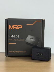
The HM-LD1 is designed for practical integration into robots, UAVs, cameras, security systems, and embedded platforms. It supports indoor or nighttime ranging up to 25 m and outdoor daytime ranging up to 8 m. Its 60° horizontal by 45° vertical field of view creates a useful forward-looking perception cone for obstacle detection, presence monitoring, distance measurement, and local environmental awareness. With UART, UDP, and UVC interfaces, it gives engineering teams flexibility across microcontroller, networked, and camera-like development workflows.
Product page: DTOF Solid state LiDAR HM-LD1
Brochure: Download DTOF SSL HM-LD1 Product Brochure
| Specification | DTOF Solid State LiDAR HM-LD1 |
|---|---|
| Product Name | DTOF Solid state LiDAR HM-LD1 |
| Technology | SPAD dToF solid-state LiDAR |
| Dimensions | 43.5 mm × 30 mm × 26.5 mm |
| Weight | 28 g |
| Indoor Ranging Capability | 0.5–25 m |
| Outdoor Ranging Capability | 0.2–8 m |
| Ranging Accuracy | ±3 cm |
| Field of View | 60° horizontal × 45° vertical |
| Resolution | 40 × 30 |
| Frame Rate | 10 fps |
| Interfaces | UART / UDP / UVC |
| Operating Temperature | -20 ℃ to 60 ℃ |
| Power Consumption | 1.2 W |
| Output Data | Depth image and 3D point cloud data |
| Typical Platforms | PCs, Raspberry Pi, embedded Linux platforms, flight controllers, robot controllers |
| SDK Support | x86 Windows, x86 Linux, ARM Linux |
| Product URL | View HM-LD1 Product Page |
What These Specifications Mean in Practice
The dimensions of 43.5 mm × 30 mm × 26.5 mm support compact mechanical integration into robot panels, UAV frames, smart camera housings, and embedded sensing modules. The 28 g weight makes the HM-LD1 relevant for drones and mobile robots where payload and balance matter. The 0.5–25 m indoor ranging capability supports warehouses, corridors, laboratories, service environments, and nighttime use, while the 0.2–8 m outdoor ranging capability supports close-to-medium outdoor perception.
The listed ±3 cm ranging accuracy is useful for obstacle distance estimation, approach control, docking support, and zone-based presence detection. The 60° × 45° field of view gives robots a practical perception cone, and the 40×30 resolution at 10 fps provides structured depth information for embedded processing. The UART/UDP/UVC interfaces allow engineering teams to evaluate and deploy the module across serial, networked, and camera-like workflows. The 1.2 W power consumption helps battery-powered platforms manage energy budgets.
MRP specializes in perception and positioning modules for robots and UAVs, with a focus on navigation devices and solutions. The company provides professional technical support for product integration and application, direct manufacturing from the source factory for stable supply, and customized products on demand. For B2B teams, this combination of hardware, SDK support, and integration assistance can reduce risk during evaluation and production planning.
Application Scenarios for dToF LiDAR Modules
Autonomous Mobile Robots
AMRs can use dToF LiDAR for aisle navigation, obstacle zones, docking, pallet detection, and human presence detection. In warehouses and factories, local depth data helps identify temporary obstacles that are not present in the map. A forward-facing depth module can also support approach control when the robot moves toward a docking station, rack, cart, or conveyor interface.
Robot Vacuums and Low-Profile Service Robots
Low-profile robots often cannot accommodate tall tower-style scanning LiDAR. Embedded dToF modules can be placed in front or side panels to help detect furniture, walls, pets, table legs, thresholds, and low obstacles. This is especially valuable when the product must operate under furniture or in narrow domestic and commercial spaces.
UAVs and Drones
Drones can use compact dToF LiDAR for altitude hold, terrain following, landing assistance, inspection, and collision avoidance. The combination of low weight and active depth measurement is attractive for platforms where every gram matters. A module such as HM-LD1 can contribute distance data near structures, uneven terrain, or landing zones.
Smart Cameras and Security Systems
Smart cameras and security systems can use dToF LiDAR for user presence detection, zone intrusion monitoring, object recognition assistance, autofocus support, and distance-triggered events. Depth data can reduce false triggers by confirming that an object is inside a defined physical zone rather than simply appearing in a 2D image region.
Industrial Inspection
Industrial inspection applications include bridges, expressways, dams, facilities, and infrastructure where non-contact distance measurement is valuable. A dToF LiDAR module can help inspection platforms measure approach distance, maintain clearance, or capture depth context near hard-to-reach structures. In many inspection tasks, the distance data complements visual, thermal, or multispectral sensing.
Volume Measurement and Object Sizing
Depth maps and point clouds can support rough volume estimation, dimension checking, bin occupancy detection, and material pile observation depending on calibration and software. Engineers should validate accuracy for the target material and geometry, because volume measurement performance depends on sensor position, field of view, object reflectivity, and reconstruction algorithms.
How to Select a dToF LiDAR Module
Range
Start by defining the required measurement range. Indoor robots may need reliable perception across corridors or work cells, while outdoor robots must deal with sunlight and more variable surfaces. Outdoor performance is usually harder because ambient light increases background noise. Always compare the listed indoor and outdoor ranges against your actual use case, not a perfect bench-test scenario.
Field of View
A wider field of view captures more scene context, while a narrower field of view may concentrate sensing over a smaller area. For obstacle avoidance, the field of view should cover the robot’s likely collision envelope. For docking, a narrower or carefully aimed view may be acceptable. For UAV terrain following, the sensor angle and field of view should match the flight behavior.
Resolution
Resolution determines how much spatial detail the module provides. Higher resolution can identify smaller objects and more detailed shapes, but it may require more bandwidth and processing. A 40×30 module provides a structured depth grid that can be effective for distance zones, obstacle regions, presence detection, and embedded algorithms.
Frame Rate
Frame rate affects latency and motion response. A slow robot may function well with 10 fps depth updates, while a fast-moving platform may need higher rates or additional sensors. Engineers should evaluate frame rate together with robot speed, stopping distance, filtering delays, communication latency, and control-loop timing.
Accuracy
Accuracy requirements vary by application. Obstacle avoidance may tolerate centimeter-level error if safety margins are conservative. Docking may require more repeatability. Metrology and precision inspection may require specialized sensors and calibration. For HM-LD1, the listed ranging accuracy is ±3 cm, making it useful for many robotic perception and approach-control tasks.
Interface and Software Support
Interface support can determine whether integration is straightforward or painful. UART, UDP, and UVC cover many embedded, networked, and PC-based workflows. SDK support for x86 Windows, x86 Linux, and ARM Linux helps accelerate prototyping and deployment. If ROS is part of the architecture, confirm driver availability, message format, timestamp handling, and coordinate frame configuration.
Mechanical and Power Constraints
Evaluate size, weight, thermal range, power draw, mounting angle, enclosure window, dust exposure, vibration, and cable routing. A compact 1.2 W module may be attractive for battery-powered platforms, but mechanical design still matters. Poor mounting, dirty windows, internal reflections, or a blocked field of view can reduce performance fast.
Supply and Customization
For industrial customers, stable supply, source factory manufacturing, R&D support, and customization options can be just as important as the specification table. A robotics product may require connector changes, housing adaptations, firmware configuration, integration guidance, or long-term availability. Choosing a supplier with product support and manufacturing control can reduce production risk.
Deployment Best Practices for Robotics Engineers
Mounting Position
Place the dToF LiDAR where it has a clear view of the target area. Avoid occlusions from bumpers, protective covers, frames, landing gear, cables, robot arms, and decorative panels. The sensor should see the zone where decisions are needed, not just the easiest spot on the enclosure.
Optical Window Design
Enclosure windows should be selected carefully. Poor optical materials, dirt, scratches, internal reflections, and incorrect window angles can degrade ranging performance. If the sensor is placed behind a protective cover, test the exact production material, thickness, coating, and geometry. Do not assume that every transparent material will work well.
Calibration
Coordinate alignment is essential when depth data is fused with other sensors. Calibrate the relationship between the LiDAR, robot base frame, camera, IMU, and controller. In ROS-based systems, incorrect transforms can cause obstacle points to appear in the wrong location, leading to poor navigation behavior.
Data Filtering
Good filtering improves reliability. Consider temporal smoothing, invalid point rejection, thresholding, region-of-interest selection, confidence filtering where supported, and application-specific logic. For example, a robot may ignore points above a certain height, focus on a forward safety zone, or require repeated detections before triggering a stop.
Environmental Testing
Test across indoor lighting, outdoor daylight, low-reflectivity surfaces, high-reflectivity surfaces, glass, shiny materials, dust, mist, temperature extremes, and vibration. Maximum range is only one metric. Repeatability, false positives, false negatives, edge-of-FOV behavior, and performance during robot motion are equally important.
Safety and System-Level Redundancy
dToF LiDAR can improve perception, but it should be part of a broader robot safety design. Safety-rated applications may require certified safety sensors, braking architecture, risk analysis, and redundant detection methods. For broader positioning and navigation industry context, visit CHC Navigation.
We’ve recently been testing the HM-LD1 compact dToF LiDAR in a variety of r…
dToF LiDAR FAQ
Is embedded dToF LiDAR the future for robot vacuums and low-profile robots?
Are all ToF sensors LiDAR, and how is dToF LiDAR different from a basic ToF depth sensor?
Can I connect a dToF LiDAR module to Raspberry Pi, Jetson, ROS, or embedded controllers without complex hardware work?
What is the difference between a dToF LiDAR depth map and a point cloud?
How far can dToF LiDAR measure outdoors?
Can dToF LiDAR replace a 2D or 3D spinning LiDAR?
What resolution is enough for robotic obstacle avoidance?
Is dToF LiDAR suitable for SLAM?
What interface should I choose: UART, UDP, or UVC?
What should I test before deploying dToF LiDAR in a robot?
Conclusion: Building Compact Robots with 3D Perception
Here’s the practical takeaway: dToF LiDAR is a strong 3D sensing option for modern robots because it combines active ranging, compact mechanical design, depth map output, point cloud capability, and embedded integration flexibility. For navigation, obstacle avoidance, UAV terrain following, inspection, presence detection, smart camera triggering, and embedded vision development, dToF modules can deliver useful real-time spatial awareness without the mechanical complexity of some traditional LiDAR systems.
The DTOF Solid state LiDAR HM-LD1 shows why this category matters for robotics engineering. Its compact 43.5 mm × 30 mm × 26.5 mm housing, 28 g weight, 40×30 resolution, 10 fps frame rate, UART/UDP/UVC interfaces, and SPAD dToF architecture make it relevant for product teams building compact robots, UAVs, cameras, and intelligent sensing platforms. Engineers should still validate range, reflectivity behavior, sunlight performance, mounting geometry, and software integration in their real deployment environment, but the module provides a solid starting point for compact 3D perception.
To evaluate a compact dToF LiDAR module for your robot, UAV, smart camera, or embedded vision system, view the DTOF Solid state LiDAR HM-LD1 or download the HM-LD1 product brochure.
📚 References & Further Reading
- Industry Standard: LiDAR overview on Wikipedia
- Industry Standard: CHC Navigation
- Related Guide: Structured Light: The Precision 3D Vision
- Related Guide: What Is RTK? The Centimeter-Level GPS Navigation
- Related Guide: Why the Tri-Spectral Gimbal Pod Is a Game Changer
- Product Resource: DTOF Solid state LiDAR HM-LD1






