


Standard GPS can usually tell you which field, road, yard, or worksite your machine is sitting in. RTK tells you where it is actually working. Here’s the deal: for drones, autonomous robots, survey rovers, agricultural machinery, unmanned vehicles, and outdoor inspection platforms, that gap is not academic. A few meters of error can shift a map, damage a crop row, miss an inspection point, or let a robot wander off the route you thought it was following. Normal GNSS errors from satellite orbit, clock drift, atmospheric delay, multipath, receiver noise, and weak satellite geometry can easily stack up into meter-level variation. In the shop, that is not good enough for repeatable industrial automation.
RTK, or Real-Time Kinematic positioning, is a GNSS correction technique that uses a base station or correction network to reduce positioning errors while the machine is operating. Instead of trusting satellite signals by themselves, an RTK rover compares its own observations with correction data and uses carrier-phase measurements to calculate centimeter-level coordinates. This guide walks through what RTK is, how it works, what fixed and float mean, how RTK compares with GPS, GNSS, LiDAR, VSLAM, and other navigation technologies, and how to choose an RTK module for drones, robots, AMRs, surveying, agriculture, and autonomous systems.
Table of Contents
- 👉 What Is RTK?
- 👉 How Does RTK Work?
- 👉 RTK vs GPS vs GNSS
- 👉 RTK Accuracy: Fixed, Float, H, V, and RMS Explained
- 👉 Main Components of an RTK System
- 👉 RTK Correction Data and Protocols
- 👉 RTK Applications in Robots, Drones, and Autonomous Systems
- 👉 RTK, LiDAR, VSLAM, and Sensor Fusion
- 👉 How to Choose an RTK Module
- 👉 RTK Module Product Comparison
- 👉 RTK Integration Checklist for Engineers
- 👉 RTK Limitations and Failure Modes
- 👉 RTK FAQ
What Is RTK?
RTK stands for Real-Time Kinematic positioning. It is a GNSS positioning method that improves location accuracy by using real-time correction data from a base station or correction network. A regular consumer GPS receiver may be good enough to get a truck to the right gate, but it often lands in the several-meter accuracy range. A properly installed RTK GNSS system can deliver centimeter-level positioning when the sky view, antenna setup, corrections, and receiver configuration are right. That is why RTK shows up so often in surveying, UAV mapping, precision agriculture, outdoor robotics, autonomous vehicles, port automation, construction positioning, and marine systems.
RTK is not its own satellite constellation. It works with GNSS constellations such as GPS, BeiDou, Galileo, GLONASS, QZSS, and IRNSS. GPS is one satellite system. GNSS is the broader family of global navigation satellite systems. In industrial purchasing conversations, people still say “RTK GPS” all the time, but “RTK GNSS” is usually the cleaner technical term because modern receivers often use multiple constellations and multiple frequency bands. For a deeper terminology overview, see this related guide to GNSS vs GPS.
RTK Meaning in One Sentence
RTK is a real-time GNSS correction method that enables centimeter-level positioning by comparing rover measurements with correction data from a known reference point or correction service. The moving receiver, called the rover, still listens to satellites directly. The difference is that it also uses correction data that represents local GNSS signal errors, so the final position calculation is much tighter than standalone GNSS.
Why RTK Matters for Autonomous Systems
Autonomous machines need more than a rough location pin. A drone doing photogrammetry needs image positions that line up cleanly. A robot following crop rows needs to repeat the same path without drifting into plants. A survey rover needs coordinates that hold up for engineering work. An unmanned ground vehicle may need to stop at the same loading point every shift. Meter-level positioning is fine for smartphone navigation, but it is not enough for route replay, robotic docking, georeferenced mapping, boundary following, precision spraying, or high-confidence inspection workflows.
RTK Is About Absolute Positioning
RTK provides an absolute position in a global coordinate reference, meaning it tells the system where it is on Earth. That is different from local navigation systems that estimate position relative to a starting point, wall, landmark, camera feature, or previous map. Look, most serious autonomous platforms do not rely on one sensor anyway. They combine RTK with local perception technologies. RTK gives the global reference, while cameras, LiDAR, IMU, wheel odometry, or radar help the machine understand what is nearby and continue operating when satellite visibility gets ugly.
How Does RTK Work?
RTK works by using two receivers, or by using one rover receiver plus a correction service. In a traditional setup, a base station is installed at a known location and the rover receiver is mounted on the moving machine. The base and rover observe many of the same satellite signals. Because the base station already knows where it is, it can estimate the errors affecting the GNSS signals in that area. Correction data is then sent to the rover in real time, and the rover uses that data to refine its own position calculation.
The big GNSS error sources are satellite clock error, satellite orbit error, ionospheric delay, tropospheric delay, multipath reflections, receiver noise, and poor satellite geometry. A standard GNSS receiver cannot fully remove those errors by itself. RTK knocks many of them down by comparing rover observations with correction information from a known reference. When the receiver can maintain a fixed RTK solution, the result is far more precise and repeatable.
Base Station and Rover Relationship
The base station does not drive or control the rover. It simply provides correction data. The rover still calculates its own position, velocity, timing, and solution status. In a local RTK setup, the base may transmit corrections over radio, telemetry, Wi-Fi, 4G, or a wired serial connection. In a network RTK setup, the rover may receive corrections through an internet service, often using NTRIP. The right architecture depends on coverage, baseline distance, communication availability, field workflow, and how much control the operator needs over the correction source.
Carrier-Phase Measurement
Standard code-based GNSS positioning uses information encoded in satellite signals. RTK goes further by using carrier-phase measurements, which measure the phase of the radio signal wave itself. Because carrier wavelengths are much shorter than the code features used in basic GNSS, carrier-phase measurements support much higher precision. The hard part is resolving the integer ambiguity. In plain terms, the receiver has to determine the whole number of carrier cycles between satellite and receiver. Once that ambiguity is resolved, the receiver can enter an RTK fixed state.
Real-Time Corrections
RTK needs low-latency correction data. If correction data is delayed, interrupted, mismatched, or pushed through a serial link that cannot keep up, positioning quality can fall apart. The rover may drop from fixed to float, or even back to standalone GNSS. That means correction delivery is a system design issue, not just a receiver feature. Engineers need to think about radio range, cellular availability, RTCM bandwidth, serial port configuration, network latency, and how the host controller reacts when corrections disappear.
Why Multi-Band GNSS Improves RTK
Multi-band GNSS receivers use more than one satellite frequency, such as L1, L2, or L5 depending on constellation and receiver design. Multiple frequencies help the receiver estimate and reduce atmospheric effects, improve ambiguity resolution, and hold a stronger solution in dynamic outdoor environments. Multi-constellation support also increases the number of usable satellites. For drones, rovers, unmanned vehicles, and robots working around trees, industrial equipment, buildings, or uneven terrain, more satellites and more usable frequency data can make fixed-solution availability much better.
RTK vs GPS vs GNSS
GPS, GNSS, and RTK are related, but they are not interchangeable. GPS is the United States satellite navigation constellation. GNSS is the global category that includes GPS, BeiDou, Galileo, GLONASS, QZSS, IRNSS, and other regional or global navigation systems. RTK is a correction technique used with GNSS receivers to improve accuracy. A receiver may be GPS-only, multi-constellation GNSS, RTK-capable, or non-RTK.
For industrial buyers, this distinction matters. A product described as “GPS” may not support multi-constellation reception, multi-band operation, or RTK correction processing. A modern RTK GNSS module should be evaluated based on supported constellations, frequency bands, correction protocols, output messages, interface compatibility, antenna design, environmental protection, and integration support. For a deeper terminology comparison, see our guides to GNSS vs GPS and RTK receptor vs receiver.
| Technology | What It Means | Typical Accuracy | Best Use Case |
|---|---|---|---|
| GPS | U.S. satellite navigation constellation | Meter-level for common receivers | General navigation and location tracking |
| GNSS | Global category including GPS, BeiDou, Galileo, GLONASS, QZSS, and IRNSS | Meter-level to sub-meter depending on receiver and corrections | Multi-constellation positioning and industrial navigation |
| RTK GNSS | GNSS positioning with real-time correction data and carrier-phase processing | Centimeter-level under suitable conditions | Surveying, UAV mapping, robotics, precision agriculture, and autonomous systems |
RTK Accuracy: Fixed, Float, H, V, and RMS Explained
RTK accuracy is not one magic number that shows up everywhere. It depends on satellite visibility, multi-band support, baseline distance from the base station, correction quality, antenna design, multipath environment, receiver firmware, integration quality, and platform dynamics. A receiver mounted on a vibrating UAV, near motors and carbon frames, or under partial tree cover may behave very differently from the same receiver sitting still under open sky.
What RTK Fixed Means
RTK fixed means the receiver has successfully resolved carrier-phase integer ambiguities. This is the preferred state for centimeter-level positioning. When a system is fixed, the receiver has high confidence in its carrier-phase solution, and horizontal accuracy can often reach centimeter-level performance under favorable conditions. In a commercial robot or drone, fixed status should be monitored continuously. Checking it once at startup and then forgetting about it is asking for trouble.
What RTK Float Means
RTK float means the receiver is still estimating carrier-phase ambiguities. Float can happen during startup, after correction interruption, under poor satellite geometry, in heavy multipath, or while the platform moves through partially blocked areas. Float is not always a total failure; it may still be better than standalone GNSS. But it is not the same as fixed RTK, and control software should treat it differently.
Horizontal vs Vertical Accuracy
Horizontal accuracy is usually better than vertical accuracy because satellite geometry tends to constrain horizontal position more strongly than altitude. In specifications, H usually means horizontal accuracy, while V means vertical accuracy. For example, a module specified at H: 1 cm + 1 ppm and V: 1.5 cm + 1 ppm is telling you that vertical uncertainty is expected to be larger than horizontal uncertainty under defined conditions.
Interpreting 1 cm + 1 ppm
The expression 1 cm + 1 ppm describes how positioning accuracy changes with baseline distance. The 1 cm term is the base component, while 1 ppm means one part per million of the base-to-rover distance. In practical field terms, 1 ppm is about 1 mm per kilometer. If the rover is 10 km from the base station, the ppm component adds about 10 mm of uncertainty. That is why baseline distance, correction source quality, and the local environment all matter when interpreting RTK performance.
Main Components of an RTK System
A complete RTK system is more than a receiver module. It usually includes an RTK-capable GNSS receiver, GNSS antenna, base station or correction network, correction data link, power supply, host controller, mechanical mounting structure, data parsing software, and sometimes extra sensors such as IMU, LiDAR, camera, wheel encoder, radar, or odometry input. Every one of those pieces can affect final performance.
RTK Receiver
The receiver processes satellite signals and correction data. It outputs position, velocity, time, solution status, and related navigation messages. Industrial systems should monitor more than latitude and longitude. Fix type, correction age, satellite count, accuracy estimates, and message timing matter. A system that ignores fix status may keep using degraded data without realizing RTK precision has already been lost.
GNSS Antenna
The antenna is a big deal. Poor antenna placement, insufficient gain, nearby metal, cable losses, or weak ground conditions can prevent stable fixed solutions. Integrated antenna RTK modules reduce cable complexity and antenna mismatch risk because the receiver and antenna are designed as one assembly. That can be especially useful for drones, compact robots, unmanned vehicles, and marine platforms where ruggedness and simple installation matter.
Base Station or RTK Network
A local base station makes sense when the operating area is controlled, remote, or needs predictable correction availability. A CORS or NTRIP network can simplify deployment when coverage and network reliability are strong. Survey teams may prefer a base-rover workflow for project control. Robotics teams may select a correction network to reduce hardware overhead. The best choice depends on accuracy requirements, coverage, communication reliability, field workflow, and how much operational control the team needs.
Communication Link
RTCM correction data has to reach the rover reliably. Common delivery paths include radio, 4G, Wi-Fi, telemetry, serial links, or internet-based NTRIP. The communication link must provide enough bandwidth and low enough latency. If the link fails, the receiver may transition from fixed to float, DGPS, or standalone GNSS. For autonomous systems, software should define exactly how the platform behaves when correction quality changes.
Host System
The host may be a flight controller, robot computer, survey controller, embedded board, or autonomy stack. Integration may involve ROS, Python, C++, serial parsing, coordinate transforms, message filtering, timestamp alignment, and safety logic. The host should understand the antenna phase center, coordinate frame, and timing assumptions, especially when RTK is fused with IMU, odometry, LiDAR, or camera data.
RTK Correction Data and Protocols
RTK systems rely on both correction data and navigation output. The rover commonly receives RTCM correction messages and outputs position data using NMEA 0183, UBX, or another receiver-specific protocol. The physical interface is often UART in embedded robotics and UAV systems. Correct baud rate, voltage level, wiring, grounding, and message configuration are essential for reliable operation.
NMEA Output
NMEA 0183 is a common text-based GNSS output format. Messages such as GGA, RMC, VTG, and GSA can provide latitude, longitude, altitude, time, speed, course, fix quality, satellite information, and related navigation data depending on configuration. NMEA is widely supported by flight controllers, embedded computers, survey controllers, and logging tools, which makes it practical for integration and debugging.
RTCM Input
RTCM carries correction information rather than final rover coordinates. The rover uses RTCM data together with its own satellite observations to compute a high-precision position. If RTCM messages are missing, delayed, or incompatible, fixed RTK performance can degrade quickly. Some modules support rover-side RTCM input only, while others can also output RTCM when used on the base side.
UART Integration
TTL-level UART is a common interface for embedded systems. Integrators need to confirm the voltage level, wiring direction, baud rate, connector design, grounding, and electromagnetic environment. A baud rate of 115200 bps is common for compact GNSS modules, but the message set and update rate must be configured so the serial link is not overloaded. Data loss or truncated messages can create strange integration problems that look like receiver issues but are really communication issues.
Timing Synchronization
Timing matters in autonomous systems because sensor data must be lined up correctly. RTK position, IMU acceleration, camera frames, LiDAR scans, wheel odometry, and control commands may all be timestamped and fused. A timing synchronization accuracy specification such as 20 ns can be valuable in applications where precise timing alignment supports better sensor fusion, mapping, and data logging.
RTK Applications in Robots, Drones, and Autonomous Systems
RTK is valuable anywhere outdoor absolute positioning accuracy matters. Its strongest applications are open-sky or semi-open outdoor environments where machines need reliable global position. It does not replace perception sensors, but it gives many industrial automation workflows their coordinate foundation.
RTK for UAV Mapping and Photogrammetry
Drones use RTK to improve image geotagging, reduce dependence on ground control points, repeat flight paths, support agricultural analysis, and streamline survey workflows. In mapping applications, accurate camera position data improves downstream processing and reduces field labor. For inspection routes, RTK helps UAVs return to consistent positions across repeated missions.
RTK for AMRs and Outdoor Robots
Outdoor autonomous mobile robots can use RTK for boundary following, waypoint navigation, route replay, docking zones, outdoor logistics, security patrols, solar farm inspection, and industrial yard automation. RTK is especially useful when a robot must operate over large outdoor areas where indoor localization methods are not practical.
RTK for Precision Agriculture
Agricultural systems use RTK for row guidance, spraying, seeding, crop monitoring, field mapping, and machinery automation. Centimeter-level positioning can reduce crop damage, improve repeatability, and support controlled traffic farming. RTK also helps drones and ground vehicles generate accurate field data for analysis and treatment planning.
RTK for Unmanned Ground Vehicles
Unmanned ground vehicles in mining, construction, ports, industrial campuses, and logistics yards can use RTK for global route reference. It helps vehicles navigate between mapped zones, return to repeatable positions, and georeference operational data. For safety and robustness, RTK is usually combined with obstacle detection and local perception.
RTK for Marine and Industrial Positioning
Marine platforms, unmanned surface vessels, buoys, ships, dock inspection systems, and harsh industrial environments can benefit from rugged RTK modules. Waterproofing, temperature range, antenna integration, and mechanical durability matter in these applications because environmental exposure directly affects reliability and service life.
RTK, LiDAR, VSLAM, and Sensor Fusion
RTK provides outdoor absolute positioning, but it does not detect obstacles, classify objects, map indoor environments, or solve every localization problem near buildings, under bridges, in tunnels, or under dense tree canopy. Autonomous platforms often combine RTK with perception sensors such as LiDAR from companies like Ouster and imaging components from semiconductor suppliers such as onsemi.
RTK gives the global coordinate reference. LiDAR provides local 3D perception and mapping. VSLAM uses camera data to estimate motion and build local maps. IMU provides high-rate motion estimation. Wheel odometry estimates relative movement. Radar can provide robust detection in dust, fog, rain, or poor visibility. For robotics teams comparing perception stacks, our guide to LiDAR vs Radar for Robotics explains how local sensing complements global positioning.
When RTK Is Enough
RTK may be enough for open-sky waypoint navigation, survey mapping, field machinery, and applications where the environment is predictable and obstacle avoidance is handled separately. A simple rover operating in a clear field may only need RTK plus basic safety sensing. A survey pole or mapping drone may rely heavily on RTK because the main job is accurate coordinate capture rather than complex obstacle interaction.
When RTK Is Not Enough
RTK is not enough when a system must avoid people, vehicles, equipment, walls, trees, pallets, cables, or dynamic obstacles. It also degrades indoors, near tall buildings, around reflective structures, under bridges, in forests, and inside tunnels. If an autonomous vehicle uses RTK alone, it may know its approximate global position but still have no real understanding of what is immediately around it.
Why Sensor Fusion Is Often Best
Robust autonomy often uses RTK for global position, LiDAR or cameras for perception, IMU for high-rate motion estimation, and software fusion to combine data streams. Sensor fusion helps bridge short GNSS outages, smooth dynamic motion, detect nearby objects, and maintain localization in mixed environments. In practical field deployments, RTK should be treated as one part of the navigation stack, not the whole machine brain.
How to Choose an RTK Module
Choosing an RTK module starts with the application. A lightweight UAV may prioritize compact dimensions, low integration complexity, and stable antenna performance. A survey rover may prioritize base/rover flexibility, antenna performance, and field communication options. A marine or industrial robot may prioritize waterproofing, operating temperature, and mechanical durability. The best module is not simply the one with the strongest headline accuracy. It is the one that fits the platform, environment, and workflow.
Frequency Band Support
Supported constellations and frequency bands strongly affect real-world availability. GPS, BeiDou, Galileo, GLONASS, QZSS, and IRNSS support can increase satellite visibility. L1, L2, and L5 class frequency support can improve atmospheric error handling and ambiguity resolution depending on receiver design. Multi-band support is especially useful in UAVs, rovers, and autonomous systems that must operate in changing outdoor environments.
Integrated Antenna vs Separate Antenna
Integrated antenna modules simplify installation and reduce antenna cable issues. They can also reduce mismatch risk because the receiver and antenna are designed together. Separate antenna systems may offer more flexible placement, but they require careful cable selection, connector reliability, mounting position, and ground plane design. In compact robots and drones, integrated modules can reduce mechanical and electrical complexity.
Interface and Protocol Compatibility
Confirm that the module supports the protocol your host system expects. Common requirements include NMEA 0183 output, RTCM correction input, TTL-level UART, and a compatible baud rate. Some workflows may also need base-side RTCM output. Integration teams should verify update rate, message set, voltage levels, connector layout, and software parsing before finalizing a module.
Ruggedness and Environmental Protection
Outdoor RTK hardware may face rain, dust, vibration, heat, freezing temperatures, UV exposure, and mechanical shock. Important specifications include IP rating, operating temperature, housing design, waterproofing, UV resistance, and mounting stability. For marine, agriculture, robotics, and industrial positioning systems, environmental durability can be just as important as positioning accuracy.
Size and Weight
Drones and compact mobile robots often prioritize low weight and small dimensions. Larger survey systems may accept a bigger antenna module for signal performance and field usability. A small integrated helical antenna module can be attractive for space-constrained installations, while a larger mushroom-shaped survey module can be suitable for professional mapping, base/rover workflows, and outdoor field systems.
Need help selecting an RTK module for a drone, robot, rover, or autonomous platform? Compare HM-D20 and HM-D13 below or contact our engineering team for integration support with UART, RTCM corrections, antenna placement, and field validation.
RTK Module Product Comparison
When selecting an RTK receiver module, the best option depends on whether the priority is compact integration, antenna performance, rugged outdoor deployment, or base/rover flexibility. The following modules are designed for robotics, UAVs, unmanned vehicles, surveying, mapping, and outdoor autonomous positioning applications.
Helical Antenna RTK Module HM-D20
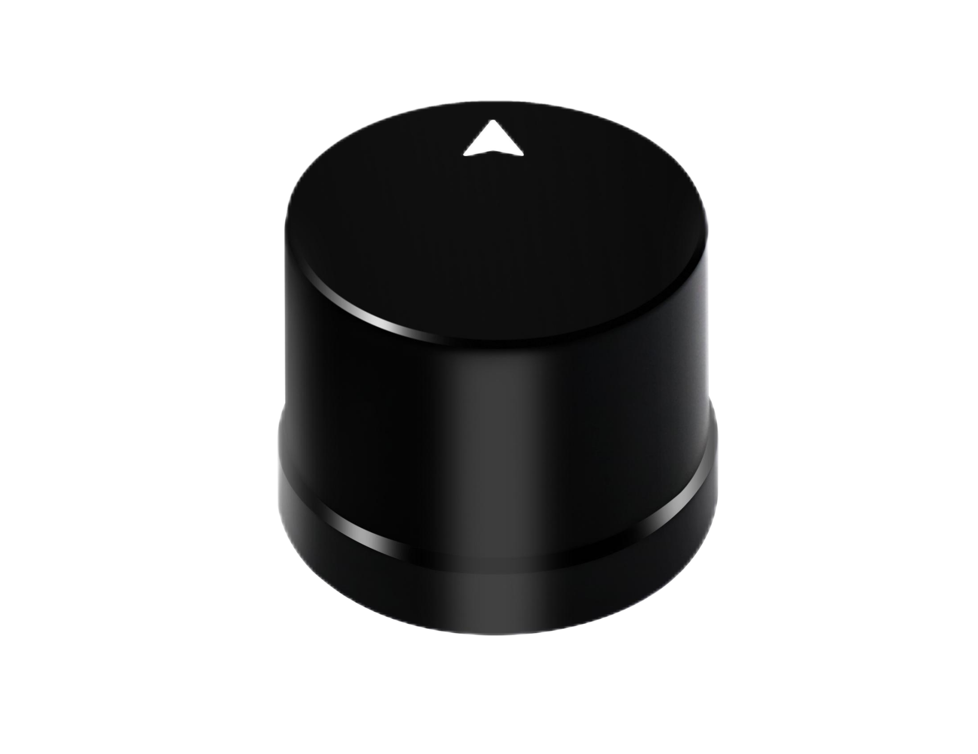
The Helical Antenna RTK Module HM-D20 is a compact integrated RTK module designed for UAVs, unmanned vehicles, ships, robots, and outdoor positioning systems. It combines a built-in GNSS module and antenna, so users can deploy it without an external antenna. This integrated design helps reduce cabling complexity and supports fast installation in space-constrained platforms.
The HM-D20 supports GPS L1/L5, BeiDou B1/B2A/B2I, GLONASS G1, Galileo E1/E5, QZSS L1/L5, and IRNSS L5. Its RTK position accuracy is specified as H: 1 cm + 1 ppm and V: 1.5 cm + 1 ppm. It provides NMEA 0183 output and RTCM input at the rover side, uses a TTL-level UART interface, and operates at 115200 bps. The module has 20 ns timing synchronization accuracy, compact Φ44 × 37 mm dimensions, an operating temperature range from -40 ℃ to 85 ℃, and IP67 waterproof protection.
Choose HM-D20 when compact dimensions, integrated antenna design, waterproof performance, and easy UART integration are priorities. It is especially suitable for drones, compact robots, unmanned vehicles, ships, and outdoor positioning systems where an external antenna would add wiring complexity.
Multiband RTK Survey Module HM-D13
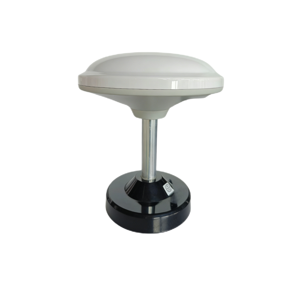
The Multiband RTK Survey Module HM-D13 is an integrated mushroom-shaped multiband RTK survey module for professional surveying, UAV navigation, mapping, and embedded positioning systems. It is designed for multi-system positioning and stable signal reception, combining module and antenna in an all-in-one structure for outdoor field use.
The HM-D13 supports GPS L1/L5, BeiDou B1/B2A/B2I, Galileo E1/E5, QZSS L1/L5, GLONASS G1, and IRNSS. Its RTK position accuracy is specified as H: 1 cm + 1 ppm and V: 1.5 cm + 1 ppm. It supports NMEA 0183 output and RTCM input at the rover side, plus RTCM output at the base side. It uses a TTL-level UART interface, operates at 115200 bps, provides 20 ns timing synchronization accuracy, measures Φ152 × 67.9 mm, weighs less than 550 g, and operates from -40 ℃ to 85 ℃. It also supports an optional 4G radio module.
Choose HM-D13 when the application needs a larger integrated survey-style antenna module, base-side RTCM output support, optional 4G radio module capability, and professional survey or mapping workflows. It is suitable for survey rovers, UAV navigation, field mapping, and systems that benefit from base/rover flexibility.
| Specification | Helical Antenna RTK Module HM-D20 | Multiband RTK Survey Module HM-D13 |
|---|---|---|
| Product URL | HM-D20 product page | HM-D13 product page |
| Frequency band | GPS L1/L5, BeiDou B1/B2A/B2I, GLONASS G1, Galileo E1/E5, QZSS L1/L5, IRNSS L5 | GPS L1/L5, BeiDou B1/B2A/B2I, Galileo E1/E5, QZSS L1/L5, GLONASS G1, IRNSS |
| RTK position accuracy | H: 1 cm + 1 ppm, V: 1.5 cm + 1 ppm | H: 1 cm + 1 ppm, V: 1.5 cm + 1 ppm |
| Protocol | NMEA 0183 output and RTCM input at rover side | NMEA 0183 output and RTCM input at rover side. RTCM output at base side. |
| Baud rate | 115200 bps | 115200 bps |
| Dimensions | Φ44 × 37 mm | Φ152 × 67.9 mm |
| Interface | TTL level UART interface | TTL level UART interface |
| Timing synchronization accuracy | 20 ns | 20 ns |
| Operating temperature | -40 ℃ to 85 ℃ | -40 ℃ to 85 ℃ |
| Waterproof / protection | IP67 | High outdoor protection level; windproof and rainproof design |
| Weight | Not specified | <550 g |
| Additional notes | Built-in GNSS module and antenna; no external antenna required | Supports optional 4G radio module |
| Recommended fit | Compact UAVs, robots, unmanned vehicles, ships, and space-constrained outdoor systems | Surveying, mapping, UAV navigation, base/rover workflows, and professional outdoor positioning systems |
Explore RTK modules for compact UAV integration, survey workflows, unmanned vehicles, and outdoor autonomous positioning. HM-D20 is optimized for compact rugged integration, while HM-D13 supports larger survey-style workflows with base/rover flexibility.
RTK Integration Checklist for Engineers
RTK integration should be treated as a full engineering system task. A strong receiver cannot overcome poor antenna placement, wrong serial settings, unstable power, weak correction delivery, or software that ignores solution status. In the shop and in the field, most “bad RTK” complaints trace back to integration details. Use the following checklist before deployment.
- ⚙️ Confirm the receiver supports required GNSS constellations and frequency bands.
- ⚙️ Confirm whether the module will operate as rover only or as both base and rover.
- ⚙️ Match correction data format, usually RTCM.
- ⚙️ Match output format, such as NMEA 0183.
- ⚙️ Configure UART voltage level, wiring, baud rate, and message rate.
- ⚙️ Mount the antenna with clear sky visibility.
- ⚙️ Avoid metal obstructions and reflective surfaces near the antenna.
- ⚙️ Verify coordinate frame and antenna phase center assumptions.
- ⚙️ Log fixed and float status during field testing.
- ⚙️ Check horizontal and vertical accuracy separately.
- ⚙️ Confirm latency requirements for the host system.
- ⚙️ Test under realistic operating conditions, not only open-sky static conditions.
- ⚙️ Validate behavior during correction loss.
- ⚙️ Integrate RTK data with IMU, odometry, LiDAR, or VSLAM if autonomy requires robust navigation.
Mechanical Mounting
Mount the antenna where it has the clearest possible sky view. Avoid placing it near motors, metal frames, high-current wiring, batteries, tall structures, or reflective surfaces. For drones and vehicles, consider vibration and tilt. For survey systems, maintain a consistent antenna phase center reference. For marine and industrial platforms, check waterproofing, cable strain, and housing exposure.
Electrical Integration
Confirm TTL UART voltage level, connector pinout, power stability, baud rate, grounding, and electromagnetic interference. Many integration issues come from basic electrical mismatches rather than receiver performance. If the host controller cannot reliably receive the configured data stream, the navigation stack may use delayed or incomplete data.
Software Parsing
Software should parse position data, fix status, correction age, timestamp, coordinate frame, and quality indicators. It should also handle transitions between fixed, float, and standalone GNSS. For robot and UAV systems, RTK data may need coordinate conversion before use in the control stack. Engineers should log raw messages during testing so integration problems can be diagnosed later.
Field Validation
Begin with open-sky static tests to confirm fixed status. Then run dynamic tests on the actual machine, including acceleration, turning, vibration, route repeatability, and correction dropout. Test near buildings, trees, vehicles, docks, fields, or worksite structures that represent real deployment conditions. Datasheet accuracy is useful, but field behavior is what tells you whether the system is ready for commercial operation.
RTK Limitations and Failure Modes
RTK is powerful, but it is not magic. Accuracy can degrade when satellites are blocked, multipath reflections occur, the antenna is poorly mounted, correction data is unavailable, baseline distance is too long, the receiver cannot maintain fixed solution, the platform experiences vibration or tilt, or the host system misinterprets coordinate frames and timestamps. Reliable deployment requires realistic expectations and real field validation.
Multipath
Multipath occurs when satellite signals reflect from buildings, vehicles, water, metal structures, or other surfaces before reaching the antenna. The receiver may interpret these reflected signals as distorted observations, reducing accuracy or preventing fixed ambiguity resolution. Antenna placement and environment awareness are two of the best defenses against multipath.
Correction Dropout
If RTCM correction data stops arriving, the receiver may transition from fixed to float, DGPS, or standalone GNSS. The host system should detect this change and respond appropriately. For an autonomous machine, that might mean slowing down, stopping, switching to sensor-fusion fallback, or reducing reliance on global position until corrections return.
Urban Canyon and Tree Canopy
Tall buildings and dense foliage reduce satellite visibility and create reflected signals. RTK can still work in some partially obstructed environments, but fixed-solution reliability may decrease. This is why field testing should include the actual operating environment, not only ideal open-sky conditions.
Dynamic Motion and Vibration
UAVs, ground vehicles, robots, and marine platforms introduce dynamic effects such as vibration, tilt, acceleration, and changing antenna orientation. Good mechanical mounting, filtering, and sensor fusion can improve system behavior. If RTK data is used for control, engineers should verify update rate, latency, and data quality during real motion.
Why Real-World Testing Matters
RTK specifications are usually measured under defined conditions. Real deployment may include tree cover, reflective structures, rain, vibration, electrical noise, correction delays, and software integration constraints. Before using RTK in mission-critical systems, teams should test fixed-solution stability, dropout behavior, repeatability, and recovery under realistic conditions.
a short-flex design and a long-flex design for different robotics and UAV d…
RTK FAQ
What is RTK and how does it improve normal GPS accuracy?
What do RTK fixed, float, H, V, and RMS mean during a survey or robot navigation test?
Should I choose RTK, VSLAM, LiDAR, or combine them for robot navigation?
Is RTK the same as GPS?
Does RTK require a base station?
What is the difference between RTK and PPK?
What accuracy can RTK achieve in real conditions?
What does 1 cm + 1 ppm mean in an RTK accuracy specification?
What protocols are used in RTK systems?
Can RTK be used indoors?
Why does RTK sometimes lose fixed status?
What is the best RTK module for drones?
What is the best RTK module for robots and autonomous vehicles?
Does an integrated RTK antenna module perform better than a separate antenna system?
What should I test before deploying RTK in a commercial system?
Discuss your RTK application with our technical team and get support for module selection, UART integration, RTCM correction setup, and robot or UAV positioning workflows.
📚 References & Further Reading
- Industry Standard: Ouster LiDAR and perception technology
- Industry Standard: onsemi imaging and sensing components
- Related Guide: GNSS vs GPS
- Related Guide: RTK receptor vs receiver
- Related Guide: LiDAR vs Radar for Robotics
- Product Resource: Helical Antenna RTK Module HM-D20
- Product Resource: Multiband RTK Survey Module HM-D13






