

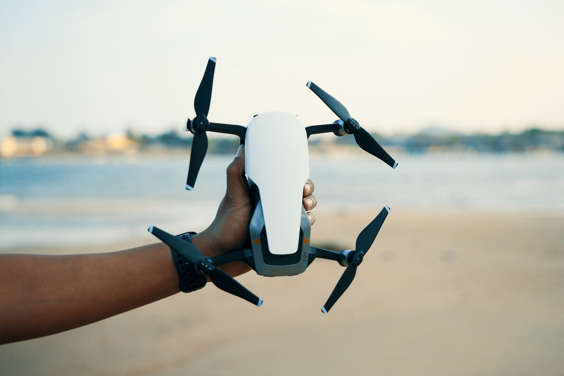
Drone RTK Guide: Build Centimeter-Accurate UAV Mapping Systems Without Costly Integration Mistakes
Drone RTK is not some fancy add-on reserved for giant survey fleets anymore. It has become a practical positioning backbone for UAV mapping, inspection, precision agriculture, robotics, unmanned vehicles, marine platforms, and autonomous navigation systems where ordinary GPS just does not cut it. Here’s the deal: the hard part is not buying an RTK module. The hard part is building a complete centimeter-accurate UAV positioning system where the GNSS receiver, antenna, correction source, flight controller, UART interface, NMEA data stream, RTCM input, timing synchronization, mechanical layout, and software stack all behave like one reliable field system.
This guide looks at drone RTK from an integration-first point of view. It is written for engineers, UAV builders, survey teams, robotics developers, system integrators, and industrial buyers who care about usable accuracy, not brochure accuracy. You will learn how drone RTK works, why multiband GNSS matters, how correction workflows should be evaluated, where unstable fixes come from, and how to compare real modules such as the Multiband RTK Survey Module HM-D13 and the Helical Antenna RTK Module HM-D20 for professional UAV and robotics projects.
Look, centimeter accuracy sounds simple until you try to make it repeatable on a flying machine. A drone is a noisy, vibrating, power-hungry platform with radios, carbon fiber, spinning motors, payload wiring, and changing sky view. RTK can absolutely deliver serious accuracy, but only when the whole installation is designed like an engineered system instead of a loose collection of parts.
In the shop, most RTK problems show up before the aircraft ever leaves the ground. Bad UART wiring, mismatched voltage levels, weak correction links, poor antenna placement, undocumented coordinate frames, and sloppy logging can ruin an otherwise good receiver. The goal of this guide is to help you avoid those expensive mistakes before they turn into bad maps, failed inspections, or unreliable autonomous behavior.
Table of Contents
- 👉 What Is Drone RTK?
- 👉 Why Centimeter Accuracy Matters in UAV Mapping
- 👉 How Drone RTK Works
- 👉 Drone RTK System Architecture
- 👉 RTK vs PPK vs Standard GPS
- 👉 RTK Correction Data Workflows
- 👉 How to Choose a Drone RTK Module
- 👉 Costly Drone RTK Integration Mistakes
- 👉 Recommended RTK Modules and Real Specifications
- 👉 Drone RTK Implementation Checklist
- 👉 Industrial Applications of Drone RTK
- 👉 Drone RTK FAQ
What Is Drone RTK?
Drone RTK means using Real-Time Kinematic GNSS positioning on a UAV to get far better positioning precision than standard GPS or conventional GNSS. In a typical drone RTK setup, the aircraft carries an RTK rover module that receives satellite signals and correction data. When the correction workflow, antenna placement, sky view, and software configuration are right, the system can reach centimeter-level positioning under suitable open-sky conditions.
Standard GNSS positioning usually relies on code-based satellite measurements and often lands in the meter-level accuracy range. That may be fine for hobby navigation, rough flight logging, or approximate geotagging. It is not enough for professional mapping, asset inspection, precision agriculture, repeatable autonomous routes, or engineering workflows where the data needs to line up mission after mission. RTK improves accuracy by using carrier-phase measurements, which are much more precise than basic code measurements but require correction data and ambiguity resolution.
A complete RTK drone system normally includes GNSS satellites, a UAV-mounted RTK rover module, a GNSS antenna, a correction data source, a flight controller or onboard computer, supported data protocols, stable serial communication, and sensible mechanical placement. In embedded UAV systems, NMEA output and RTCM input matter a lot because the rover must output useful navigation data while also receiving correction data from a base station, NTRIP network, radio link, or another correction source.
Drone RTK does not make a UAV accurate by magic. It reduces positioning error by comparing satellite signal observations between a rover and a reference correction source. In practical field workflows, the rover is mounted on the aircraft, while correction data may come from a local base station, an internet-based NTRIP service, or a radio-connected correction network. The final result depends on how well the full system is integrated, tested, monitored, and validated.
For engineering teams combining GNSS positioning with machine vision and perception modules, it helps to understand how different measurement systems behave at the principle level. A related educational resource is this guide on what phase means in 3D structured light cameras, which can help teams think more clearly about measurement, calibration, and sensor integration.
Why Centimeter Accuracy Matters in UAV Mapping
Centimeter accuracy matters because UAV mapping is not just about flying a drone and collecting pretty images. It is about producing spatial data that engineers, surveyors, inspectors, farm managers, and operations teams can trust. A few meters of positioning error can cause misaligned orthomosaics, poor repeatability between flights, inaccurate asset locations, unreliable inspection overlays, and extra ground control point labor.
Mapping Accuracy Is a System-Level Outcome
One of the most common drone RTK buying mistakes is assuming that receiver accuracy automatically equals final map accuracy. It does not. Mapping accuracy is a system-level outcome. It depends on RTK fixed status, camera trigger synchronization, GNSS antenna phase center, camera calibration, lens distortion, flight altitude, ground sampling distance, image overlap, photogrammetry software, coordinate system settings, and control point strategy. A good RTK module is essential, but it is still only one part of the chain.
For example, if the RTK antenna phase center is not properly related to the camera center, the geotagged image position may still be offset. If the camera trigger timing is sloppy, the recorded position may not match the actual exposure moment. If the drone flies near reflective structures or under partial sky blockage, multipath and satellite geometry can reduce fix stability. That is why serious drone RTK work requires both hardware selection and workflow validation.
Where Standard GPS Fails
Standard GPS or basic GNSS can work well for approximate navigation, but it usually falls short when a team needs survey-grade repeatability. Meter-level horizontal errors may not look terrible during ordinary flight, but they become a real problem when comparing construction progress over time, measuring agricultural row alignment, documenting mining stockpiles, or returning to the exact same inspection location. The problem gets worse when mapping data must be integrated into GIS, CAD, BIM, machine control, or asset management platforms.
Without RTK or another high-precision positioning workflow, teams often lean heavily on ground control points. Ground control can improve final mapping accuracy, but it adds field labor, requires survey setup, and slows repeated operations. Drone RTK helps reduce that burden by improving direct georeferencing and making repeat flights more consistent.
Where RTK Adds Value
RTK adds value in precision agriculture, construction monitoring, road and railway corridor mapping, solar farm inspection, powerline inspection, mining stockpile measurement, robotics localization, autonomous landing, docking operations, and payload navigation. The value is not just raw accuracy. The real payoff comes from repeatability, cleaner datasets, less manual correction, better asset localization, and more reliable automation.
From an industrial purchasing standpoint, drone RTK should be viewed as a cost-control technology. It can reduce downstream correction labor, improve confidence in deliverables, reduce rework, and support repeatable field operations. The return on investment often comes from faster processing, fewer manual checkpoints, better consistency between missions, and better decisions.
How Drone RTK Works
Drone RTK works by combining satellite observations from the UAV-mounted rover receiver with correction data from a reference source. GNSS satellites transmit signals received by both the rover and the base or correction network. Because the reference source has a known or tightly controlled position, it can help correct errors that affect satellite measurements. These errors may include atmospheric delay, satellite clock error, orbit error, and other measurement biases.
Satellite Signals and Carrier Phase
Standard GNSS receivers often use code-based measurements, which are useful but relatively coarse. RTK uses carrier-phase observations, which allow much finer measurement of the satellite signal. Carrier-phase measurement is powerful because the phase of the signal can be measured very precisely. The catch is that the receiver must resolve ambiguity in the number of full carrier cycles between the satellite and receiver. That is why RTK requires correction data and why the system may report states such as single, float, and fixed.
When discussing broader sensing and imaging systems across industrial applications, readers can explore research and education resources from SPIE. Optical sensing and GNSS positioning are different technical domains, but both demand attention to signal quality, calibration, environmental conditions, and system-level engineering.
Rover, Base, and Corrections
The rover is the RTK receiver mounted on the drone. It receives GNSS satellite signals and correction data, then calculates a corrected position. The base station is a receiver located at a known coordinate or a coordinate established through a suitable surveying procedure. The base generates correction data that is transmitted to the rover, often in RTCM format. The rover then outputs navigation information to the flight controller or onboard computer, commonly using NMEA 0183 output in embedded systems.
In many UAV architectures, the flight controller uses the RTK position for navigation, while an onboard computer may use the same position for logging, geotagging, sensor fusion, or mapping. That makes protocol compatibility important. A module may have strong RTK performance, but if the data output format, UART voltage level, baud rate, or correction input format is not supported by the rest of the platform, the integration can fail before the aircraft ever flies.
RTK Float vs RTK Fixed
RTK float means the receiver is using correction data, but the carrier-phase ambiguity has not been fully resolved. Accuracy may be better than standalone GNSS, but it is not the most reliable centimeter-level state. RTK fixed means the ambiguity has been resolved, and centimeter-level performance becomes possible under suitable conditions. Single GNSS means the receiver is not using a corrected RTK solution and may operate closer to ordinary GNSS accuracy.
For professional drone RTK systems, monitoring the RTK state is not optional. A flight may begin with RTK fixed status and later lose correction data during the mission. If the system does not log fix type, correction age, satellite count, and other quality indicators, the operator may not discover the problem until processing the data later.
Why Multiband GNSS Matters
Multiband GNSS modules receive multiple satellite frequencies such as GPS L1 and L5, BeiDou B1, B2A, and B2I, Galileo E1 and E5, QZSS L1 and L5, GLONASS G1, and IRNSS L5 depending on receiver design. Multiple bands improve robustness because they help the receiver handle ionospheric delay, increase satellite availability, and strengthen positioning reliability in real field conditions. For drone RTK mapping, multiband reception can improve time-to-fix, correction stability, and operational confidence.
Drone RTK System Architecture
A drone RTK system should be designed as a full positioning architecture, not a single receiver installation. The aircraft receives GNSS signals through the onboard antenna and RTK module. The rover receives correction data from a base station, NTRIP network, RTCM radio, or other correction source. The rover then outputs navigation data to the flight controller, onboard computer, mapping payload, camera trigger system, or data logger.
Hardware Components
The first hardware component is the RTK rover module. This is the receiver installed on the UAV or robotic platform. It processes GNSS signals, receives correction data, and generates corrected navigation output. The second component is the GNSS antenna. Some systems use external antennas, while integrated RTK modules combine the receiver and antenna into one physical package. Integrated designs can reduce cable routing, impedance matching, connector problems, antenna selection errors, and first-time installation risk.
The third component is the flight controller or onboard computer. It receives the RTK position output and uses it for navigation, logging, geotagging, autonomy, or sensor fusion. The fourth component is the correction source, which may be a local base station, an NTRIP correction network, a radio correction link, or a 4G-supported correction workflow. The fifth component is the communication interface. UART is common in embedded UAV systems, and both voltage level and baud rate must be verified before integration.
Software Components
The software side of drone RTK includes NMEA parsing, RTCM ingestion, RTK status monitoring, coordinate frame handling, timestamp management, flight controller configuration, and data logging. Robotics teams may also need ROS integration, Python parsing tools, C++ drivers, or custom middleware. Survey teams may need reliable geotagging workflows, camera event logging, and photogrammetry compatibility.
UAV teams building custom embedded control or edge-computing systems may also evaluate development hardware such as the RISC-V Dev Board HM-RV1. In many industrial projects, precise GNSS positioning is only one part of a broader embedded system that includes cameras, LiDAR, inertial measurement, telemetry, storage, and mission logic.
Timing Synchronization
Timing synchronization matters because position data must be aligned with real events such as image exposure, LiDAR scans, payload measurements, or navigation decisions. A timing synchronization accuracy specification such as 20 ns, as provided in the HM-D13 and HM-D20 data, can be valuable when coordinating GNSS position data with camera triggering, sensor fusion, or high-precision logging. Even when the final application is not a formal survey workflow, strong timing discipline improves confidence in multi-sensor datasets.
RTK vs PPK vs Standard GPS
Drone positioning workflows are often compared using three categories: standard GPS or GNSS, RTK, and PPK. Each one has a different job. Choosing the right method depends on whether the project needs real-time navigation accuracy, post-processed mapping accuracy, simple flight logging, or a combination of those requirements.
Standard GPS
Standard GPS or ordinary GNSS is the easiest positioning method to deploy. It does not require a correction link, base station, NTRIP account, or RTCM input. It is suitable for basic navigation, hobby use, and general flight logs. The downside is obvious: it is usually not survey-grade. Meter-level error can be unacceptable when a team needs accurate maps, repeatable inspection routes, precise asset locations, or consistent measurements over time.
RTK
RTK is a real-time correction workflow. It can provide centimeter-level positioning under proper conditions while the drone is flying. This makes RTK valuable for live geotagging, precision landing, autonomous navigation, mapping, inspection, and robotics. The main limitation is that the system requires stable correction data during operation. If the correction link fails, the receiver may degrade from fixed to float or standalone GNSS.
PPK
PPK, or post-processed kinematic positioning, applies correction after the flight. It is often used in high-end surveying and mapping where real-time precision navigation is less important than final processed accuracy. PPK can be more tolerant of correction-link interruptions because correction does not need to be maintained live during the mission. However, it does not provide the same real-time precision for navigation, live inspection, or autonomous control.
| Positioning Method | Correction Timing | Typical Accuracy | Best For | Main Limitation |
|---|---|---|---|---|
| Standard GPS / GNSS | None | Meter-level | Basic navigation and consumer flight logs | Not survey-grade |
| RTK | Real time | Centimeter-level under proper conditions | Mapping, autonomy, inspection, and precision landing | Requires stable correction data |
| PPK | Post-processing | Centimeter-level after processing | Surveying and photogrammetry deliverables | Does not provide real-time precision navigation |
RTK Correction Data Workflows
RTK correction data is the difference between a high-accuracy positioning system and a receiver that only behaves like ordinary GNSS. A drone RTK rover must receive compatible correction information to calculate a fixed RTK solution. The best correction workflow depends on operating environment, network coverage, flight area, required repeatability, and project budget.
Local Base Station Workflow
A local base station workflow places a GNSS receiver at a known point or a point established through an appropriate field procedure. The base station observes satellite signals and sends correction data to the rover on the drone. This approach is common in construction, mining, agriculture, remote surveying, and areas where cellular correction networks are unavailable or unreliable. It gives the project team direct control over the correction source, but it requires base setup, coordinate management, and a reliable communication link to the UAV.
NTRIP Network Workflow
NTRIP delivers correction data over the internet. This can simplify deployment in regions with established correction networks and reliable cellular service. A drone, ground station, or connected device receives the correction stream and passes it to the rover. NTRIP can be convenient for recurring operations in developed areas, but it depends on network availability, subscription access, and stable data connectivity during flight.
Radio and 4G Correction Links
Radio correction links are useful when teams need independence from public cellular networks. They can support remote sites, temporary worksites, and local base-rover workflows. A 4G-supported correction option can also simplify industrial deployment when cellular coverage is available. The HM-D13 specifically supports an optional 4G radio module, which matters for teams designing base-rover workflows or field systems that need flexible correction delivery.
RTCM Compatibility
RTCM is a common correction format in RTK systems. The rover must accept RTCM correction input, and the base or correction source must provide compatible RTCM data. The HM-D13 supports NMEA 0183 output and RTCM input at the rover side, plus RTCM output at the base side. The HM-D20 supports NMEA 0183 output and RTCM input at the rover side. These protocol details matter because many failed drone RTK integrations happen when buyers confirm that a product is “RTK supported” but do not verify correction format, base-station compatibility, UART level, baud rate, and flight controller support.
How to Choose a Drone RTK Module
Choosing a drone RTK module should start with the application, not the catalog page. A mapping UAV, compact FPV platform, autonomous boat, ground robot, and industrial inspection drone may all need RTK, but they do not have identical mechanical, environmental, communication, and integration requirements.
Frequency Band Support
Prioritize multiband GNSS support when the application requires professional accuracy and field reliability. Strong constellation and frequency coverage can include GPS L1 and L5, BeiDou B1, B2A, and B2I, Galileo E1 and E5, QZSS L1 and L5, GLONASS G1, and IRNSS L5 depending on the module. More constellations and bands increase satellite availability and can improve performance in environments where sky view, multipath, or geometry is not ideal.
RTK Accuracy Specification
RTK accuracy specifications such as H: 1 cm + 1 ppm and V: 1.5 cm + 1 ppm must be read carefully. The centimeter term describes baseline performance under suitable conditions, while ppm indicates that error grows with baseline distance. One ppm is approximately one millimeter per kilometer. This matters when the drone operates far from the base station. Buyers should also remember that receiver accuracy is not the same as final map accuracy, because timing, camera calibration, flight planning, and processing still matter.
Integrated Antenna vs External Antenna
Integrated RTK modules reduce antenna matching complexity. They can simplify mechanical design, reduce cable loss concerns, and lower the risk of selecting an unsuitable external antenna. External antennas provide flexibility, but they introduce additional considerations such as cable routing, connector durability, ground plane design, mounting position, and phase center documentation. For many UAV builders and robotics teams, an integrated antenna module can reduce first-time integration risk.
Interface and Protocol
Embedded UAV systems often depend on TTL-level UART interfaces. The flight controller or onboard computer must match the module voltage level and communication settings. NMEA output, RTCM input, supported baud rate, and parser compatibility should all be verified before purchasing. Both the HM-D13 and HM-D20 specify 115200 bps and TTL-level UART interface, which makes them relevant for embedded drone RTK and robotics integrations where serial communication is preferred.
Mechanical Size, Weight, and Environment
Weight and size directly affect drone endurance, payload balance, vibration behavior, and installation options. The HM-D13 has dimensions of Φ152 × 67.9 mm and weight less than 550 g, making it more suitable for larger UAVs, survey platforms, and rugged outdoor systems. The HM-D20 has dimensions of Φ44 × 37 mm, making it attractive for compact UAVs, unmanned vehicles, ships, and payload-constrained platforms. Environmental protection should also be considered. Operating temperature, waterproof rating, UV resistance, windproof and rainproof housing, and connector durability can be just as important as raw positioning accuracy.
For readers comparing GNSS-based positioning with perception-driven autonomy trends, companies such as Luminar Technologies show how advanced sensing is shaping autonomous mobility systems. In real autonomous platforms, GNSS, LiDAR, cameras, inertial sensors, and onboard computing often work together rather than competing as isolated technologies.
Costly Drone RTK Integration Mistakes
Many drone RTK failures are not caused by weak receiver specifications. They are caused by incomplete integration, incorrect assumptions, or missing validation steps. In the shop, these mistakes are usually preventable. In the field, they become expensive fast.
Mistake 1: Treating RTK as a Standalone Accuracy Upgrade
An RTK module needs correction data, clean antenna placement, proper configuration, stable power, and compatible software. Without those pieces, it may behave like a regular GNSS receiver. Buyers should confirm the complete workflow before relying on centimeter-level output.
Mistake 2: Ignoring Antenna Phase Center
Positioning data corresponds to the GNSS antenna phase center, not automatically to the drone body center, IMU center, camera center, or payload center. Mapping workflows must account for lever-arm offsets when accurate geotagging and sensor fusion are required.
Mistake 3: Poor Antenna Placement
Poor antenna placement can reduce satellite visibility and increase multipath. Common problems include mounting near carbon fiber structures, high-current wiring, telemetry transmitters, metallic surfaces, payload housings, or components that block sky view. A drone RTK antenna should be placed with a clear view of the sky and careful separation from interference sources.
Mistake 4: Mismatched UART Levels
TTL-level UART is not the same as RS232 or USB. Incorrect wiring can prevent communication and may damage electronics. Industrial teams should verify voltage level, pinout, grounding, baud rate, and signal direction before connecting the RTK module to a flight controller or onboard computer.
Mistake 5: No Correction-Link Monitoring
A drone may launch in RTK fixed mode and later lose correction data during flight. Systems should monitor and log RTK status, correction age, satellite count, fix type, and quality indicators. That gives operators a chance to identify degraded data before relying on it for mapping or autonomy.
Mistake 6: Confusing Mapping Accuracy with Navigation Accuracy
RTK improves position, but final mapping accuracy still depends on camera calibration, shutter timing, lens distortion, ground sampling distance, overlap, coordinate settings, and photogrammetry processing. For teams combining UAV positioning with ranging sensors, this related guide explains what dToF solid-state LiDAR is and why sensor integration requires careful system design.
Recommended RTK Modules and Real Specifications
For UAV developers, survey system integrators, and robotics teams, an integrated RTK module can reduce mechanical and electrical complexity. The following modules combine GNSS reception and antenna design in compact industrial packages, support standard correction and navigation protocols, and are suitable for drone RTK, robotics, unmanned vehicle, and mapping workflows. The specifications below are synthesized only from the provided real product details.
| Specification | Multiband RTK Survey Module HM-D13 | Helical Antenna RTK Module HM-D20 |
|---|---|---|
| Product Image | 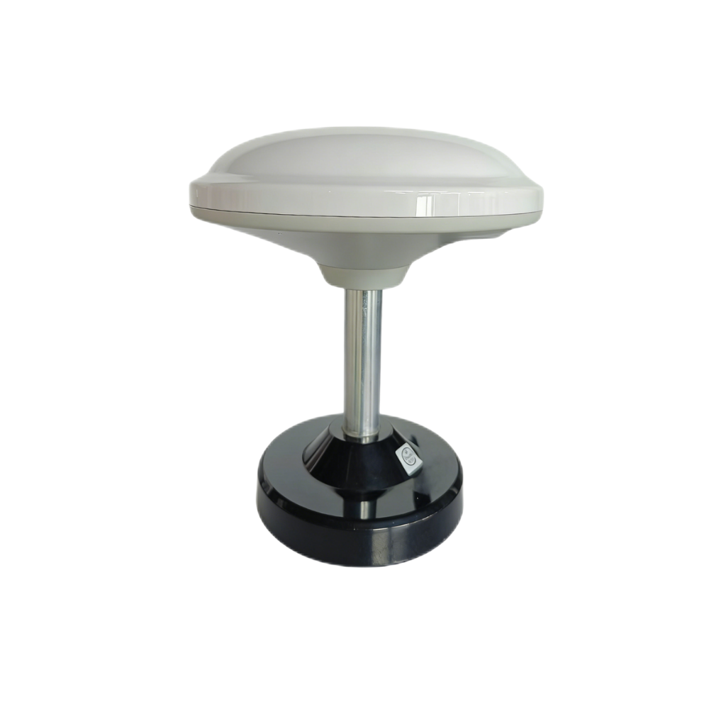 |
 |
| Frequency Band | GPS L1/L5, Beidou B1/B2A/B2I, Galileo E1/E5, QZSS L1/L5, GLONASS G1, IRNSS | GPS L1/L5, BeiDou B1/B2A/B2I, GLONASS G1, Galileo E1/E5, QZSS L1/L5, IRNSS L5 |
| RTK Position Accuracy | H: 1cm + 1ppm, V: 1.5cm + 1ppm | H: 1cm + 1ppm, V: 1.5cm + 1ppm |
| Protocol | NMEA 0183 output and RTCM input at rover side. RTCM output at base side. | NMEA 0183 output and RTCM input at rover side |
| Baud Rate | 115200 bps | 115200 bps |
| Dimensions | Φ152 × 67.9mm | Φ44 × 37mm |
| Weight | <550 g | Not specified in provided data |
| Interface | TTL level UART interface | TTL level UART interface |
| Timing Synchronization Accuracy | 20ns | 20ns |
| Operating Temperature | -40 ℃ – 85 ℃ | -40 ℃ – 85 ℃ |
| Antenna / Housing Feature | Integrated module and antenna; UV-resistant PC material; windproof and rainproof design | L1 and L5 GNSS antenna system with at least 40db high gain; IP67 waterproof |
| Optional Communication | Supports optional 4G radio module | Not specified in provided data |
| Best Fit | Survey-grade UAV mapping, base/rover workflows, outdoor industrial positioning, and larger airframes | Compact UAVs, unmanned vehicles, ships, robotics, and waterproof RTK positioning systems |
Multiband RTK Survey Module HM-D13
The Multiband RTK Survey Module HM-D13 is a rugged integrated RTK survey module for professional drone RTK, field mapping, outdoor robotics, and base-rover positioning workflows. It supports GPS L1/L5, Beidou B1/B2A/B2I, Galileo E1/E5, QZSS L1/L5, GLONASS G1, and IRNSS satellite signals, giving users broad multi-system positioning capability. Its RTK position accuracy is specified as H: 1cm + 1ppm and V: 1.5cm + 1ppm under suitable RTK operating conditions.
The HM-D13 outputs NMEA 0183 and accepts RTCM input at the rover side. It also supports RTCM output at the base side, which makes it relevant for teams building complete base-rover RTK architectures. The module uses a TTL-level UART interface, operates at 115200 bps, provides 20ns timing synchronization accuracy, and supports an optional 4G radio module. Its dimensions are Φ152 × 67.9mm, and its weight is less than 550 g. The product integrates module and antenna in an all-in-one design for stable signal reception and precise positioning. It is made of UV-resistant PC material and is described as windproof and rainproof for harsh outdoor performance.
HM-D13 is a strong fit for survey UAV platforms, mapping payloads, outdoor robots, base-rover workflows, industrial positioning systems, and larger aircraft that can accommodate its physical size. It is especially relevant when a project needs integrated antenna design, broad multiband constellation support, base-side RTCM output capability, and optional 4G radio support.
View Product Details & Pricing ➔
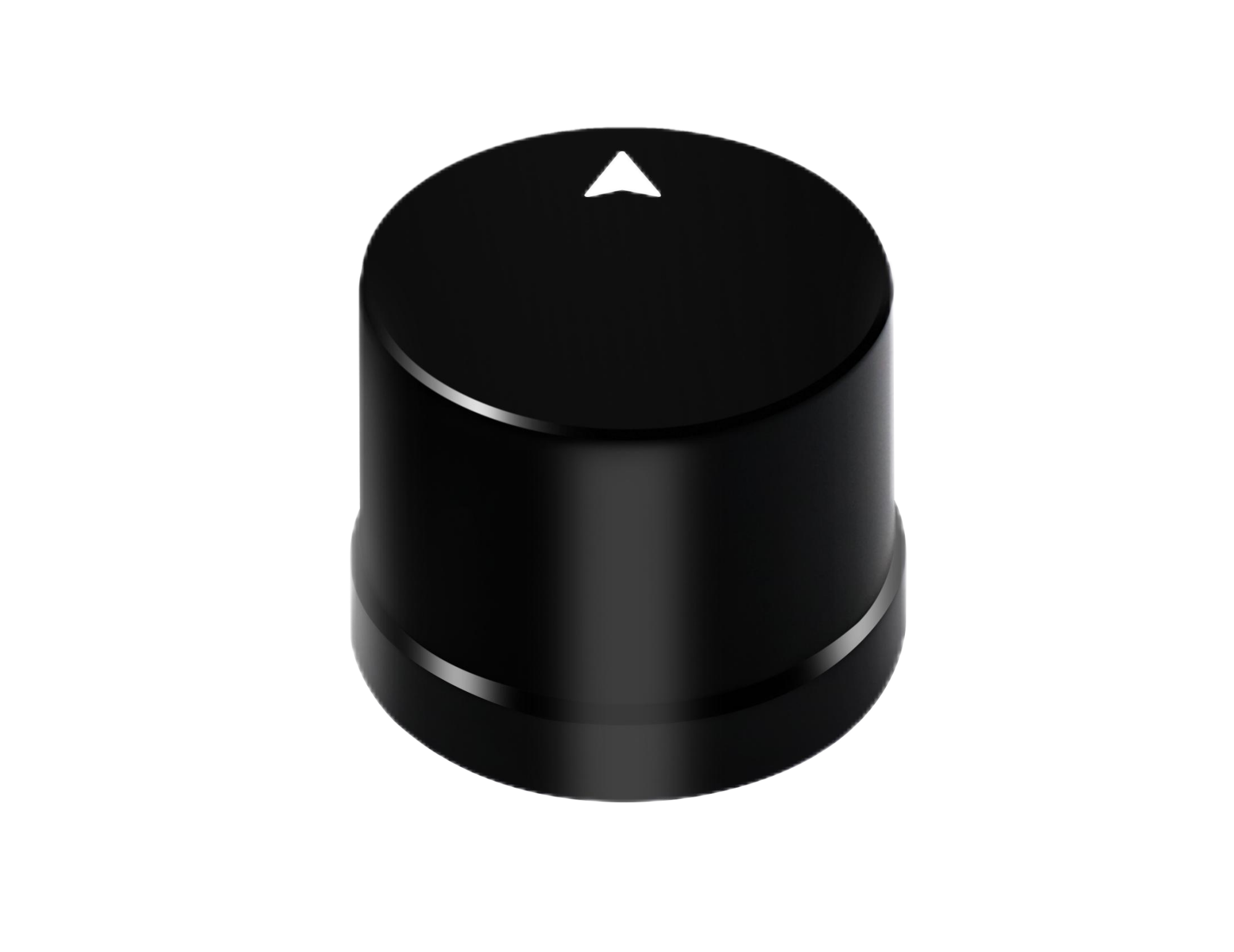
Helical Antenna RTK Module HM-D20
The Helical Antenna RTK Module HM-D20 is a compact integrated helical antenna RTK module designed for UAVs, unmanned vehicles, ships, robotics platforms, and positioning systems that require small size and rugged outdoor performance. It supports GPS L1/L5, BeiDou B1/B2A/B2I, GLONASS G1, Galileo E1/E5, QZSS L1/L5, and IRNSS L5. Its RTK position accuracy is specified as H: 1cm + 1ppm and V: 1.5cm + 1ppm under suitable RTK correction conditions.
The HM-D20 provides NMEA 0183 output and RTCM input at the rover side. It uses a TTL-level UART interface, operates at 115200 bps, and provides 20ns timing synchronization accuracy. Its dimensions are Φ44 × 37mm, making it significantly more compact than larger survey-oriented RTK modules. The product includes an L1 and L5 GNSS antenna system with at least 40db high gain, and the provided data specifies IP67 waterproof performance. Its operating temperature range is -40 ℃ – 85 ℃, making it relevant for outdoor and industrial environments.
HM-D20 is a strong fit for compact drone RTK systems, UAV navigation, unmanned vehicle positioning, marine robotics, outdoor autonomous platforms, and payload-constrained installations. Its integrated design eliminates the need for an external antenna, while its compact helical antenna form factor helps teams reduce mechanical complexity.
View Product Details & Pricing ➔
Drone RTK Implementation Checklist
A disciplined implementation checklist prevents most RTK integration failures. The goal is to confirm that the module, correction workflow, electrical interface, mechanical installation, and software stack all operate correctly before relying on the system in production mapping or autonomous navigation.
Pre-Purchase Checklist
- ✅ Confirm that the module supports the required GNSS constellations and frequency bands.
- ✅ Verify that the module accepts RTCM correction input for rover operation.
- ✅ Check whether the module outputs NMEA 0183 or another required navigation protocol.
- ✅ Confirm flight controller or onboard computer compatibility.
- ✅ Verify UART voltage level, baud rate, and pinout requirements.
- ✅ Check whether module size and weight fit the UAV platform.
- ✅ Decide whether an integrated antenna or external antenna is better for the project.
- ✅ Confirm environmental requirements such as waterproofing, temperature range, and outdoor durability.
- ✅ Identify whether technical support, OEM customization, or ODM customization is needed.
Bench Integration Checklist
- ⚙️ Verify power supply stability before connecting the module to the aircraft system.
- ⚙️ Confirm UART wiring and voltage level compatibility.
- ⚙️ Set serial communication to 115200 bps unless the system has been intentionally reconfigured.
- ⚙️ Parse NMEA output and confirm valid position messages.
- ⚙️ Feed RTCM correction data and monitor RTK status transitions.
- ⚙️ Log satellite count, fix type, correction age, and position output.
- ⚙️ Confirm coordinate frame settings and antenna phase center reference.
- ⚙️ Validate timing behavior if camera triggering, LiDAR, or sensor fusion is involved.
Flight Test Checklist
- ⚙️ Begin testing in open-sky conditions with minimal obstruction.
- ⚙️ Record RTK fixed stability during the full mission.
- ⚙️ Monitor correction age and dropout recovery.
- ⚙️ Fly repeatable grid missions and compare results.
- ⚙️ Check geotag accuracy against known checkpoints where available.
- ⚙️ Validate mapping outputs through the intended photogrammetry workflow.
- ⚙️ Repeat testing under different altitudes, flight speeds, and baseline distances.
- ⚙️ Document configuration settings so the system can be reproduced consistently.
Industrial Applications of Drone RTK
Drone RTK is valuable wherever precise outdoor positioning, repeatable routes, and reliable spatial data are required. It is not limited to traditional land surveying. The same core positioning technology can support aerial mapping, industrial inspection, mobile robotics, autonomous vehicles, ships, and field automation systems.
Surveying and Mapping
Surveying and mapping teams use drone RTK to produce accurate orthomosaics, point clouds, digital surface models, terrain maps, corridor maps, and site documentation. RTK can reduce reliance on dense ground control point networks and improve direct georeferencing. For recurring projects, repeatable positioning also improves comparison between missions.
Precision Agriculture
In agriculture, drone RTK supports repeatable flight paths, crop monitoring, plant counting, row alignment, variable-rate prescription mapping, and field boundary verification. Accurate geotagging allows agronomists and farm managers to compare field conditions over time and return to precise locations for inspection or treatment planning.
Construction and Mining
Construction and mining teams use drone RTK for stockpile measurement, site progress documentation, earthwork comparison, road construction monitoring, and integration with CAD or machine-control data. Accurate repeatable positioning helps teams measure change over time and communicate progress using trusted spatial information.
Powerline, Pipeline, and Solar Inspection
Inspection teams use RTK positioning to improve defect localization, maintenance planning, and repeat inspection workflows. In solar farms, accurate geotagging helps locate damaged panels or underperforming zones. In powerline and pipeline inspection, better position data improves the value of images, thermal data, and inspection records.
Robotics and Autonomous Vehicles
Drone RTK modules can also support unmanned ground vehicles, boats, field robots, and autonomous platforms that require precise outdoor localization. In these systems, GNSS positioning is often combined with IMU, LiDAR, cameras, wheel odometry, or other sensors. GNSS provides global position, while onboard perception supports local awareness, obstacle detection, and motion control.
Drone RTK FAQ
Do I need a separate RTK base station for a drone RTK module?
Can I build my own FPV or mapping drone with RTK if I am new to UAV systems?
Is drone RTK real accuracy or just marketing?
What is the difference between RTK fixed and RTK float?
Which is better for my UAV: HM-D13 or HM-D20?
📚 References & Further Reading
- Industry Standard: SPIE
- Industry Standard: Luminar Technologies
- Related Guide: What Phase Means in 3D Structured Light Cameras
- Related Guide: What Is dToF Solid-State LiDAR?
- Related Product: RISC-V Dev Board HM-RV1
- RTK Product: Multiband RTK Survey Module HM-D13
- RTK Product: Helical Antenna RTK Module HM-D20






