

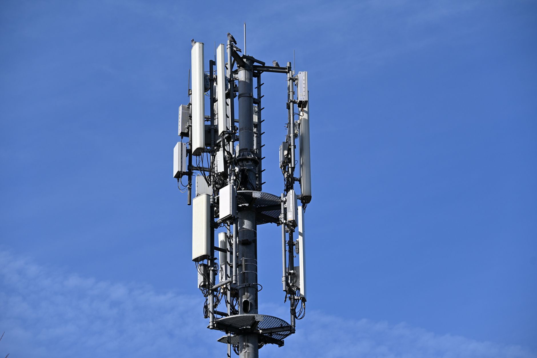
RTK Base Station for Drones, Robots, and Surveying: How to Get Centimeter-Level GNSS Without Subscription Lock-In
Here’s the deal: an rtk base station is often the difference between hardware that is only “RTK-ready” on paper and a field system that actually holds centimeter-level positioning when the job gets messy. Drones, robots, survey rovers, autonomous vehicles, and agricultural machines may already have advanced GNSS receivers onboard, but stable RTK performance depends on more than the rover module. Correction quality, antenna placement, satellite visibility, baseline length, communication reliability, RTCM compatibility, and weather-ready installation all decide whether your system locks into fixed RTK or keeps sliding back into float or standard GNSS.
This guide walks through how to plan, choose, and deploy a subscription-free RTK base station architecture for UAV mapping, outdoor robotics, precision agriculture, surveying, industrial automation, and research platforms. We’ll cover how RTK corrections work, when a dedicated base station beats an NTRIP network, which hardware specs actually matter, how correction data reaches multiple rovers, and how integrated multiband RTK modules such as the HM-D13 and HM-D20 fit into practical industrial deployments.
Table of Contents
- 👉 What Is an RTK Base Station?
- 👉 Why Subscription-Free RTK Matters for Industrial Teams
- 👉 How RTK Corrections Work
- 👉 RTK Base Station vs NTRIP Network
- 👉 RTK System Architecture for Drones, Robots, and Surveying
- 👉 Hardware Requirements for a Reliable RTK Base Station
- 👉 Correction Data Links: Radio, 4G, NTRIP, and UART
- 👉 Accuracy, Error Budget, and Field Reliability
- 👉 Deployment Workflow: From Site Setup to Fixed RTK
- 👉 Recommended RTK Modules and Product Specs
- 👉 Industrial Use Cases for RTK Base Stations
- 👉 RTK Base Station Buying Checklist
- 👉 RTK Base Station FAQ
What Is an RTK Base Station?
Plain-English Definition
An RTK base station is a fixed GNSS receiver placed at a known, surveyed, or repeatable reference location. It listens to satellite signals, compares what it receives against its known position, and produces correction data that helps nearby moving receivers calculate a much more accurate position. Those moving receivers are usually called rovers. In plain shop-floor language, the base station is the trusted local reference point for drones, robots, survey poles, autonomous vehicles, ships, agricultural equipment, and industrial positioning systems.
The base station usually does not steer the rover or calculate the rover’s final position directly. Instead, it broadcasts correction data. Each rover receives satellite signals on its own, receives corrections from the base, and uses both data streams to compute its high-accuracy position. That is why the base station deserves as much attention as the rover receiver. A strong rover connected to a weak correction source is still a weak RTK system.
Base Station vs Rover
The base station is stationary, mounted in a stable location, and configured around a reference coordinate. The rover is mobile and installed on the drone, robot, survey pole, vehicle, machine, or embedded platform that needs accurate positioning. Between them is the correction link. That link may be a radio modem, 4G connection, NTRIP workflow, serial telemetry bridge, local IP network, or UART-based embedded interface.
Look at the base and rover as one system, not two separate parts. If the rover supports RTK but cannot receive compatible RTCM correction messages, it may never reach fixed RTK. If the base has excellent GNSS performance but is sitting under trees, near metal roofing, or on a mount that moves in the wind, correction quality will suffer. If the communication link drops out or runs with high latency, the rover may bounce between fixed RTK, float RTK, and lower-accuracy GNSS modes.
Why RTK Improves GNSS Accuracy
Standard GNSS can drift by meters because satellite positioning is affected by atmospheric delay, satellite orbit error, satellite clock error, receiver noise, multipath reflections, and poor satellite geometry. RTK improves that picture by using carrier-phase measurements and local corrections from a nearby base station. When the rover can resolve carrier-phase ambiguities and maintain a clean correction stream, centimeter-level GNSS becomes realistic under suitable open-sky conditions.
For robots and autonomous systems, that accuracy becomes a reliable global positioning layer. Still, seasoned engineers rarely let RTK work alone. In the shop and out in the field, RTK is often combined with local sensing, odometry, IMU data, visual-inertial odometry, or LiDAR-based perception. If you are designing outdoor autonomy, the related guide on precise robot localization explains why robots often need several localization technologies working together. In broader autonomous systems, GNSS may also be combined with perception technologies such as LiDAR for mapping, obstacle detection, and environmental awareness.
Why Subscription-Free RTK Matters for Industrial Teams
Reducing Recurring Correction Costs
Many professional RTK workflows rely on paid NTRIP correction services. Those networks can be convenient and effective where coverage is available, but the recurring cost adds up quickly when a farm, survey company, UAV operator, robot fleet, university lab, or industrial campus needs multiple devices online every day. A local RTK base station can reduce or eliminate reliance on third-party correction subscriptions for operations that happen repeatedly in the same area.
Subscription-free does not mean zero cost. You still need hardware, installation, power, communication equipment, configuration time, and field verification. The advantage is control. Once the base station is deployed correctly, the team owns the correction source and can decide how corrections are distributed, how many rovers receive them, how access is managed, and how the infrastructure is maintained.
Avoiding Coverage Gaps
Correction networks and cellular coverage are not equally available everywhere. Farms, mines, solar farms, construction sites, ports, coastal operations, research fields, logistics yards, and remote test zones often include weak signal areas. A dedicated local RTK base station can provide correction data where public networks are unreliable or unavailable, as long as the project includes a suitable local communication link.
For UAV mapping and precision agriculture, that control can be the difference between finishing the mission and going home with bad data. Flights may cover wide fields, remote boundaries, or temporary sites. Mobile robots may repeat the same route every day and need the route to line up every time. Survey crews may need predictable control over the job site coordinate workflow instead of hoping a network correction service behaves the same way at every location.
Maintaining Control Over Data and Infrastructure
Industrial teams often need to control more than accuracy. They may need to control reference coordinates, access permissions, correction formats, update rates, security policies, uptime procedures, and diagnostic logs. Owning an RTK base station allows the correction source to become part of the larger autonomy, mapping, or industrial automation stack.
This matters in fleet deployments. A logistics yard with autonomous vehicles, a robotics lab testing multiple rovers, or a farm operating several machines may want one reference infrastructure that supports repeatable positioning across devices. A local base station gives engineers a stable foundation for integration, troubleshooting, long-term maintenance, and operational improvement.
When Subscription-Free Does Not Mean Zero Infrastructure
A subscription-free RTK base station still requires real engineering. The antenna needs clear sky visibility and a stable mount. The base coordinate should be known, surveyed, or at least repeatable depending on the accuracy requirement. The communication link must deliver RTCM corrections reliably. The rover must support the same correction workflow. Power, weather protection, cable management, grounding, and environmental durability all matter.
The most successful deployments treat RTK as infrastructure, not just a receiver purchase. If the base station is installed casually, moved without updating coordinates, or placed near reflective surfaces, the rover may struggle even with good hardware. If the correction stream is intermittent, the rover may lose fixed RTK in the middle of a mission. RTK rewards clean installation and punishes shortcuts.
How RTK Corrections Work
Satellite Signals and Carrier-Phase Measurements
RTK is powerful because it does not rely only on conventional code-phase GNSS positioning. It uses carrier-phase observations, which provide much finer measurement resolution. The base and rover both observe satellite signals. Because the base station is fixed at a known location, it can identify the difference between the expected satellite observations and the actual measured observations. Those differences are encoded into correction messages and sent to the rover.
The rover uses correction data together with its own satellite observations to estimate a precise position. When signal quality, satellite geometry, correction age, baseline length, and receiver processing are favorable, the rover can resolve ambiguities and achieve a fixed RTK solution. Fixed RTK is the state most professional users want because it provides the best stability and accuracy.
RTCM Correction Data
RTCM is a widely used correction message format for RTK systems. A base station outputs RTCM correction messages, and a rover receives RTCM input to improve its position solution. In a practical base-rover system, RTCM compatibility is one of the first things to check. If the base station cannot output RTCM, it may not function as the correction source you need. If the rover cannot accept RTCM input, it may not use the correction stream properly.
The HM-D13 specification is especially relevant for base station workflows because it states: NMEA 0183 output and RTCM input at rover side. RTCM output at base side. That means the module is specified for both rover-side correction reception and base-side correction output. For teams building a local RTK base station, base-side RTCM output is not a nice extra. It is a core requirement.
NMEA Output for Navigation Systems
NMEA 0183 is commonly used to output navigation data such as position, velocity, time, fix quality, satellite information, and GNSS status. Flight controllers, survey controllers, robot computers, embedded processors, and industrial boards often use NMEA messages because they are standardized, readable, and broadly supported.
In an RTK deployment, NMEA and RTCM serve different jobs. RTCM is correction data, typically flowing from the base station or correction source to the rover. NMEA is navigation output, typically flowing from the rover receiver to the controller, autopilot, robot computer, or data logger. A well-designed system checks both sides: the rover must receive corrections, and the controller must correctly interpret the rover’s navigation output.
Why Multiband GNSS Matters
Multiband GNSS improves reliability by allowing the receiver to use multiple frequencies and constellations. Compared with single-frequency GNSS, multiband support can improve fix availability, reduce convergence time, increase robustness near partial obstruction, and help reduce the impact of atmospheric effects and multipath. For drones, robots, and survey rovers operating in real outdoor environments, that matters because sky conditions are rarely perfect.
The HM-D13 supports GPS L1/L5, Beidou B1/B2A/B2I, Galileo E1/E5, QZSS L1/L5, GLONASS G1, and IRNSS. The HM-D20 supports GPS L1/L5, BeiDou B1/B2A/B2I, GLONASS G1, Galileo E1/E5, QZSS L1/L5, and IRNSS L5. Broad constellation coverage helps increase satellite availability, which can improve positioning stability in UAV, robotics, survey, marine, agriculture, and industrial applications.
RTK Base Station vs NTRIP Network
Dedicated RTK Base Station
A dedicated RTK base station is often the right choice for private job sites, UAV mapping fields, farms, robot test zones, construction automation, industrial campuses, ports, and repeated missions over the same location. It gives the operator direct control over the reference receiver, antenna placement, correction output, and local distribution method. For closed-loop industrial operations, that control can be more valuable than depending on an external correction provider.
The benefits are straightforward: no recurring correction subscription, full control over hardware and coordinates, local availability in areas with weak network service, and the ability to support multiple rovers if the communication architecture allows it. The limitations are real too. You need proper setup, a stable base location, power, a correction link, a suitable antenna environment, and a reference coordinate strategy. Accuracy depends on base coordinate quality, baseline length, satellite visibility, and correction delivery.
NTRIP Correction Network
NTRIP delivers correction data over the internet from a correction network, caster, or base station feed. It is convenient for mobile teams that operate across large regions and do not want to deploy a local base each time. Where network coverage is strong and subscriptions are acceptable, NTRIP can be an efficient choice for survey crews, vehicle fleets, and UAV operators.
The tradeoffs are subscription cost, cellular dependency, regional coverage, data plan requirements, and reduced control over the correction infrastructure. If a project operates in a remote field, under strict data policies, or in a controlled industrial environment, a local base station may be preferred. Many advanced teams support both workflows so they can use NTRIP when convenient and a local RTK base station when control and availability matter most.
Hybrid Workflow
A hybrid workflow combines local RTK base station corrections with NTRIP capability. A survey company may use NTRIP in urban areas and deploy a local base for remote jobs. A robotics lab may use a fixed local base for testing but support NTRIP for field demonstrations. A farm may operate its own base station while keeping network corrections as a backup.
This flexibility is useful because RTK performance is strongly influenced by environment and operations. The best architecture is not always one method forever. It is the method that reliably delivers correction data to the rover under your actual field conditions.
RTK System Architecture for Drones, Robots, and Surveying
Core Architecture
A complete RTK system includes GNSS satellites, a base station, a correction data link, a rover RTK module, a controller or compute system, and navigation software. The base station receives satellite signals and outputs corrections. The correction link transports RTCM data. The rover receives both satellites and corrections. The controller or robot computer receives navigation output and uses it for mapping, navigation, control, logging, or sensor fusion.
Every layer must be compatible. The GNSS receiver must support the required constellations and frequencies. The base must output the correction format required by the rover. The communication link must preserve message timing. The rover output must match the controller interface. A small mismatch in baud rate, message type, wiring, voltage level, or correction format can prevent fixed RTK even when the hardware spec sheet looks strong.
Drone Mapping Architecture
In drone mapping, RTK corrections can support accurate image geotagging, precise waypoint navigation, repeatable flight paths, and reduced dependence on ground control points. The rover module may connect to the flight controller, mission computer, or payload timing system. Accurate GNSS time and position data can help align images, flight logs, and mapping outputs.
For UAV teams, mechanical installation matters as much as configuration. The antenna should sit where it has good sky visibility and minimal electromagnetic interference. The communication link must remain stable during flight. If corrections are sent by radio, range and antenna orientation matter. If corrections are sent over cellular or NTRIP, coverage and latency should be validated before production missions, not after a failed flight.
Mobile Robot and AMR Architecture
Outdoor mobile robots often use RTK as the global localization layer while relying on other sensors for local motion estimation and obstacle awareness. Wheel odometry, IMU data, visual-inertial odometry, and LiDAR can provide short-term stability and environmental perception. RTK helps anchor the robot to a global coordinate system, which is valuable for route repeatability, fleet operations, field mapping, and outdoor autonomy.
When designing robotic localization, RTK should be treated as one source in a sensor fusion stack. Visual-inertial systems can help bridge short GNSS disturbances, and the guide on building VIO and VSLAM systems is useful for teams combining camera and IMU data. For perception and obstacle detection, LiDAR sensors for robotics can complement GNSS-based positioning. Industrial perception sensors such as Sony’s LiDAR-related sensing products show how autonomy platforms often combine positioning and perception instead of betting everything on one sensor type.
Surveying Architecture
In surveying, a base station may be placed over a known control point or configured through a survey-in process. The rover then collects coordinates in the field while receiving corrections. The workflow can support topographic surveys, construction layout, boundary work, control verification, and site documentation.
Survey teams should pay close attention to coordinate systems, base coordinates, antenna height, phase center behavior, and repeatability. A local base station can provide excellent relative accuracy across a site, but absolute accuracy depends on how accurately the base position is known. For temporary setups, field procedures should document the base location, antenna height, setup time, and correction settings.
Multi-Rover Architecture
One RTK base station can support multiple rovers if its corrections are distributed through a compatible communication system. The base station broadcasts reference correction data. Each rover receives the same corrections and calculates its own position. This architecture is useful for drone fleets, robot fleets, multiple survey crews, agricultural machines, unmanned vehicles, and industrial campuses.
The practical limit depends on the correction link. A radio broadcast may serve several receivers within range. A 4G or NTRIP-style workflow may support wider distribution over IP networks. A direct UART workflow is usually more point-to-point and better suited to embedded systems or local integration. Fleet deployments should validate latency, correction age, bandwidth, update rate, rover compatibility, and failover behavior.
Hardware Requirements for a Reliable RTK Base Station
Multiband GNSS Receiver
A reliable RTK base station should use a multiband GNSS receiver. L1/L5 and multi-frequency support help reduce susceptibility to atmospheric errors and improve fix stability. Multiband capability is especially important for industrial applications where uptime and repeatability matter more than occasional best-case accuracy.
Multi-Constellation Support
GPS-only positioning is not ideal for many professional deployments. Multi-constellation support increases the number of satellites available to the receiver, which can improve geometry and resilience in partial obstruction. Support for GPS, BeiDou, Galileo, GLONASS, QZSS, and IRNSS is valuable for global and regional use cases.
Integrated or External Antenna
Integrated antenna designs simplify installation by reducing cabling, connector mismatch, and antenna selection complexity. External antenna setups may provide more placement flexibility, especially when the receiver must be housed separately from the antenna. Rugged integrated modules are often attractive for drones, unmanned vehicles, outdoor robots, and temporary survey systems because they reduce the number of components that must be mounted and protected.
The HM-D13 uses an integrated module and antenna with a mushroom-shaped GNSS antenna design. Its product details describe stable signal reception, centimeter-accurate positioning, UV-resistant PC material, and outdoor performance with windproof and rainproof characteristics. The HM-D20 uses a compact helical antenna design with an integrated GNSS module and antenna, plus an IP67 waterproof rating.
RTCM Output Capability
Base-side RTCM output is essential for a true local RTK base station workflow. Without RTCM output, the hardware may still be useful as a rover or navigation receiver, but it may not serve as the correction source for other devices. This is why the HM-D13 specification is important: it explicitly includes RTCM output at the base side, making it the stronger fit for base station applications among the two provided products.
UART and Embedded Integration
TTL-level UART is widely used in embedded GNSS integrations. Both HM-D13 and HM-D20 list a TTL level UART interface and a baud rate of 115200 bps. This makes them suitable for connection to embedded systems, flight controllers, robot computers, industrial controller boards, and custom electronics where serial communication is preferred.
Environmental Durability
Outdoor RTK systems must survive real field conditions. Temperature, water exposure, UV exposure, vibration, dust, mounting stress, and cable strain can all affect long-term reliability. Both modules specify an operating temperature range of -40 ℃ to 85 ℃. The HM-D20 specifies IP67 waterproof protection. The HM-D13 product information describes UV-resistant PC material, windproof and rainproof design characteristics, and a weight of less than 550 g.
Correction Data Links: Radio, 4G, NTRIP, and UART
Radio Link
Radio links are common for local correction broadcasting in farms, construction sites, survey fields, drone mapping areas, and industrial yards. A radio workflow can be subscription-free and independent of cellular networks. Radio range depends on transmit power, frequency, antenna height, terrain, interference, obstructions, and local regulatory requirements.
4G or Cellular Link
4G or cellular correction links are useful when rovers operate across a wider area or when multiple devices need IP-based correction access. Cellular workflows can support fleet operations, remote monitoring, and NTRIP-like correction distribution. The HM-D13 product details state that it supports an optional 4G radio module, which can be important for teams planning wider correction distribution or mobile infrastructure.
NTRIP Caster Workflow
A local base station can feed correction data to an NTRIP caster, allowing multiple rovers to receive corrections over an IP connection. This combines the control of a local base with the flexibility of internet-based correction distribution. It is especially useful for campuses, industrial sites, robot fleets, or survey teams that want centralized correction management.
Direct UART Workflow
Direct UART integration is useful for embedded projects, lab systems, flight controllers, and custom robot platforms. In this workflow, RTCM input flows to the rover module and NMEA output flows to the controller or compute system. Engineers should confirm baud rate, voltage level, message configuration, and cable integrity. At 115200 bps, both HM-D13 and HM-D20 align with common embedded serial workflows.
Choosing the Right Link
The best correction link depends on range, number of rovers, infrastructure, environmental conditions, and operational risk. Short-range field work often fits radio. Fleet operation across a cellular network may fit 4G or NTRIP. Embedded local systems may fit UART. Lab and test areas may use IP bridges where available. Harsh industrial sites may require rugged radios, managed networks, or redundant correction paths.
Accuracy, Error Budget, and Field Reliability
Understanding 1 cm + 1 ppm Accuracy
The HM-D13 and HM-D20 both list RTK position accuracy as horizontal 1 cm + 1 ppm and vertical 1.5 cm + 1 ppm. The ppm component means baseline distance contributes to the error budget. As the rover moves farther from the base, atmospheric differences and distance-related uncertainty can increase. Vertical positioning is typically less precise than horizontal positioning, which is reflected in the listed vertical specification.
Open-Sky vs Obstructed Environments
RTK performs best with open-sky satellite visibility. Trees, buildings, metal roofs, vehicles, cranes, power lines, and reflective surfaces can reduce satellite quality or introduce multipath. In obstructed environments, the rover may take longer to reach fixed RTK or may move between fixed and float states. Industrial teams should test in their real operating area instead of relying only on open-field specifications.
Multipath and Antenna Placement
Multipath occurs when GNSS signals reflect from nearby surfaces before reaching the antenna. These reflected signals can distort measurements and reduce positioning stability. Base stations should be mounted in a stable, open location away from reflective structures where possible. Antenna placement should be repeatable, secure, and documented, especially for survey and industrial operations that require consistent coordinates over time.
Baseline Length
Shorter base-rover baselines generally improve RTK reliability because atmospheric conditions are more similar at the base and rover. Long baselines can increase atmospheric decorrelation and reduce fixed solution stability. When planning an RTK base station, teams should consider not only the maximum communication range but also the distance at which they expect reliable centimeter-level positioning.
Timing Synchronization
Both HM-D13 and HM-D20 list timing synchronization accuracy of 20ns. Timing can be important for UAV mapping payloads, sensor fusion, robotics, and systems that align GNSS data with camera, LiDAR, IMU, or control logs. Accurate timing helps engineers correlate data streams and build more reliable navigation or mapping outputs.
Deployment Workflow: From Site Setup to Fixed RTK
Step 1: Choose the Base Station Location
Select a stable location with clear sky visibility and minimal obstruction. Avoid reflective surfaces, unstable tripods, vibration, and nearby sources of interference. If the base station is permanent, invest in a secure mount and documented coordinates. If it is temporary, use repeatable setup procedures and record antenna height, location, and configuration.
Step 2: Configure Base Mode
Configure the receiver for base station operation using a known coordinate or survey-in workflow depending on project requirements. For high absolute accuracy, a surveyed coordinate is preferred. For repeatable relative positioning across a local site, a consistent base coordinate may be sufficient. Confirm that the base is outputting the required RTCM messages.
Step 3: Configure the Correction Link
Choose radio, 4G, NTRIP, UART, or another transport method based on rover count, operating range, infrastructure, and environmental conditions. Validate that correction messages reach the rover reliably and that correction age remains acceptable during real movement, not only during bench testing.
Step 4: Configure the Rover
Configure the rover to accept RTCM input and output navigation data in the required format. Confirm baud rate, serial voltage level, wiring, message type, and update behavior. If the rover connects to a flight controller, robot computer, or survey controller, verify that the controller recognizes RTK fix status and uses the corrected position correctly.
Step 5: Verify RTK Fix
Monitor fix type, satellite count, correction age, baseline distance, and position stability. A receiver may report autonomous GNSS, differential GNSS, float RTK, or fixed RTK. Fixed RTK is the target for centimeter-level operation. If the rover remains in float RTK or repeatedly loses fix, investigate antenna placement, satellite visibility, correction latency, baseline length, and message compatibility.
Step 6: Validate Against Ground Truth
Before relying on RTK for production, validate against known control points, repeated passes, mission logs, or independent measurements. For drones, check image geotags and mapping outputs. For robots, verify route repeatability and localization consistency. For survey applications, compare against control points and document procedures.
Recommended RTK Modules and Product Specs
The right RTK base station or rover module depends on physical installation, environmental exposure, communication needs, antenna design, and whether base-side RTCM output is required. Based on the provided specifications, the HM-D13 is the stronger fit for RTK base station workflows because its protocol specification explicitly includes RTCM output at the base side. The HM-D20 is a compact, rugged RTK module option for rover-side installations, UAVs, unmanned vehicles, ships, and mobile positioning systems where IP67 protection and a helical antenna design are valuable.
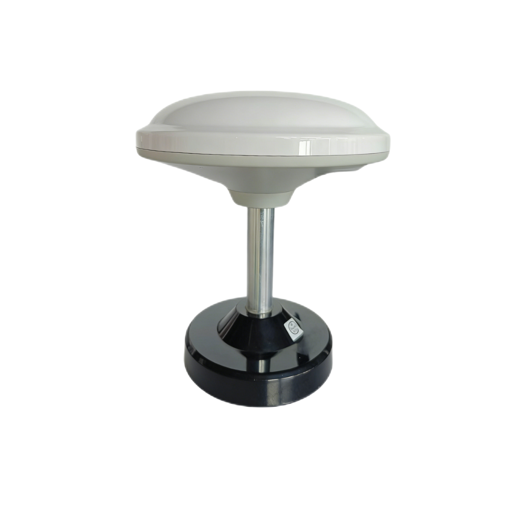
Multiband RTK Survey Module HM-D13
The HM-D13 is a multiband RTK survey module with an integrated mushroom-shaped GNSS antenna design. It is well suited for RTK base station, survey reference, UAV correction infrastructure, robot positioning infrastructure, and industrial autonomy workflows where base-side RTCM correction output is required.
Its provided specification includes GPS L1/L5, Beidou B1/B2A/B2I, Galileo E1/E5, QZSS L1/L5, GLONASS G1, and IRNSS support. It lists RTK position accuracy of H: 1cm + 1ppm and V: 1.5cm + 1ppm, NMEA 0183 output and RTCM input at rover side, RTCM output at base side, 115200 bps baud rate, TTL level UART interface, 20ns timing synchronization accuracy, -40 ℃ to 85 ℃ operating temperature, dimensions of Φ152*67.9mm, and weight less than 550 g.
The product details describe integrated modules and antennae for stable signal reception, centimeter-accurate positioning, UV-resistant PC material, windproof and rainproof outdoor performance, and optional 4G radio module support. These characteristics make it especially relevant when a team wants to build controlled local correction infrastructure rather than depending only on external correction networks.
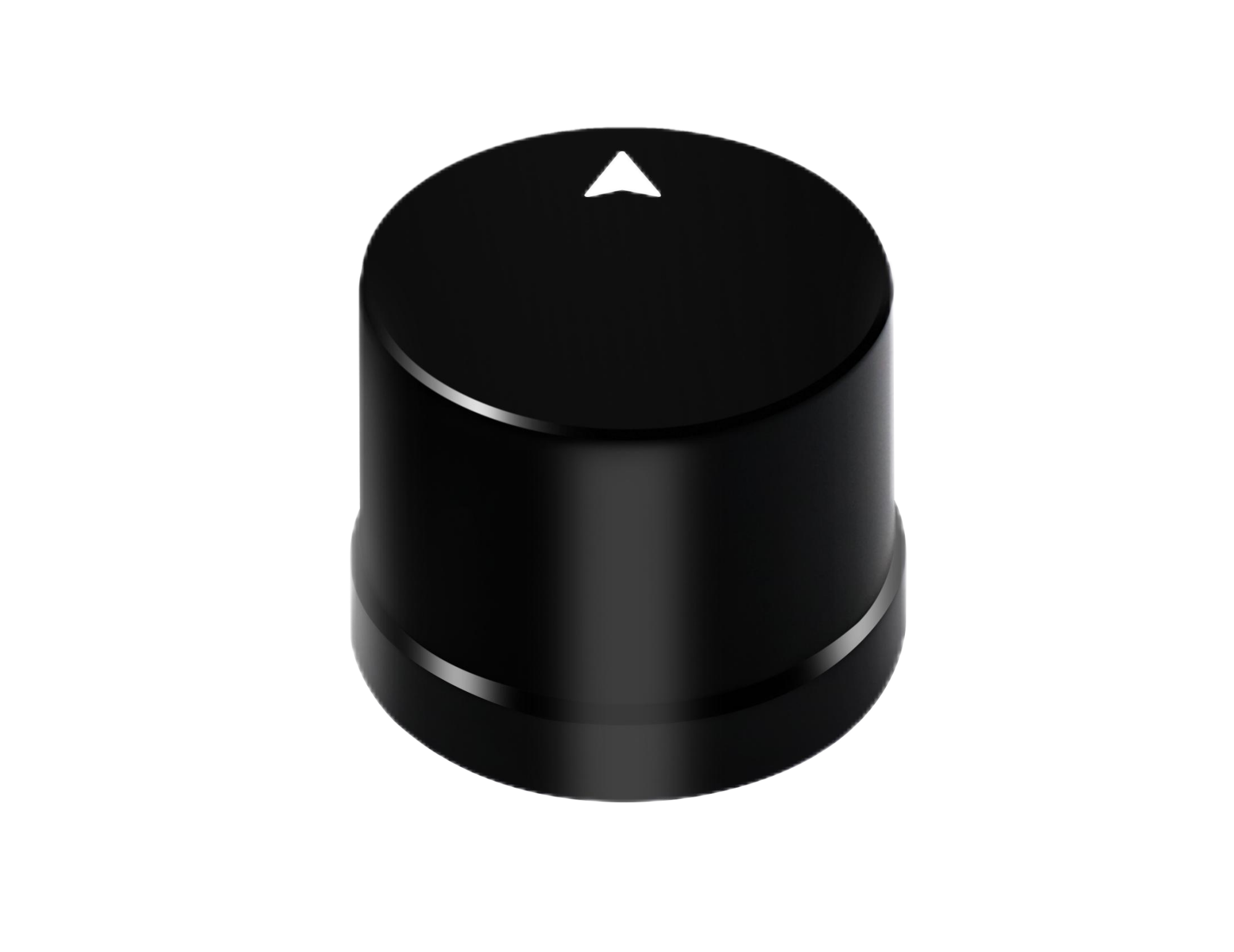
Helical Antenna RTK Module HM-D20
The HM-D20 is a compact helical antenna RTK module designed for UAVs, unmanned vehicles, ships, mobile robots, and positioning systems that need an integrated GNSS module and antenna. It is best positioned as a compact rover-side RTK module where small dimensions, high-gain antenna performance, and waterproof protection are important.
Its provided specification includes GPS L1/L5, BeiDou B1/B2A/B2I, GLONASS G1, Galileo E1/E5, QZSS L1/L5, and IRNSS L5 support. It lists RTK position accuracy of H: 1cm + 1ppm and V: 1.5cm + 1ppm, NMEA 0183 output and RTCM input at rover side, 115200 bps baud rate, TTL level UART interface, dimensions of Φ44*37mm, timing synchronization accuracy of 20ns, -40 ℃ to 85 ℃ operating temperature, IP67 waterproof protection, and an L1/L5 GNSS antenna system with at least 40db high gain.
The product details describe integrated design, plug-and-play installation, high precision positioning, suitability for drones and autonomous vehicles, and rugged waterproof construction for harsh weather conditions. For systems where the rover needs a compact, protected RTK receiver and integrated antenna, the HM-D20 is a practical option.
| Specification | Multiband RTK Survey Module HM-D13 | Helical Antenna RTK Module HM-D20 |
|---|---|---|
| Product URL | HM-D13 Product Page | HM-D20 Product Page |
| Frequency band | GPS L1/L5, Beidou B1/B2A/B2I, Galileo E1/E5, QZSS L1/L5, GLONASS G1, IRNSS | GPS L1/L5, BeiDou B1/B2A/B2I, GLONASS G1, Galileo E1/E5, QZSS L1/L5, IRNSS L5 |
| RTK position accuracy | H: 1cm + 1ppm, V: 1.5cm + 1ppm | H: 1cm + 1ppm, V: 1.5cm + 1ppm |
| Protocol | NMEA 0183 output and RTCM input at rover side. RTCM output at base side. | NMEA 0183 output and RTCM input at rover side |
| Baud Rate | 115200 bps | 115200 bps |
| Interface | TTL level UART interface | TTL level UART interface |
| Dimensions | Φ152*67.9mm | Φ44*37mm |
| Weight | <550 g | Not specified in provided data |
| Timing synchronization accuracy | 20ns | 20ns |
| Operating Temperature | -40 ℃ – 85 ℃ | -40 ℃ – 85 ℃ |
| Antenna / GNSS design | Integrated module and antenna, mushroom-shaped GNSS antenna design | Integrated GNSS module and antenna, L1 and L5 GNSS antenna system with at least 40db high gain |
| Waterproof / outdoor protection | UV-resistant PC material, windproof and rainproof design described in product details | IP67 waterproof |
| Communication option | Supports optional 4G radio module | Not specified in provided data |
| Recommended role | RTK base station or survey reference module where base-side RTCM output is required | Compact rover-side RTK module for UAVs, unmanned vehicles, ships, and positioning systems |
Need RTK Integration Support?
Need a subscription-free RTK base station or rover module for drones, robots, surveying, or industrial autonomy? Compare the HM-D13 and HM-D20 RTK modules or contact the team for integration support based on your rover type, correction link, baseline distance, and operating environment.
View HM-D13 RTK Survey Module
View HM-D20 Helical Antenna RTK Module
Industrial Use Cases for RTK Base Stations
UAV Mapping and Photogrammetry
RTK improves UAV mapping by providing more accurate image geotags, supporting repeatable flight paths, and reducing dependence on dense ground control point networks. A local RTK base station is valuable when drone operators repeatedly map farms, construction sites, mines, solar farms, or industrial campuses. It helps standardize correction availability across missions.
Precision Agriculture
Precision agriculture applications include field boundary mapping, crop scouting, spraying, autonomous tractors, implement guidance, and multi-machine coordination. A subscription-free base station can reduce recurring correction costs across farm operations and improve local control over positioning infrastructure.
Mobile Robots and Outdoor AMRs
Outdoor AMRs, inspection robots, delivery robots, research rovers, and autonomous utility platforms can use RTK as a global positioning input. When combined with IMU, odometry, VIO, or LiDAR, RTK helps provide repeatable outdoor localization. For more context, review the guide on precise robot localization made easy.
Surveying and Construction Layout
Survey and construction teams use RTK for control points, topographic surveys, staking, grading, machine guidance, layout, and site verification. A local base station helps create a consistent correction source for job sites where repeatable accuracy and control over coordinates are essential.
Ports, Logistics Yards, and Industrial Campuses
Ports, logistics yards, and industrial campuses may deploy correction infrastructure for autonomous vehicles, inspection robots, container handling systems, security patrol robots, and asset tracking. A local RTK base station can support multiple rovers if the correction distribution architecture is designed correctly.
Research and Development Platforms
Universities, robotics labs, and autonomy startups often benefit from correction infrastructure they can control and modify. A local RTK base station allows teams to test algorithms, compare sensors, evaluate fusion strategies, and support repeated experiments without depending entirely on paid external networks.
RTK Base Station Buying Checklist
Must-Have Technical Specs
- ✅ Multiband GNSS support for improved field reliability.
- ✅ Multi-constellation tracking across GPS, BeiDou, Galileo, GLONASS, QZSS, and IRNSS where available.
- ✅ Base-side RTCM output for local correction generation.
- ✅ Rover-side RTCM input for corrected positioning.
- ✅ NMEA output for controllers, autopilots, robot computers, and data loggers.
- ✅ Stable UART or industrial interface support.
- ✅ Outdoor operating temperature range and rugged antenna design.
- ✅ Timing synchronization support for mapping, robotics, and sensor fusion.
- ✅ Clear documentation and technical support for integration.
Deployment Questions to Ask
- ⚙️ Will the base station be permanent or temporary?
- ⚙️ How many rovers must receive corrections?
- ⚙️ Is radio, 4G, NTRIP, or UART the best correction link?
- ⚙️ What is the expected baseline length?
- ⚙️ Is the antenna location open-sky and stable?
- ⚙️ Does the rover controller accept RTCM corrections?
- ⚙️ Does the system require ROS, Python, C++, or embedded integration?
- ⚙️ Is IP-rated waterproof protection required?
- ⚙️ Is subscription-free operation mandatory?
Red Flags
- ⚠️ No clear RTCM correction support.
- ⚠️ Single-frequency GNSS for professional RTK applications.
- ⚠️ No base-side correction output for base station use.
- ⚠️ Weak environmental protection for outdoor deployment.
- ⚠️ Poor documentation for embedded integration.
- ⚠️ Unclear antenna phase center behavior.
- ⚠️ No support for multi-constellation tracking.
- ⚠️ No technical support for integration and troubleshooting.
RTK Base Station FAQ
Do I really need an RTK base station if my drone or robot already has an RTK module?
Can I build a subscription-free RTK base station for my farm, drone fleet, or robot system?
Can one RTK base station support multiple rovers, drones, or autonomous devices?
What is the difference between fixed RTK and float RTK?
How far can a rover be from an RTK base station?
Does an RTK base station need to be surveyed?
What correction format should I use for an RTK base station?
Can RTK work indoors?
What causes RTK fix loss?
Is L1/L5 better than L1-only RTK?
How should I choose between HM-D13 and HM-D20?
📚 References & Further Reading
- Industry Standard: LiDAR overview for autonomous perception context
- Related Guide: Precise Robot Localization Made Easy
- Related Guide: Build VIO and VSLAM Systems
- Related Guide: LiDAR Sensors for Robotics






