


LiDAR Definition: What It Is, How It Works, and How to Choose the Right Sensor
LiDAR, short for Light Detection and Ranging, is a sensing technology that uses laser light to measure distance and build a structured understanding of physical space. Here’s the deal: LiDAR gives machines something they badly need in the real world, which is reliable distance information. It sends out light, receives the reflected return signal, and converts that timing information into distance, depth, or 3D point data.
That basic lidar definition sounds simple enough, but anyone who has worked around robots, UAVs, inspection rigs, or automation equipment knows the details make or break the system. Range, accuracy, field of view, frame rate, interface, power consumption, mounting constraints, and environmental tolerance all decide whether the sensor performs well once it leaves the bench and gets put into actual service.
For engineers, buyers, and product teams, the real question is not only what LiDAR means. The better question is which LiDAR architecture fits the job. A compact dToF solid-state module may be a smart match for mobile robots, drones, and embedded systems, while larger mapping or surveying platforms may call for a different LiDAR design entirely.
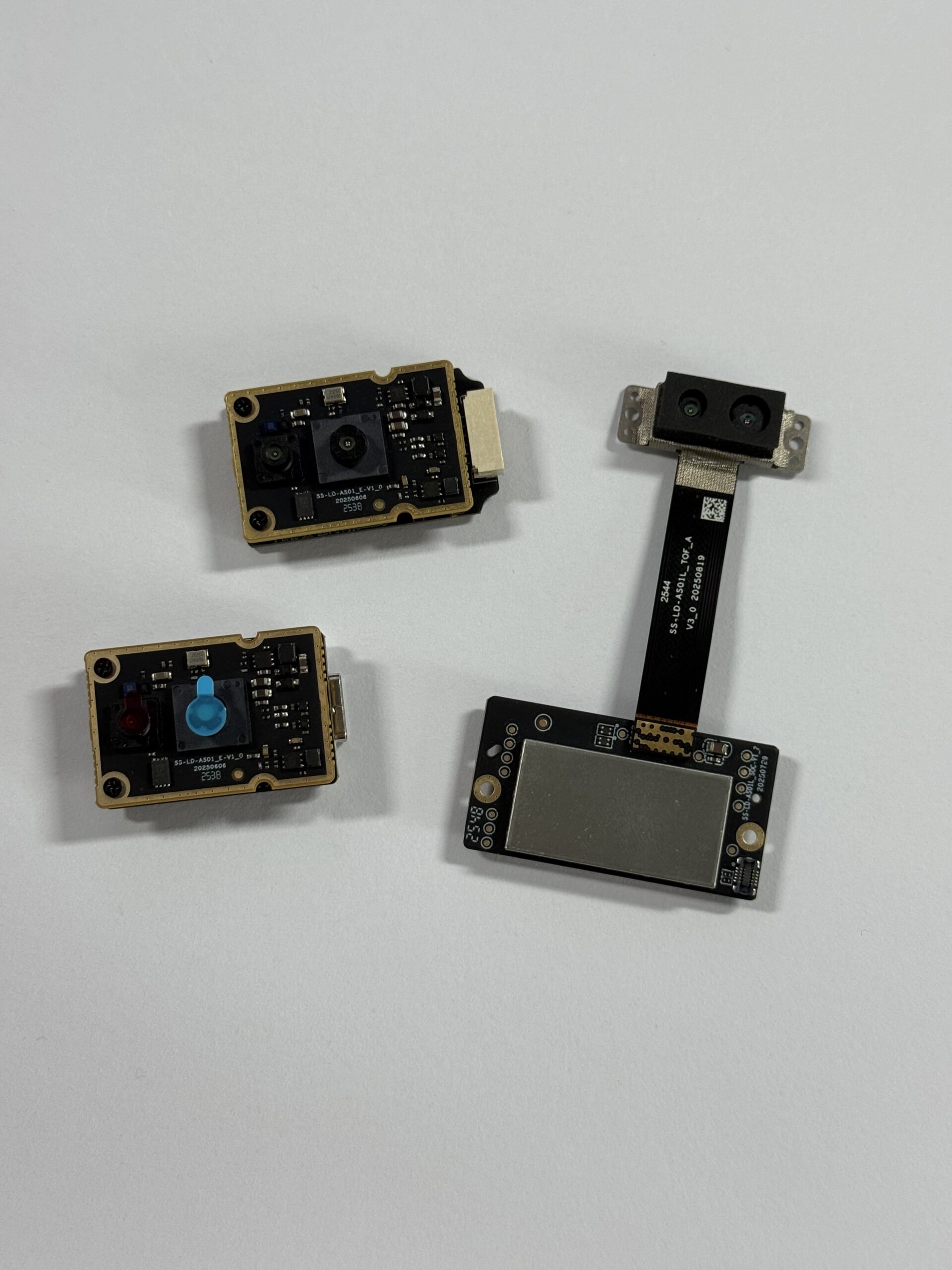
This guide walks through how LiDAR works, how it compares with cameras, radar, ultrasonic sensors, and photogrammetry, which specifications matter most, and how the DTOF Solid State LiDAR HM-LD1 fits modern perception systems. Look, the goal is not to chase the longest spec sheet. The goal is to choose a sensor that actually works in the machine, in the environment, and under the workload you care about.
Table of Contents
- 👉 What Is LiDAR?
- 👉 Why LiDAR Matters in Industrial Automation
- 👉 How LiDAR Works
- 👉 Main Types of LiDAR Technology
- 👉 LiDAR Data Output: Distance, Depth Maps, and Point Clouds
- 👉 LiDAR vs Cameras, Radar, Ultrasonic Sensors, and Photogrammetry
- 👉 LiDAR Applications in Robots, Drones, and Industrial Systems
- 👉 Key LiDAR Specifications to Compare
- 👉 DTOF Solid State LiDAR HM-LD1 Product Showcase
- 👉 How to Choose the Right LiDAR Sensor
- 👉 LiDAR Integration Considerations for Engineers
- 👉 Common Mistakes When Selecting LiDAR
- 👉 Recommended On-Page SEO Elements
- 👉 LiDAR FAQ
- 👉 Final Thoughts: Turning a LiDAR Definition Into a Sensor Decision
What Is LiDAR?
LiDAR stands for Light Detection and Ranging. It is an active optical sensing technology that measures distance by emitting laser light and analyzing the reflected return signal. In a time-of-flight system, the sensor calculates how long it takes for light to travel to a target and return, then converts that time into distance. Depending on the sensor design, the result can be a single range reading, a depth map, or a 3D point cloud.
The plain-English lidar definition is this: LiDAR is a way for machines to measure the shape and distance of the world using light. Unlike a camera, which passively records reflected ambient light, LiDAR actively sends out its own signal. That difference matters in the shop, on a drone, and inside a robot because LiDAR can provide direct geometric information even when color, texture, or scene contrast are poor. For a deeper practical introduction to compact dToF sensing, see this overview of the HM-LD1 solid-state LiDAR module.
In industrial environments, LiDAR is used for obstacle avoidance, navigation, mapping, inspection, safety monitoring, and robotic perception. It is especially valuable where systems need repeatable distance measurement rather than only visual appearance. That is why LiDAR shows up in autonomous mobile robots, UAVs, smart cameras, security devices, and machine vision systems that need dependable spatial awareness.
Why LiDAR Matters in Industrial Automation
Modern automation depends on accurate sensing. A robot moving through a warehouse, a drone following terrain, or an inspection device measuring infrastructure all need a way to understand space. Cameras provide rich visual data, IMUs track motion, and GNSS or RTK can provide positioning, but LiDAR contributes something different: direct measurement of geometry.
That matters because many industrial tasks cannot be solved by appearance alone. A pallet edge, a wall, a bridge support, a landing zone, or a narrow obstacle may not be easy to identify from image data in every lighting condition. LiDAR reduces dependence on texture and color, and it helps machines detect physical objects in low-contrast or repetitive environments.
Look at a typical warehouse aisle. You may have shrink wrap, matte cardboard, glossy labels, forklifts, people, racks, and changing light throughout the day. A camera sees the scene, but the control system still needs to know where the objects are. LiDAR gives the machine measured distance data it can use for stopping, steering, mapping, docking, or triggering a safety response.
LiDAR also helps bridge the gap between human perception and machine control. Humans can glance at a space and judge distance intuitively. Machines need structured numbers. LiDAR turns physical space into measurable data so that robots can stop, turn, map, inspect, or land with greater confidence. If you are evaluating navigation stacks for autonomous machines, this RTK module guide is useful context for how distance sensing and positioning can work together.
From Human Vision to Machine Perception
Human vision is flexible, but it is also subjective. Automation systems need repeatable outputs. LiDAR provides spatial measurements that are easier to feed into control logic, mapping algorithms, and safety systems. Instead of asking a machine to infer everything from appearance, LiDAR gives it measurable structure.
Why Direct Distance Measurement Matters
Direct distance measurement is valuable because it is not built on color interpretation or image matching alone. A system may still need cameras for classification or semantic understanding, but LiDAR tells the machine where something is. That makes it highly useful for collision avoidance, autonomous movement, and inspection applications where the machine must respond to geometry, not just appearance.
Industrial Use Cases That Depend on LiDAR
Common use cases include autonomous mobile robots, UAV altitude hold and terrain following, warehouse automation, smart security, bridge and dam inspection, object recognition, volume measurement, SLAM, and robotic vision development. In every case, the core benefit is the same: the machine gains measurable awareness of surrounding space.
How LiDAR Works
LiDAR works by emitting laser light toward a target and measuring the returned signal after that light reflects from an object. The basic process is straightforward, but the engineering behind it is precise. The sensor must emit light, capture a weak reflection, reject noise, and calculate distance fast enough to support real-time decisions.
In a direct time-of-flight system, the sensor measures the time between emission and return. Because the speed of light is known, distance can be derived from the round-trip travel time. The principle is simple, but timing resolution, detector sensitivity, optical design, filtering, and processing determine whether the system performs well outside a controlled lab.
Step 1: The Sensor Emits Laser Light
⚙️ The transmitter emits a controlled beam or pulse of light. Depending on the architecture, the signal may be pulsed, scanned, or modulated. In dToF systems, short pulses are commonly used because the system directly measures the travel time of the return signal. Optical output, beam shape, and timing control all influence performance at different ranges and under different lighting conditions.
Step 2: Light Reflects From Objects
⚙️ Once emitted, the light travels through air, hits a surface, and some portion of it returns toward the sensor. The strength of that reflection depends on distance, target material, surface angle, reflectivity, and background illumination. Bright, dark, glossy, matte, angled, and transparent surfaces can all behave differently.
Step 3: The Receiver Detects the Return Signal
⚙️ The receiver captures the reflected light. In advanced compact modules, SPAD-based sensing can be used to detect extremely weak return signals. SPAD stands for single-photon avalanche diode, and it is useful in direct time-of-flight designs because it can register tiny amounts of returned light very quickly.
Step 4: Time-of-Flight Becomes Distance
⚙️ The core logic is that distance equals the speed of light multiplied by the round-trip time, divided by two. The division by two matters because the light travels to the target and back. This is the fundamental reason LiDAR can provide direct geometric measurement instead of indirect visual inference.
Step 5: Data Becomes Depth or 3D Output
⚙️ Once the system has distance measurements across multiple directions or pixels, it can build a depth map or point cloud. A depth map is a structured grid of distance values, while a point cloud is a 3D representation of surfaces in space. The DTOF Solid State LiDAR HM-LD1 uses SPAD dToF technology and supports real-time depth images and 3D point cloud data, making it suitable for embedded perception and navigation.
For broader industry context, companies such as Ouster have helped mainstream digital LiDAR architectures in robotics and industrial sensing.
Main Types of LiDAR Technology
LiDAR is not one single product category in practice. Different architectures trade off size, cost, range, density, field of view, and mechanical complexity. Understanding the major types helps engineers choose the right approach instead of assuming every LiDAR sensor behaves the same way.
Direct Time-of-Flight LiDAR
Direct time-of-flight, or dToF, measures the actual travel time of the emitted light pulse. This makes it attractive for direct ranging, compact depth sensing, and real-time perception. Compact solid-state modules often use dToF because the architecture supports small size, relatively low power, and practical integration into robotics and embedded platforms.
Indirect Time-of-Flight LiDAR
Indirect time-of-flight systems typically estimate distance through phase shift rather than direct pulse travel time. They are often found in short-range depth imaging products and can perform well indoors, especially when the environment is controlled. Their range and robustness can differ from direct time-of-flight systems, so engineers should compare the measurement method, not just the advertised output.
Mechanical Scanning LiDAR
Mechanical scanning LiDAR uses moving components to steer the beam across a field of view. These systems can generate dense point clouds and wide scene coverage, which makes them useful in mapping and higher-end autonomy applications. The tradeoff is that moving parts can add size, weight, cost, maintenance concerns, and integration burden.
MEMS LiDAR
MEMS LiDAR uses micro-electromechanical mirrors or similar structures to steer the beam. It can reduce size compared with larger mechanical systems while still supporting scanning behavior. MEMS designs are often attractive when a team needs a balance between compactness and directional coverage.
Solid-State LiDAR
Solid-state LiDAR minimizes or eliminates large moving parts. That improves durability, integration ease, package size, and vibration tolerance. It is a strong fit for mobile robots, drones, smart cameras, and industrial sensing modules where weight, reliability, and long-term mechanical stability matter.
Flash LiDAR
Flash LiDAR illuminates a scene more broadly and captures depth across a defined area. It can be useful for real-time depth imaging and compact applications where a structured depth output is more important than a large rotating scan pattern.
LiDAR Data Output: Distance, Depth Maps, and Point Clouds
LiDAR is valuable because it does more than detect that something is present. It gives the machine measurable output that can be used in perception and control pipelines. That output may take several forms depending on the product design and intended use case.
Distance Measurement
The most basic LiDAR output is a range value. This can support proximity sensing, object detection, altitude hold, or obstacle warning. Even one reliable distance reading can be enough for a control loop if the application is narrow and the response must be fast.
Depth Map
A depth map is a structured grid in which each pixel represents a measured distance from the sensor to the scene. For example, the HM-LD1 provides a 40 × 30 resolution, which means the sensor outputs a compact but structured depth field. That kind of output is useful because it gives robots and embedded systems a repeatable spatial layout without the processing burden of very large point clouds.
Point Cloud
A point cloud is a collection of 3D points that represent surfaces in space. Each point usually has spatial coordinates, and some systems also include intensity or confidence values. Point clouds are useful for mapping, free-space estimation, obstacle segmentation, and SLAM, especially when combined with motion data or positioning inputs from other sensors.
Why Resolution and Frame Rate Matter
Resolution controls how much detail the sensor can capture, while frame rate determines how often new data is produced. The HM-LD1 operates at 10fps, which is suitable for many robotics and perception tasks where the environment changes at moderate speed. High-speed platforms may require a different update rate, but for compact robots, inspection devices, and many UAV tasks, 10fps can be practical and efficient.
How Robots Use LiDAR Data
Robots use LiDAR data for obstacle avoidance, mapping, localization, SLAM, docking, terrain following, object localization, human presence detection, and zone monitoring. The important point is that LiDAR data is machine-readable geometry. It turns the space around a robot into a control input instead of leaving it as an abstract visual scene.
LiDAR vs Cameras, Radar, Ultrasonic Sensors, and Photogrammetry
Understanding LiDAR means understanding what it does differently from other sensors. In many projects, LiDAR is not a replacement for everything else. It is one part of a sensor stack. The best choice depends on whether the system needs geometry, texture, range, motion, classification, or global position.
LiDAR vs Camera Vision
Cameras capture rich visual information such as color, texture, labels, and object appearance. They are excellent for recognition and semantic understanding. However, a camera does not directly measure distance unless it is paired with stereo processing, depth estimation, or another method. LiDAR actively measures distance, which makes it stronger for geometry, obstacle detection, and control tasks. For a practical comparison in robotics perception, this analysis of RoboBaton Mini and Intel T265 alternatives adds useful context.
LiDAR vs Radar
Radar uses radio waves rather than light. It can perform very well in poor weather and can detect objects at long range, but it generally provides lower spatial resolution than LiDAR. LiDAR is stronger when fine geometry is important and when the system needs detailed short-to-mid-range spatial information.
LiDAR vs Ultrasonic Sensors
Ultrasonic sensors are inexpensive and easy to use for simple proximity detection, but they usually do not offer the resolution or precision needed for richer perception tasks. They are useful in low-cost systems, yet they are not a substitute for LiDAR when the robot needs structured 3D understanding or more detailed depth information.
LiDAR vs Photogrammetry
Photogrammetry reconstructs 3D geometry from overlapping images. It can produce highly detailed models when lighting, texture, and image overlap are good, but it depends heavily on visual quality and processing. LiDAR directly measures distance using light, which makes it more immediate for live perception and control. Photogrammetry is powerful for reconstruction; LiDAR is powerful for active measurement.
When Sensor Fusion Is Best
Many industrial systems use LiDAR alongside cameras, IMUs, GNSS, and RTK. In that context, LiDAR provides geometry, cameras provide semantics, IMUs provide motion, and positioning sensors provide location. A navigation stack becomes much more robust when each sensor contributes its strongest capability. If your system uses RTK for outdoor navigation, Bynav Technology is an example of the broader positioning ecosystem that often complements LiDAR-based perception.
LiDAR Applications in Robots, Drones, and Industrial Systems
LiDAR has become valuable because it solves practical perception problems in a wide range of industrial systems. At the application level, the value is clear: LiDAR helps machines move safely, understand terrain, inspect infrastructure, and monitor their surroundings with measurable distance data.
Autonomous Mobile Robots
In AMRs, LiDAR supports obstacle avoidance, localization, mapping, aisle navigation, docking, and human safety. A compact solid-state sensor is especially attractive when the robot has tight space constraints or a limited power budget. In warehouses, factories, and service robotics, this kind of sensing can improve reliability without adding excessive weight or complexity.
Drones and UAVs
For drones, weight and power consumption are critical. LiDAR can support altitude hold, terrain following, landing assistance, and obstacle avoidance while helping with bridge inspection, expressway inspection, and dam inspection. A lightweight module with low power draw makes integration easier on a battery-powered aircraft. In this context, the HM-LD1’s 28g weight and 1.2W power consumption are especially relevant.
Smart Cameras and Security Systems
LiDAR can support user presence detection, zone intrusion monitoring, object recognition, and depth-assisted triggering. Because it measures space directly, it can reduce false positives in systems that need more than simple motion sensing. That makes it useful in security and smart-building environments where spatial awareness matters.
Industrial Inspection
Infrastructure inspection often involves hard-to-reach objects or dangerous environments. LiDAR can help measure bridges, road surfaces, dams, machinery, and elevated structures without requiring direct contact. This makes it practical for industrial inspection workflows where access is limited or conditions change from one site to another.
Volume Measurement and Object Detection
Depth data can support package sizing, fill-level estimation, material volume measurement, and automated object detection. These applications are especially useful in logistics, storage, and manufacturing environments where efficient measurement can improve throughput and reduce manual labor.
SLAM and Mapping
SLAM depends on environmental structure. LiDAR contributes stable geometric data that can be combined with odometry and motion sensing to help a robot estimate where it is and how it moves. This is one of the main reasons LiDAR remains central in robotics and autonomous systems.
Key LiDAR Specifications to Compare
If you are evaluating LiDAR products, the most useful approach is to map the sensor specifications to the application. A sensor can look impressive on paper and still be a poor fit if its range, field of view, frame rate, interface, or mechanical package does not match the machine.
Range
✅ Range should be evaluated separately for indoor and outdoor conditions. Ambient light, target reflectivity, and environment type all affect performance. For the HM-LD1, the specified ranging capability is indoor 0.5–25m and outdoor 0.2–8m, which is a practical split to remember when planning a deployment.
Accuracy
✅ Accuracy tells you how close the measured distance is to the actual distance under specified conditions. The HM-LD1 has a ranging accuracy of ±3cm, which is meaningful for compact robotic and sensing applications that need practical precision without oversized hardware.
Field of View
✅ Field of view determines how much of the scene the sensor can observe. A wider FOV can be useful for obstacle detection and general awareness, while a narrower view may be better for focused ranging. The HM-LD1 provides a 60° horizontal by 45° vertical field of view, which supports a balanced sensing cone for many embedded applications.
Resolution
✅ Resolution controls how many measurement points the sensor produces per frame. The HM-LD1’s 40 × 30 resolution is compact and suitable for depth imaging, obstacle detection, and perception development. It is not the same as a high-density mapping LiDAR, but it is a sensible tradeoff for compact embedded systems.
Frame Rate
✅ Frame rate affects how quickly the sensor refreshes its output. At 10fps, the HM-LD1 can support many real-time tasks, especially when paired with efficient processing and moderate vehicle speed. Always match frame rate to motion speed and control-loop needs.
Interface
✅ Interfaces determine how easily the sensor connects to the host system. UART is useful for embedded controllers, UDP works well for networked data transport, and UVC supports camera-like workflows on PCs and development platforms. The HM-LD1 supports UART, UDP, and UVC, which makes it flexible for different integration strategies.
Size, Weight, and Power
✅ Mechanical constraints matter more than many teams expect. A small sensor can be easier to mount, protect, and power. The HM-LD1’s 28g weight and 1.2W power consumption are attractive for UAVs, compact robots, and portable embedded systems that must stay lightweight and efficient.
Operating Temperature
✅ Temperature range matters because industrial and outdoor systems often face environmental stress. The HM-LD1 is specified for -20 ℃ to 60 ℃, which supports a broad set of indoor and outdoor use cases.
Development Support
✅ SDK availability can shorten development time significantly. MRP provides SDKs for x86 Windows, x86 Linux, and arm Linux, which helps teams integrate the sensor across diverse development environments.
DTOF Solid State LiDAR HM-LD1 Product Showcase
The DTOF Solid State LiDAR HM-LD1 is a compact SPAD dToF LiDAR module designed for real-time depth images and 3D point cloud generation. It is built for obstacle avoidance, distance detection, autonomous navigation, smart inspection, robotic vision development, UAV altitude hold, terrain following, object recognition, volume measurement, and zone intrusion monitoring. With support for UART, UDP, and UVC, it can be integrated with PCs, Raspberry Pi systems, flight controllers, and embedded platforms.
The HM-LD1 is especially relevant for teams that need a small, lightweight solid-state sensor without sacrificing practical ranging performance. Its compact format makes it easier to deploy in space-constrained devices, and its output supports perception workflows that need structured depth rather than only a single distance number. For additional product documentation, download the DTOF SSL HM-LD1 Product Brochure.
| Specification | DTOF Solid State LiDAR HM-LD1 |
|---|---|
| Technology | SPAD dToF solid-state LiDAR |
| Dimensions | 43.5mm × 30mm × 26.5mm |
| Ranging Capability | Indoor: 0.5–25m; Outdoor: 0.2–8m |
| Ranging Accuracy | ±3cm |
| Field of View | 60° horizontal × 45° vertical |
| Resolution | 40 × 30 |
| Frame Rate | 10fps |
| Interface | UART / UDP / UVC |
| Operating Temperature | -20 ℃ to 60 ℃ |
| Power Consumption | 1.2 W |
| Weight | 28g |
| Development Support | SDKs for x86 Windows, x86 Linux, and arm Linux |
View Product Details & Pricing ➔
Why HM-LD1 Fits Compact Robotic Systems
The HM-LD1 is a strong fit for compact robots because it combines a small package, low weight, low power consumption, and solid-state architecture. Those qualities matter in mobile platforms where every gram and every watt affect system performance. A robot with limited enclosure space or a tight battery budget can benefit from a sensor that delivers useful depth data without adding unnecessary mechanical complexity.
Why HM-LD1 Fits UAV Applications
For UAVs, the most important constraints are often weight, power, and usable outdoor sensing behavior. The HM-LD1’s 28g weight is favorable for drone integration, and its outdoor ranging capability of 0.2–8m can support altitude hold, terrain following, landing assistance, and obstacle awareness. That makes it relevant for aerial inspection and small autonomous aircraft where payload matters.
Why HM-LD1 Fits Embedded Development
Embedded teams often need more than raw range numbers. They need clean interfaces, SDK support, and a workflow that fits their compute platform. The HM-LD1 supports UART for controller-level integration, UDP for network-based streaming, and UVC for camera-like workflows. With SDK support for x86 Windows, x86 Linux, and arm Linux, it gives developers a practical path from prototyping to deployment.
How to Choose the Right LiDAR Sensor
The right LiDAR sensor is the one that fits the application, not the one with the longest specification list. Selection should start with the operating environment and the exact job the machine must perform. A drone, a warehouse robot, and an inspection device may all need LiDAR, but they may need very different sensing ranges, update rates, and integration approaches.
Start With the Application
⚙️ Ask what the machine actually needs to do. If it must avoid obstacles, follow terrain, map space, detect a person, or measure distance to a structure, the sensor requirements will differ. A compact depth sensor may be enough for one task, while another application may require a denser point cloud or a different field of view.
Match Range to the Environment
⚙️ Indoor and outdoor range should be treated separately because ambient light and target reflectivity affect performance. If a robot operates mostly in a factory, indoor range may matter more. If a drone operates in daylight, the outdoor specification becomes critical. The HM-LD1’s separate indoor and outdoor ratings make this distinction explicit.
Match Field of View to the Task
⚙️ A robot navigating a corridor may need one viewing angle, while a drone following terrain may need another. A sensor with too narrow a field of view can miss obstacles, while a field that is too broad for the use case can create unnecessary processing load. The 60° by 45° field of view of the HM-LD1 is a practical balance for many embedded systems.
Match Resolution to Required Detail
⚙️ More resolution is not always better. If the application only needs obstacle awareness or simple depth monitoring, a compact 40 × 30 output may be appropriate. Higher resolution can increase processing cost and bandwidth, so the best choice depends on the machine’s actual perception needs.
Check Interface Compatibility
⚙️ The sensor interface must match the host system. UART works well for many embedded controllers, UDP fits network transport, and UVC can simplify PC-based workflows. If integration is difficult, even a good sensor can slow down the project.
Evaluate Physical Constraints
⚙️ Mounting space, weight, power budget, cable routing, enclosure design, and thermal constraints should all be considered before purchase. Drones and compact robots especially benefit from sensors that keep mechanical and electrical overhead low.
Confirm Software and SDK Support
⚙️ SDKs and drivers can affect how fast a team moves from prototype to deployment. MRP’s support for x86 Windows, x86 Linux, and arm Linux is helpful because it covers many common development environments and embedded platforms.
Test Under Real Conditions
⚙️ Always validate the sensor in the actual environment. Bright sunlight, vibration, reflectivity, motion speed, and target geometry can all affect results. A lab specification is useful, but field testing is what proves whether the sensor belongs in the final system.
LiDAR Integration Considerations for Engineers
Integrating LiDAR is not just about reading a data stream. Placement, calibration, environment, latency, and system architecture all influence performance. A well-chosen sensor can still underperform if it is mounted badly or used without proper processing.
Sensor Placement
Sensor placement affects what the LiDAR can see. Frames, propellers, covers, brackets, glass, and reflective surfaces can block or distort the optical path. Engineers should treat the mounting location as part of the sensor design, not as an afterthought.
Calibration
When LiDAR is used with cameras, IMUs, or GNSS and RTK systems, coordinate alignment matters. Extrinsic calibration ensures that all sensors describe the same physical world in a consistent way. Without that alignment, fusion and control become less reliable.
Environmental Noise
Sunlight, dust, fog, rain, transparent materials, and highly reflective surfaces can all affect optical sensing. Good engineering means testing for those factors rather than assuming perfect conditions. Real-world robustness is often more important than ideal test results.
Data Processing Pipeline
LiDAR data usually enters a processing chain that includes filtering, segmentation, detection, mapping, and control. The raw depth map or point cloud is only the first step. What matters is how quickly and accurately the application turns that data into action.
Latency and Frame Rate
Latency can matter as much as range. A sensor with a useful field of view but slow update timing may be less effective for fast-moving platforms. The frame rate, communication protocol, and host processing all contribute to system response time.
Safety and Redundancy
LiDAR is powerful, but critical systems should not depend on one sensor alone. Safety-critical robots and vehicles often combine LiDAR with cameras, ultrasonic sensors, radar, bumpers, or emergency-stop logic so the system remains robust if one sensing path is degraded.
Common Mistakes When Selecting LiDAR
Many LiDAR selection mistakes come from comparing sensors too narrowly. A product may appear suitable until the real environment, platform constraints, or integration requirements are considered. Avoiding these mistakes saves time and reduces risk during deployment.
Comparing Indoor Range Only
Outdoor conditions are not the same as indoor conditions. Ambient light can reduce optical performance, so always check both indoor and outdoor specifications before selecting a sensor for mixed-use or outdoor applications.
Ignoring Field of View
A sensor with long range but a narrow view may still miss important nearby obstacles. The field of view determines what the sensor can actually observe, so it should be matched to the movement pattern and geometry of the platform.
Assuming More Resolution Is Always Better
Higher resolution can increase cost, bandwidth, and compute demand. If the application only needs basic depth awareness, buying a much denser sensor than necessary can create unnecessary complexity without meaningful benefit.
Forgetting Interface Requirements
Sometimes the best-looking sensor is difficult to use because the interface does not match the host platform. UART, UDP, and UVC support can make a major difference in development speed and deployment flexibility.
Overlooking Size, Weight, and Power
For drones and compact robots, mechanical and electrical constraints can decide whether a sensor is usable at all. A compact, lightweight, low-power design often matters more than a small gain in raw specification.
Testing Only in Ideal Conditions
Laboratory testing is useful, but field testing is essential. Real sunlight, real vibration, real motion, and real mounting geometry reveal the conditions that matter for deployment.
Recommended On-Page SEO Elements
Meta Title: LiDAR Definition: What It Is, How It Works, and How to Choose a Sensor
Meta Description: Learn the definition of LiDAR, how laser distance sensing works, how LiDAR compares with cameras and radar, and how to choose a sensor for robots, drones, and industrial systems.
Suggested URL Slug: /blog/lidar-definition/
Suggested Image Alt Text: LiDAR definition and time-of-flight distance measurement diagram; DTOF Solid State LiDAR HM-LD1 compact 3D depth sensing module; LiDAR point cloud and depth map for robot perception; Solid-state dToF LiDAR sensor for drones and mobile robots
Schema Recommendations: Article, FAQPage, Product, BreadcrumbList
Suggested Product Schema Fields: name: DTOF Solid State LiDAR HM-LD1; description: Compact SPAD dToF solid-state LiDAR module for real-time depth images and 3D point cloud data; brand: My Robot Project; url: https://myrobotproject.com/product/dtof-solid-state-lidar-hm-ld1/; weight: 28g; additionalProperty: range, accuracy, field of view, resolution, frame rate, interface, power consumption
LiDAR FAQ
How does LiDAR really work?
What is the difference between LiDAR and photogrammetry?
What is LiDAR used for in robots and drones?
Is LiDAR better than a camera?
What is dToF LiDAR?
What specifications matter most when choosing a LiDAR sensor?
Can LiDAR work outdoors?
What is a LiDAR point cloud?
What is a LiDAR depth map?
Final Thoughts: Turning a LiDAR Definition Into a Sensor Decision
Understanding the lidar definition is only the starting point. The practical decision comes when you match the sensor to the machine, the environment, and the software stack. Range, accuracy, field of view, resolution, frame rate, interface, size, weight, power, and operating temperature all matter because each one affects how well the LiDAR will perform in the field.
For compact robots, drones, smart cameras, and embedded perception systems, the DTOF Solid State LiDAR HM-LD1 is a strong example of how modern dToF sensing can be packaged into a practical module. Its SPAD dToF architecture, real-time depth output, 3D point cloud support, UART/UDP/UVC interfaces, and lightweight 28g form factor make it a relevant option for teams that need reliable geometry in a compact design.
Here’s the deal: good LiDAR selection is not about buying the most impressive sensor in a vacuum. It is about choosing the sensor that gives your system the right geometry, at the right speed, through the right interface, inside the size and power limits you actually have. In the shop, that is the difference between a sensor that looks good in a datasheet and a sensor that keeps the machine working.
📚 References & Further Reading
- Industry Standard: Ouster
- Related Guide: HM-LD1 the reliable dToF solid-state LiDAR






