

LiDAR Tech Explained: How to Choose Solid-State dToF Sensors for Robots, Drones, and Autonomous Systems
Modern robots, drones, inspection platforms, and autonomous machines all run into the same hard problem sooner or later: they need to understand distance, shape, and movement in real time. That sounds simple until the machine is working indoors with no GPS, flying near a concrete bridge in harsh light, moving through a warehouse with poor visual texture, or operating where people cannot safely stand next to the target. Cameras can recognize objects. GNSS can help with global position when it is available. IMUs can estimate motion. But none of those, by itself, gives a machine dependable active 3D awareness of nearby obstacles, surfaces, people, terrain, work zones, or structural features. That is where lidar tech earns its place in the industrial autonomy stack.
Here’s the deal: LiDAR is not magic, and it is not a universal replacement for every other sensor. It is a practical ranging technology that gives a robot or drone direct distance information. In the shop, that matters. A camera may show that a pallet is in the aisle, but LiDAR helps estimate how far away that pallet is. A drone may visually detect a bridge beam, but LiDAR helps hold a safer distance from it. A service robot may recognize a person, but LiDAR gives the control system a physical measurement it can use for motion decisions.
Among the different LiDAR architectures available today, solid-state dToF LiDAR has become especially useful for compact robots, UAVs, embedded inspection platforms, smart cameras, and research systems. By directly measuring photon return time without bulky rotating hardware, dToF sensors can deliver depth maps and point cloud data in a lightweight, low-power, integration-friendly form factor. This guide explains how LiDAR works, why solid-state dToF matters, which specifications affect real field performance, and how to evaluate modules such as the DTOF Solid state LiDAR HM-LD1 for robotics, drones, navigation, obstacle avoidance, SLAM, and industrial sensing.
Table of Contents
- 👉 What Is LiDAR Tech?
- 👉 How LiDAR Works
- 👉 dToF vs iToF vs Other Depth Technologies
- 👉 Why Solid-State LiDAR Matters for Robots and Drones
- 👉 Robot and Drone LiDAR Requirements
- 👉 Key Specifications That Matter When Choosing LiDAR Tech
- 👉 DTOF Solid State LiDAR HM-LD1 Product Specs
- 👉 Integration Interfaces and Development Platforms
- 👉 Industrial Application Scenarios for dToF LiDAR
- 👉 How to Choose the Right LiDAR Tech for Your System
- 👉 Technical FAQ About LiDAR Tech
What Is LiDAR Tech?
LiDAR stands for Light Detection and Ranging. In practical industrial terms, LiDAR is a sensor technology that emits light, receives the reflected signal, and calculates distance based on how that signal returns. Unlike a passive camera, LiDAR is an active sensing method because it sends out its own light energy instead of depending only on ambient illumination. That is why lidar tech is so useful in warehouses, factories, outdoor inspection zones, construction sites, agricultural fields, service environments, and autonomous navigation areas where lighting and surface conditions are never perfectly controlled.
Look at it from a controls perspective. A machine cannot make a good motion decision if it does not know where the physical world is. It may know its motor speed, battery voltage, and commanded path, but it still needs a reliable sense of the space around it. LiDAR gives the system measured distance data. That data can be used directly for obstacle detection, clearance checking, docking support, altitude hold, mapping input, or presence detection.
Depending on the sensor architecture, LiDAR can produce several types of output. A simple rangefinder may provide one distance value. A depth sensor may provide a depth map, where each measurement cell stores distance information. A 3D LiDAR module may provide point cloud data, where measured points are represented in spatial coordinates. For robots and drones, these outputs support obstacle profiles, terrain profiles, local navigation, zone monitoring, height estimation, and surface-distance control.
At the core of many LiDAR systems is time-of-flight measurement, where distance is calculated from the travel time of emitted light. This principle is especially important in direct time-of-flight, or dToF, sensing. If you want a deeper conceptual explanation of this approach, see this related guide on dToF as the invisible eye for 3D perception.
LiDAR as an Active 3D Perception Sensor
The main value of LiDAR is not just that it measures distance. Its real value is that it gives machines an active perception layer. A camera may see a wall, but LiDAR can measure how far away the wall is. A drone may visually identify a roof edge, but LiDAR can help estimate the standoff distance during inspection. An autonomous mobile robot may detect that something is blocking the aisle, but LiDAR helps turn that observation into actionable depth information for stopping, slowing, rerouting, or confirming a safe path.
That active measurement is especially useful when the scene is visually confusing. Low-texture walls, repeating warehouse shelves, glossy floors, dark materials, sudden glare, dust, and shadows can all make camera-only perception harder. LiDAR does not eliminate those problems completely, but it gives the machine an independent measurement channel based on returned light, not only image appearance.
Why Industrial Systems Use LiDAR Alongside Cameras, IMUs, and GNSS
In serious autonomy systems, LiDAR is usually part of a sensor-fusion stack. Cameras provide visual detail. IMUs provide motion data. GNSS provides global position when satellites are available. Wheel odometry supports local movement estimation. LiDAR contributes active depth. This combination improves reliability because every sensor has strengths and weaknesses. When lighting is poor, LiDAR can still provide distance data. When GPS is unavailable indoors, LiDAR can support local perception and mapping. When visual texture is weak, LiDAR can still measure surface distance.
In the shop, nobody wants a robot that works only under perfect lighting and clean test-lab conditions. Real floors have reflective tape, carts, pallets, workers, forklifts, shadows, and dirt. Real outdoor inspection jobs have sunlight, wind, vibration, and awkward angles. A well-selected LiDAR module gives the autonomy stack one more stable source of physical-world information.
How LiDAR Works
LiDAR works by sending a controlled light signal into the environment and detecting the signal that returns after reflecting from objects or surfaces. In dToF systems, the sensor measures the actual time it takes for emitted photons to travel to the target and back. Because the speed of light is known, distance can be calculated from the travel time. The simplified formula is distance equals speed of light multiplied by time of flight, divided by two. The division by two is required because the light travels from the sensor to the object and then back to the sensor.
That simple explanation is enough to understand the concept, but real LiDAR performance depends on more than a clean formula. A complete sensor includes an emitter, receiver, optics, timing electronics, calibration, signal processing, output formatting, and software integration. The final result is affected by target reflectivity, sunlight, range, field of view, surface angle, vibration, motion, and the way raw returns are filtered into usable depth data. That is why smart engineers evaluate lidar tech in the target environment, not only on a datasheet.
Emission: Sending a Controlled Light Signal
The emission stage begins when the sensor sends light into the scene. In many dToF systems, this light is emitted as short pulses. The timing of each pulse is controlled precisely so the sensor can compare emission time with return time. The quality of the emission system affects range, energy efficiency, eye-safety design, and the ability to separate valid returns from background noise.
For compact robots and UAVs, the emission system has to do its job inside tight power and size limits. A big industrial scanner may have more room for optics and thermal design. A small embedded module does not. That is why the balance between optical design, power draw, receiver sensitivity, and processing quality matters so much in small solid-state LiDAR modules.
Reflection: How Surface Material Affects Return Signal
After the emitted light reaches an object, part of the light reflects back toward the sensor. Different materials reflect light differently. A white wall may return a stronger signal than dark fabric. Concrete, painted metal, plastic, glass-like materials, vegetation, rubber, and dusty surfaces can all behave differently. The surface angle also matters. A surface facing the sensor directly usually produces a stronger return than a sharply angled surface.
Here’s the practical takeaway: two targets at the same distance may not be equally easy to measure. A flat white panel at five meters and a dark angled rubber surface at five meters can produce very different return strengths. This is one reason field testing should include the actual materials your robot or drone will see in service.
Detection: Capturing Returning Photons
The receiver detects the returning light and converts it into electrical information. In SPAD-based dToF systems, single-photon avalanche diode technology can help detect very small amounts of returned light. This is useful for compact LiDAR modules where size, power, and sensitivity must be balanced carefully. The sensor then separates useful returns from noise and estimates distance values.
Receiver design is one of the quiet places where real performance shows up. A sensor must detect the intended return while rejecting background light and random noise. Outdoors, that becomes more difficult because sunlight adds optical energy that the receiver has to manage. Indoors, the same sensor may reach farther because the background optical noise is lower.
Processing: From Raw Returns to Depth Maps and Point Clouds
Raw distance measurements become valuable only when they are processed into usable outputs. A depth map gives a grid of distance measurements across the field of view. A point cloud projects those measurements into 3D space. For example, a UAV approaching a bridge beam can use depth output to understand the distance to the structure, hold a safer inspection standoff, and avoid collision. A robot can use similar data to detect obstacles, estimate free space, and support navigation decisions.
The processing stage also affects latency and stability. For a slow inspection robot, a stable depth stream may matter more than extremely high frame rate. For a moving UAV, latency and update rate become more important because the platform can cover meaningful distance between frames. In both cases, the LiDAR data has to be interpreted in the context of the machine’s speed, control loop, stopping distance, and safety requirements.
dToF vs iToF vs Other Depth Technologies
Not all depth technologies work the same way. dToF, iToF, stereo vision, structured light, ultrasonic sensing, radar, mechanical scanning LiDAR, and solid-state LiDAR all solve different sensing problems. Choosing the right technology depends on range, resolution, environment, platform speed, size, power, cost, integration complexity, and the type of output the autonomy system needs.
Look, there is no single “best” depth sensor for every robot. A warehouse AMR, a bridge-inspection drone, a smart camera, and a research rover all have different constraints. The goal is not to buy the most impressive headline specification. The goal is to select the sensor that matches the job and can be integrated cleanly into the mechanical, electrical, and software design.
What Direct Time-of-Flight Means
Direct time-of-flight measures the actual time required for light to travel to a target and return. That makes dToF a strong choice when a system needs direct distance measurement, real-time depth images, and point cloud data. In compact robotics and UAV systems, dToF can provide active depth perception without relying on visible texture or external positioning signals.
dToF is especially attractive when the machine needs physical range data in real time. A robot deciding whether it can pass through a narrow aisle does not only need a pretty image. It needs measured space. A drone hovering near a dam wall does not only need to recognize the wall. It needs to know how close it is.
How Indirect Time-of-Flight Differs
Indirect time-of-flight usually estimates distance by analyzing phase shift in modulated light. iToF can be effective for short-range depth imaging and camera-style modules, but the best choice depends on application requirements. Some iToF systems may be more sensitive to multipath effects or distance ambiguity depending on design. Engineers should compare actual performance under realistic lighting, target, and motion conditions.
In many product discussions, dToF and iToF get grouped together because both use time-of-flight principles. That is fair at a high level, but the measurement method is different. If the application is sensitive to range ambiguity, outdoor conditions, or direct distance output, it is worth understanding which approach the sensor uses and how the manufacturer specifies performance.
Comparison of Depth Technologies
| Technology | Strengths | Limitations | Best-Fit Use Cases |
|---|---|---|---|
| dToF LiDAR | Direct distance measurement, strong depth perception, suitable for point clouds | Performance depends on optics, sunlight handling, target reflectivity, and range design | Robots, drones, obstacle avoidance, SLAM, inspection, smart sensing |
| iToF | Good for short-range depth imaging and compact camera-style modules | Can be more sensitive to multipath and ambiguity depending on design | Gesture sensing, indoor depth cameras, short-range perception |
| Stereo Vision | Uses passive cameras and provides rich visual information | Needs texture, stable lighting, and computation; may struggle with low-texture surfaces | Visual navigation, mapping, object recognition |
| Ultrasonic | Low cost and simple distance detection | Low resolution, wide beam, limited spatial detail | Basic proximity sensing and simple obstacle detection |
| Radar | Strong in harsh weather and long-range detection | Lower spatial resolution than LiDAR in many compact systems | Vehicles, outdoor monitoring, speed and range detection |
When dToF Is the Better Engineering Choice
dToF is often a better choice when the system needs active depth data from a compact sensor, especially for robots, drones, smart cameras, inspection equipment, and embedded perception devices. It is useful when the machine must detect physical distance and spatial structure instead of only recognizing visual features. It can also be valuable when GPS, wireless signals, or camera-only perception are unreliable.
In plain terms, choose dToF when you need the machine to measure space, not just look at it. If the application involves collision avoidance, altitude control, docking, near-field mapping, presence detection, structure inspection, or zone monitoring, dToF deserves a serious look.
Why Solid-State LiDAR Matters for Robots and Drones
Solid-state LiDAR matters because it avoids the rotating mechanical assemblies used in many traditional scanning LiDAR systems. Mechanical LiDAR can be useful for wide-area mapping and certain vehicle applications, but rotating parts increase size, weight, mounting complexity, and long-term mechanical wear. In contrast, solid-state lidar tech is better suited to compact autonomous systems where space, vibration resistance, weight, power, and integration simplicity matter.
Here’s the deal with small robots and drones: the sensor is not just a sensor. It is part of the payload, enclosure, wiring harness, power budget, thermal design, and software stack. If the LiDAR is too large, too heavy, too power-hungry, or too hard to mount, it can force changes across the entire machine. Solid-state modules reduce that pain by offering depth sensing in a compact non-rotating package.
Mechanical LiDAR vs Solid-State LiDAR
Mechanical LiDAR typically scans by physically rotating or moving optical components. This can provide broad coverage, but it may not be ideal for every platform. Small drones, embedded cameras, inspection robots, and service robots often need sensors that can be mounted inside tight enclosures or lightweight payloads. Solid-state LiDAR provides a practical alternative by delivering depth perception in a compact non-rotating module.
Mechanical systems can be excellent when the job calls for large coverage and the platform can handle the size and power. But if the design is a compact UAV, a small autonomous mobile robot, or a smart sensing device, the mechanical package can become the limiting factor. Fewer moving parts also means fewer mechanical wear concerns, which is useful for equipment expected to run long hours in industrial environments.
Why Weight and Volume Matter in UAV Payloads
For drones, every gram affects flight time, control stability, payload capacity, and safety margin. A large sensor may require mechanical reinforcement, vibration isolation, larger batteries, or even a different airframe. Lightweight solid-state dToF modules are easier to integrate into UAVs for altitude hold, terrain following, collision avoidance, landing assistance, and infrastructure inspection.
In UAV work, payload decisions cascade quickly. Add sensor mass, and you may reduce flight endurance. Change mounting height, and you may shift the center of gravity. Add cabling and compute hardware, and you may affect reliability. A compact 28g module gives engineers more flexibility when the airframe has limited payload margin.
Why Compact Sensors Matter in AMRs and Service Robots
Autonomous mobile robots often operate in spaces with strict mechanical constraints. Sensors may need to fit behind front panels, on small masts, inside embedded perception modules, or near bumpers. A compact LiDAR module can help designers add depth sensing without redesigning the full chassis. This is especially useful for warehouse robots, service robots, education robots, smart devices, and research platforms.
In the shop, packaging is often where good sensor ideas go to die. A sensor that looks fine on paper may not fit behind the cover, may be exposed to impact, may need awkward brackets, or may block another component. Compact solid-state LiDAR helps reduce that mechanical integration risk.
Product Tie-In for Compact Platforms
For compact platforms, the DTOF Solid state LiDAR HM-LD1 offers a small 43.5mm × 30mm × 26.5mm form factor and 28g weight, making it suitable for space-limited robotic and UAV designs that require depth images and 3D point cloud data.
That size and weight profile makes it easier to evaluate for forward-facing obstacle sensing, downward-facing altitude measurement, compact inspection payloads, embedded smart cameras, and research platforms where the team needs real depth output without installing a bulky rotating scanner.
Robot and Drone LiDAR Requirements
Robots and drones do not choose sensors in the abstract. They choose sensors based on motion speed, control architecture, stopping distance, payload limits, required sensing range, software stack, and operating environment. The right lidar tech for a slow indoor service robot may not be the same as the right sensor for a fast outdoor drone or a high-precision mapping vehicle.
A good selection process starts with the machine, not the brochure. How fast does it move? How far ahead does it need to see? What is the minimum obstacle size? What happens if the measurement drops out? Is the sensor used for awareness, navigation, mapping, safety behavior, or all of those? These questions drive the specification, not the other way around.
Autonomous Mobile Robots and Warehouse Robots
AMRs need obstacle detection, navigation support, docking assistance, mapping inputs, and safety-zone awareness. A depth-capable LiDAR module can help the robot understand whether a person, box, shelf, pallet, wall, or machine is in its path. It can complement 2D LiDAR, cameras, wheel odometry, and IMUs by adding local depth information. For broader robotics development and control systems, teams may also explore robotics development and control platforms.
Warehouse robots often deal with mixed environments: polished floors, reflective labels, pallets at odd angles, moving people, carts, and shelving. Depth data helps the robot see the physical space in front of it, not just recognize image features. That can be useful for local avoidance, slowing behavior, docking alignment, or confirming that a zone is clear.
Drones, UAVs, and Low-Altitude Perception
UAVs often need altitude hold, terrain following, landing support, surface distance control, and collision avoidance. During infrastructure inspection, a drone may need to maintain a stable distance from a bridge, dam, wall, tower, or roof structure. LiDAR helps by providing direct distance measurement to nearby surfaces, even when visual features are difficult to interpret.
For low-altitude work, direct surface distance can be more useful than barometric height alone. A barometer estimates altitude based on pressure. LiDAR measures distance to the surface in view. That distinction matters when the ground is uneven, when the drone is flying near a wall rather than above a flat floor, or when the vehicle needs to hold a controlled inspection standoff.
Inspection Robots for Bridges, Dams, Expressways, and Industrial Sites
Industrial inspection often involves structures that are difficult or unsafe for humans to approach. Bridges, expressways, dams, and large industrial sites can benefit from robotic inspection systems that use depth sensing for positioning and obstacle awareness. A compact dToF LiDAR module can help the platform measure distance to target surfaces and maintain safer operating clearance.
Inspection work is rarely clean and square. Surfaces may be angled, weathered, stained, reflective, or partially obstructed. A compact LiDAR sensor gives the platform a measured reference for distance, which can support consistent data collection and reduce the risk of contact with the structure.
Smart Cameras, Security Systems, and Presence Detection
Smart cameras and security systems can use depth data for autofocus, user presence detection, object recognition, volume measurement, and zone intrusion monitoring. Unlike conventional 2D imaging, depth sensing can help determine whether an object is physically inside a monitored zone rather than only visible in the image.
That is a meaningful difference. A 2D image can be fooled by shadows, printed patterns, glare, or background movement. Depth data adds physical structure. For presence detection, zone monitoring, or human-machine interaction, knowing that something occupies space at a measured distance can make the system more reliable.
Key Specifications That Matter When Choosing LiDAR Tech
Many buyers focus first on maximum range, but range is only one part of LiDAR selection. A well-matched sensor must also satisfy accuracy, field of view, resolution, frame rate, interface, power, operating temperature, weight, dimensions, software support, and environmental performance requirements. The best lidar tech is the one that fits the complete system, not necessarily the one with the largest headline number.
Here’s the deal: datasheets are useful, but they are not a substitute for application testing. A sensor’s stated range, accuracy, and frame rate should be compared against the actual platform speed, lighting, target material, mounting location, and software pipeline. The right sensor is the one that performs well enough in the real job, with enough margin for the machine to behave safely and consistently.
Ranging Capability: Indoor vs Outdoor Distance
Indoor and outdoor ranges should be compared separately. Indoor or nighttime environments often have less ambient optical interference, allowing compact LiDAR modules to perform at longer distances. Outdoor daytime conditions can be more difficult because sunlight adds background optical noise. For the HM-LD1, the specified ranging capability is indoor 0.5–25m and outdoor 0.2–8m. This difference is normal and should be considered during design validation.
Do not treat indoor range as outdoor range. If your robot operates in both conditions, test both. A drone that works well in a lab may behave differently under summer sun near concrete, metal, or water. The operating environment should always be part of the specification.
Accuracy: Why ±3cm Can Be Enough for Many Robotic Tasks
Accuracy describes how close the measured distance is to the actual distance. The HM-LD1 specifies ±3cm ranging accuracy. For many robotic tasks, the goal is not laboratory-grade metrology but reliable, repeatable perception. Obstacle avoidance, zone monitoring, docking support, user presence detection, UAV distance hold, and object detection can often benefit from centimeter-level depth information when the sensor is integrated correctly.
For example, a warehouse robot often needs to know whether an obstacle is close enough to slow down or stop. A UAV may need to hold a rough standoff from a wall or structure. In these cases, consistent centimeter-level data can be very useful, provided the control system is designed with proper margins.
Field of View: Matching Coverage to Motion and Mounting Position
Field of view determines how much of the scene the sensor can observe. The HM-LD1 provides a 60° horizontal by 45° vertical FOV. Horizontal coverage helps detect obstacles across a robot’s path, while vertical coverage helps observe object height, floor transitions, terrain, or surface profiles. Mounting angle matters. A sensor placed too high, too low, or at the wrong pitch may miss important objects even if the FOV looks adequate on paper.
In the shop, field of view is not just a number. It becomes real only after the sensor is installed. Brackets, covers, bezels, tilt angle, vibration, and the robot’s own bodywork can all change useful coverage. Always verify the actual sensing area after mounting.
Resolution: What 40 × 30 Means in Practical Depth Sensing
Resolution describes how many measurement cells are available across the field of view. A 40 × 30 depth resolution provides a grid of distance values rather than only a single range reading. It is not the same as RGB camera resolution, and it is not intended to replace high-resolution visual recognition. Instead, it provides direct spatial information that can support coarse object shape, zone detection, obstacle surfaces, depth distribution, and point cloud generation.
A 40 × 30 grid can be useful when the goal is to understand where surfaces and obstacles are in a compact field of view. It may not be suitable for detecting very thin wires, tiny objects, or detailed geometry at long distance. The key question is whether the resolution is enough for the smallest object and largest distance your system cares about.
Frame Rate: When 10fps Is Suitable and When You Need More
Frame rate determines how often new depth information is available. A 10fps sensor provides ten depth updates per second. This may be suitable for slow-to-moderate autonomous systems, inspection platforms, presence detection, smart sensing, mapping support, and controlled UAV operations. High-speed robots or drones may require faster sensors, additional safety margins, predictive control, or sensor fusion with IMUs and other high-rate data sources.
Frame rate should be evaluated against platform speed. A slow service robot may move only a short distance between frames. A fast drone may move much farther. That changes the reaction-time budget. The sensor, perception pipeline, control logic, and braking behavior all need to work together.
Interface Options: UART, UDP, and UVC
Interface selection affects integration risk. UART is useful for embedded controllers and flight-control systems that need structured distance data. UDP is useful for networked robot computers and embedded Linux systems. UVC can simplify PC-style evaluation and camera-like software workflows. A practical engineering approach starts with the host platform and software stack, then selects the interface that fits bandwidth, latency, wiring, and development requirements.
Do not leave interface selection until the end. A sensor that is electrically and mechanically attractive can still cause delays if the data output does not fit the host computer, operating system, or control architecture. Confirm early whether the system will use serial data, network streaming, or USB video-class workflows.
Power Consumption: Why 1.2W Matters for Battery Systems
Power consumption affects battery runtime, thermal design, and payload planning. The HM-LD1 lists power consumption at 1.2W. For drones, battery-powered AMRs, smart cameras, and embedded mobile systems, low power demand can simplify deployment. However, engineers should still evaluate total system power, including compute hardware, communication modules, motors, lighting, and other sensors.
A low-power sensor can reduce thermal stress and make battery budgeting easier. But the sensor is only one part of the electrical load. The full system must be evaluated under real operating conditions, including startup behavior, data streaming, compute load, and enclosure temperature.
Operating Temperature: Designing for Real Deployment Conditions
The HM-LD1 operating temperature range is -20℃ to 60℃. This matters for robots and drones used in warehouses, outdoor inspection areas, mobile platforms, and industrial equipment. Temperature can affect electronics, optics, mechanical housing, and system reliability. Engineers should test the complete assembly under expected thermal conditions, especially when the sensor is mounted inside an enclosure.
Temperature inside a sealed enclosure can be higher than ambient temperature. Sun exposure can heat a drone payload quickly. Cold starts can affect electronics and mechanical assemblies. The sensor specification should be checked against the complete deployment environment, not just room-temperature testing.
Weight and Dimensions: Mechanical Integration Constraints
Mechanical fit is often as important as electrical performance. A sensor that cannot fit into the available space may require a full product redesign. The HM-LD1 dimension specification is 43.5mm × 30mm × 26.5mm, with a weight of 28g. These values make it suitable for compact products where enclosure volume and payload weight are limited.
In mechanical design, smaller is not just convenient. It can reduce bracket complexity, shorten wiring, simplify sealing, and preserve payload margin. For drones and compact robots, that can be the difference between a clean integration and a redesign.
DTOF Solid State LiDAR HM-LD1 Product Specs
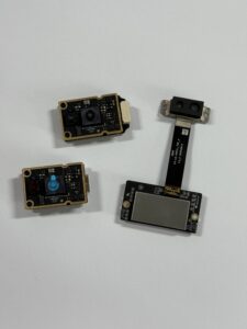
The DTOF Solid state LiDAR HM-LD1 is a compact solid-state LiDAR module based on SPAD dToF technology. It is designed to output real-time depth images and 3D point cloud data for robot perception, UAV altitude and obstacle sensing, autonomous navigation, inspection systems, smart cameras, and embedded vision development. With UART, UDP, and UVC interfaces, it can be integrated with PCs, Raspberry Pi platforms, flight controllers, and embedded Linux systems.
| Specification | DTOF Solid State LiDAR HM-LD1 |
|---|---|
| Dimension | 43.5mm × 30mm × 26.5mm |
| Ranging Capability | Indoor: 0.5–25m; Outdoor: 0.2–8m |
| Ranging Accuracy | ±3cm |
| FOV | 60° horizontal × 45° vertical |
| Weight | 28g |
| Resolution | 40 × 30 |
| Frame Rate | 10fps |
| Interface | UART / UDP / UVC |
| Operating Temperature | -20℃ to 60℃ |
| Power Consumption | 1.2W |
View Product Details & Pricing ➔
Compact Dimensions and 28g Lightweight Design
The HM-LD1 is designed for platforms where sensor size and mass directly affect product feasibility. Its compact housing makes it easier to integrate into autonomous mobile robots with limited sensor space, drones where payload affects flight distance, smart cameras, and embedded inspection devices. A 28g sensor can be mounted in more locations than a bulky mechanical scanning unit.
That lightweight design is especially useful during prototype work. Engineers can test different mounting locations, evaluate forward-facing or downward-facing layouts, and avoid major mechanical redesign while validating the sensor’s usefulness in the actual application.
Indoor and Outdoor Ranging Performance
The module supports indoor ranging from 0.5m to 25m and outdoor ranging from 0.2m to 8m. This makes it useful for indoor robotics, nighttime or controlled-light operation, and daytime outdoor scenarios where the working distance is within the outdoor range. For outdoor inspection, engineers should validate performance under realistic sunlight, surface reflectivity, and mounting conditions.
Look, outdoor ranging is always worth testing carefully. Sunlight, surface color, target angle, and vibration can all affect the returned signal. If the job involves drones, bridges, dams, roofs, or construction sites, test with real materials and real lighting before making final design decisions.
Depth Map and Point Cloud Output
The HM-LD1 provides real-time depth images and 3D point cloud data. This output is more informative than a single distance reading because it allows the system to understand spatial distribution across the sensor’s field of view. Robots can use this data for obstacle profiles, drones can use it for distance hold, and embedded applications can use it for scene awareness.
Depth maps are convenient for fast visualization and zone-based logic. Point clouds are useful when the software needs 3D spatial structure. Having both options gives developers flexibility during prototyping and deployment.
Brochure and Product Evaluation
For detailed project evaluation, engineers can review the DTOF SSL HM-LD1 Product Brochure. The brochure supports procurement and integration planning by helping teams confirm mechanical, electrical, and software compatibility before deployment.
A good evaluation should include bench testing, data visualization, interface validation, mounting trials, field testing, and full-system testing. The brochure is a starting point, but the final decision should be based on how the module behaves in the target machine.
Integration Interfaces and Development Platforms
LiDAR integration is not only about connecting power and reading data. The system must choose the right interface, data pipeline, operating system, development framework, and host controller. The HM-LD1 supports UART, UDP, and UVC, giving engineers flexibility across PC evaluation, embedded Linux development, flight controllers, and robotics platforms.
In the shop, integration problems usually show up where mechanical, electrical, and software assumptions meet. The sensor may power up fine, but the data format may not match the control loop. The interface may work on a PC, but not on the embedded target. The wiring may be simple on the bench, but noisy on a moving robot. Choosing the right interface early helps prevent those headaches.
Using UVC for Fast PC-Based Evaluation
UVC can simplify early testing because it allows the LiDAR module to behave more like a camera-class device in compatible workflows. This can be helpful when engineers want to visualize depth data quickly, confirm basic operation, or prototype software on a PC before moving to an embedded target.
For early development, speed matters. If the team can plug the sensor into a PC and quickly see depth output, they can validate basic function, compare mounting positions, and begin algorithm work before the full robot platform is ready.
Using UDP for Embedded Linux and Networked Systems
UDP is suitable for Linux-based robot computers, Raspberry Pi-style platforms, and networked embedded architectures. It can support data streaming to onboard computers that handle perception, logging, visualization, and decision-making. UDP may be a practical choice when the system already uses IP networking internally.
UDP can fit well in systems where the perception computer already handles networked sensors, cameras, logs, or telemetry. Engineers should still evaluate bandwidth, packet handling, latency, and recovery behavior if the data stream is used in time-sensitive control decisions.
Using UART for Flight Controllers and Embedded Control
UART is useful when the receiving controller is a microcontroller, flight controller, or embedded processor that expects serial communication. It can reduce system complexity where only structured distance or sensing data is needed for control behavior. UAV altitude sensing, simple obstacle warnings, and embedded zone detection are examples where UART may be relevant.
UART can be a clean choice for tightly embedded systems because it is simple, familiar, and widely supported. The tradeoff is bandwidth. If the application needs rich depth images or point clouds, engineers should confirm that the selected interface can carry the required data at the required update rate.
SDK Support for x86 Windows, x86 Linux, and ARM Linux
MRP offers SDKs for x86 Windows, x86 Linux, and ARM Linux. This is important because development teams often begin on a desktop environment, then migrate to an embedded ARM platform for deployment. SDK availability can reduce integration time, support testing, and help teams move from prototype to system implementation more efficiently. When ready to move toward procurement, teams can request pricing or start procurement.
SDK support matters because perception projects rarely stay on one computer forever. A team may start on Windows for visualization, move to Linux for robotics middleware, and finally deploy on an ARM-based embedded computer. The smoother that path is, the less time the team spends fighting drivers and data formats.
Industrial Application Scenarios for dToF LiDAR
dToF LiDAR is valuable because it connects technical specifications to real machine behavior. In industrial applications, the sensor is not selected for theoretical performance alone. It is selected because it helps a robot avoid an obstacle, helps a drone maintain distance, helps a camera detect presence, or helps an inspection system measure inaccessible structures.
Here’s where the rubber meets the floor. A sensor specification only matters if it improves the machine’s behavior. Range, FOV, resolution, frame rate, and interface all need to translate into better navigation, safer motion, more reliable detection, or cleaner inspection data.
Obstacle Avoidance for Autonomous Mobile Robots
Forward-facing depth sensing can help AMRs identify obstacles in front of the chassis. The robot can use depth distribution to detect people, pallets, walls, shelves, machinery, or unexpected objects. LiDAR data can complement other sensors and support local navigation decisions, especially in environments where visual recognition alone is not reliable.
For obstacle avoidance, the key is not only detecting that something exists. The robot needs enough distance information to decide what to do next. Should it slow down? Stop? Re-route? Ignore the object because it is outside the path? Depth data helps answer those questions.
UAV Altitude Hold and Terrain Following
For drones, LiDAR can support altitude hold, terrain following, and low-altitude stability. Unlike barometric pressure sensors, LiDAR can measure distance to the ground or a nearby surface directly. This can be useful for landing, hovering near structures, agricultural sensing, and inspection tasks where maintaining a controlled standoff distance is important.
Terrain following is a good example. If a drone flies over uneven ground, pressure altitude may not tell it how far it is from the surface below. A downward-facing LiDAR can provide direct surface distance, which helps the control system maintain a more consistent height above the terrain.
SLAM and Navigation Support
dToF LiDAR can support SLAM when its field of view, resolution, range, frame rate, and mounting position match the mapping algorithm’s requirements. In many compact systems, a depth module is used as part of a sensor-fusion stack rather than as the only mapping sensor. It may provide near-field obstacle perception while other sensors support broader localization and mapping.
For SLAM, consistency matters. The algorithm needs stable observations it can compare over time. A compact dToF module may be useful for local structure, near-field awareness, or supplementary depth, especially when combined with odometry, IMU data, cameras, or other LiDAR sensors.
Bridge, Expressway, Dam, and Infrastructure Inspection
The HM-LD1 product details highlight use cases where accurate ranging is helpful at distances up to 8m outdoors on a clear summer day under high illumination assumptions. This makes lidar tech useful for measuring distances to objects that are difficult for people to approach, such as bridges, expressways, and dams. In these scenarios, compact LiDAR can help a mobile platform maintain clearance and collect spatial data around critical structures.
Infrastructure inspection is a demanding application because access is difficult, surfaces are large, and conditions are rarely ideal. A compact dToF LiDAR module can help a drone or ground robot estimate distance to structural surfaces while the inspection payload collects images, thermal data, or other measurements.
Smart Camera Autofocus and User Presence Detection
Smart cameras can use depth data to improve autofocus, detect whether a user is present, or understand object distance. In human-machine interaction, knowing whether a person is physically present in a zone can be more useful than only detecting a face or silhouette in a 2D image.
Depth-aware autofocus can be faster and more reliable because the system has direct range information. Presence detection can also become more robust because the system can identify distance and occupancy, not just visual appearance.
Object Recognition, Volume Measurement, and Zone Monitoring
Depth sensing supports object recognition and volume measurement by adding spatial information to the scene. For example, a system can estimate whether a package occupies a monitored area, whether a container is full, or whether an object has crossed a defined zone. Security systems can use similar depth awareness for intrusion monitoring and occupied-zone detection.
In industrial automation, zone monitoring is often about simple but reliable decisions. Is something in the zone? How far away is it? Is it moving closer? Is it tall enough to matter? Depth data gives the software a more useful basis for those decisions than image data alone.
How to Choose the Right LiDAR Tech for Your System
Choosing the right lidar tech requires a structured evaluation process. Engineers should begin with the operating environment and system behavior, then map those requirements to sensor specifications. This approach reduces the risk of selecting a sensor that looks strong on paper but fails in the final application.
Look, the wrong way to choose a sensor is to sort by maximum range and buy the biggest number. The right way is to define the job, identify the constraints, test the sensor against those constraints, and confirm that the data can be used by the machine’s control and perception stack.
Step 1: Define the Operating Environment
⚙️ Decide whether the system operates indoors, outdoors, at night, in direct sunlight, near reflective surfaces, or around dark materials. Ambient light and target reflectivity can significantly affect real-world ranging performance.
For industrial machines, include the ugly details. Dust, glare, vibration, temperature, protective covers, sunlight angle, and target material can all change performance. A good test plan includes the conditions the sensor will actually face.
Step 2: Define Required Range and Minimum Detection Distance
⚙️ Maximum range matters, but minimum range is also critical. Close obstacles may create safety issues if the sensor cannot detect them. Compare the sensor’s range with stopping distance, mounting position, field of view, and control-loop timing.
Minimum range is often overlooked until the prototype is already moving. If the robot has a blind zone directly in front of it, the control system needs to account for that. Mounting position, bumper geometry, and stopping behavior should all be reviewed together.
Step 3: Match Field of View to Mounting Position
⚙️ Field of view should match the robot’s path, drone’s direction of travel, or camera’s monitored zone. Engineers should evaluate actual coverage after mounting, because housing geometry, tilt angle, and installation height change the useful sensing area.
A sensor with a good FOV on paper can still miss critical objects if it is mounted at the wrong angle. Test with real obstacles at different heights and distances. For robots, include pallets, feet, boxes, shelves, and floor transitions. For drones, include walls, ground surfaces, beams, and angled structures.
Step 4: Evaluate Resolution Against Object Size
⚙️ Resolution should be sufficient to detect the smallest relevant obstacle or target at the required distance. A 40 × 30 depth output may be useful for coarse shape and obstacle detection, but very small or thin objects may require additional sensing.
The important question is not whether the resolution sounds high. The important question is whether the object occupies enough measurement cells at the distance where the system must react. That depends on FOV, range, target size, and mounting geometry.
Step 5: Confirm Interface and SDK Compatibility
⚙️ Before selecting a module, confirm whether the host system supports UART, UDP, or UVC, and verify SDK availability for the target operating system. HM-LD1 SDK support for x86 Windows, x86 Linux, and ARM Linux can help teams move from prototype to deployment.
Interface and software support can save or burn weeks of engineering time. Confirm the data stream, operating system, SDK, cabling, power requirements, and development tools before locking the sensor into the mechanical design.
| Selection Question | Why It Matters | What to Verify |
|---|---|---|
| Will the system operate indoors, outdoors, or both? | Ambient light affects real-world ranging performance. | Compare indoor and outdoor range separately. |
| How fast does the robot or drone move? | Frame rate affects reaction time and perception freshness. | Match 10fps or higher requirements to platform speed. |
| How much space is available? | Compact platforms require small sensors. | Check 43.5mm × 30mm × 26.5mm mechanical fit. |
| What is the available power budget? | Battery systems are sensitive to power draw. | Confirm 1.2W consumption is acceptable. |
| Which controller or computer receives the data? | Interface compatibility reduces development risk. | Choose UART, UDP, or UVC based on architecture. |
| Do you need depth images, point clouds, or only distance? | Output format affects software design. | Confirm depth map and 3D point cloud support. |
✅ For compact robots, UAVs, and embedded perception projects, review the DTOF Solid state LiDAR HM-LD1 specifications or download the DTOF SSL HM-LD1 Product Brochure to evaluate mechanical, electrical, and software compatibility.
✅ A practical evaluation should include bench setup, SDK validation, live depth visualization, indoor range testing, outdoor sunlight testing, target-material testing, vibration checks, and final validation inside the robot or drone’s actual perception stack.
Technical FAQ About LiDAR Tech
How does LiDAR tech actually work, and why is dToF useful for robots?
Is solid-state LiDAR better than mechanical LiDAR for robotics and drones?
Is LiDAR worth using when GPS, signal, or camera-based navigation is unreliable?
What is the difference between a depth map and a point cloud?
What field of view is good for robot obstacle avoidance?
How important is LiDAR resolution?
Does outdoor sunlight affect dToF LiDAR performance?
What interface should I choose: UART, UDP, or UVC?
Can dToF LiDAR be used for SLAM?
Why does minimum range matter in robotics?
How should engineers test a LiDAR module before deployment?
📚 References & Further Reading
- Industry Standard: Time-of-flight measurement and industrial sensor technology
- Related Guide: How dToF LiDAR sees the 3D world and DTOF Solid state LiDAR HM-LD1






