LiDAR on Drones: How to Choose a Lightweight, Affordable Sensor for UAV Mapping, Obstacle Avoidance, and Inspection
Using LiDAR on drones is no longer something reserved for big survey aircraft, deep-pocketed enterprise mapping teams, or research programs with custom payload budgets. Here’s the deal: smaller UAV developers, inspection contractors, robotics labs, and industrial integrators now need compact sensors that can give a drone real distance awareness without wrecking the payload budget, draining the battery, or turning a simple prototype into a six-month integration project.
Look, the hard part is not finding a LiDAR sensor. The hard part is choosing the right LiDAR sensor for the job. A drone used for bridge inspection does not need the same hardware as a drone doing survey-grade forestry mapping. An indoor warehouse drone does not face the same sunlight problems as an outdoor inspection UAV. A university prototype may need easy SDK access and depth data, while a commercial mapping platform may need GNSS, IMU, calibration, and georeferenced point-cloud workflows.
This guide walks through how drone LiDAR works, what specifications actually matter, where compact solid-state dToF modules fit, and when a lightweight sensor is the smart choice for UAV mapping prototypes, obstacle avoidance, altitude sensing, terrain following, and industrial inspection. We will also look at the DTOF Solid State LiDAR HM-LD1, a 28g solid-state LiDAR module with 60° × 45° FOV, ±3cm accuracy, 10fps depth output, and UART / UDP / UVC interfaces.
View Product Details & Pricing ➔
Table of Contents
- 👉 What Is LiDAR on Drones?
- 👉 How Drone LiDAR Works
- 👉 Main Use Cases: Mapping, Obstacle Avoidance, and Inspection
- 👉 Types of LiDAR Sensors for UAVs
- 👉 Key Specifications to Compare Before Buying LiDAR on Drones
- 👉 Why Lightweight and Affordable LiDAR Matters for Small UAVs
- 👉 Product Spotlight: DTOF Solid State LiDAR HM-LD1
- 👉 Drone LiDAR Integration Workflow
- 👉 Mapping LiDAR vs Obstacle-Avoidance LiDAR
- 👉 Indoor, Outdoor, and Harsh-Environment Performance
- 👉 Software, SDK, Point Clouds, and Depth Maps
- 👉 Drone LiDAR Buyer Checklist
- 👉 FAQ: LiDAR on Drones
What Is LiDAR on Drones?
LiDAR stands for Light Detection and Ranging. In a drone application, it means mounting a laser-based ranging sensor, scanning module, or 3D perception device on a UAV so the aircraft can measure distance to the ground, nearby structures, obstacles, terrain, racks, machinery, roofs, bridge members, or other objects in its operating area.
In the shop, I like to explain LiDAR this way: a camera tells you what something looks like, while LiDAR tells you how far away it is. A standard RGB camera gives color, texture, contrast, and object appearance. That is useful, but it does not directly provide distance unless you add stereo vision, motion estimation, AI depth prediction, or another sensing method. LiDAR is built around distance measurement from the start.
That direct range information is valuable for altitude hold, terrain following, landing assistance, obstacle detection, inspection stand-off control, local mapping, robot navigation, and autonomous flight development. A drone can use LiDAR data to know whether a wall is two meters ahead, whether a roof is five meters below, or whether a structure is getting too close during inspection.
Still, not every UAV LiDAR system is built for the same mission. A survey-grade airborne mapping payload may include a high-end scanner, precision GNSS, IMU, time synchronization, calibrated mounting, and geospatial post-processing software. Those systems are excellent for forestry, mining, construction, corridor mapping, and topographic surveys, but they can be expensive, heavy, and more complex than many small-drone teams need.
Compact solid-state dToF LiDAR modules live in a different category. They are usually smaller, lighter, lower power, and easier to integrate into embedded systems. They are not meant to replace a full professional survey payload. Instead, they help a drone understand local space in real time. That makes them useful for short-range obstacle avoidance, indoor navigation, low-altitude sensing, inspection development, robotics education, and prototype autonomy.
For readers working on UAV localization, sensor fusion, and autonomous navigation design, see our related guide on observability in robot state estimation. Observability matters when LiDAR data is combined with IMU, camera, GNSS, barometer, or other measurements in a navigation stack.
How Drone LiDAR Works
Drone LiDAR works by sending light toward a target and measuring the returned signal. Depending on the sensor architecture, it may output a single distance value, a 2D scan, a depth image, or a 3D point cloud. For UAV work, the practical concepts are time-of-flight measurement, field of view, resolution, frame rate, reflectivity, outdoor light tolerance, and how the sensor presents depth data to the software.
Time-of-Flight Distance Measurement
Time-of-flight LiDAR measures distance by calculating how long it takes for emitted light to travel from the sensor to an object and return. In direct time-of-flight, or dToF, the system measures the photon return timing directly. The basic relationship is: Distance = (Speed of Light × Time of Flight) / 2. The division by two is required because the light travels to the target and then back to the receiver.
On a drone, this measurement happens rapidly and repeatedly. A downward-facing LiDAR can estimate altitude above a floor, field, roof, or road surface. A forward-facing unit can measure distance to walls, trees, poles, machinery, shelves, or bridge structures. A wider-FOV module can provide a small depth image, which lets the software see where obstacles are inside the sensing cone rather than relying on one narrow beam.
Solid-State LiDAR and SPAD dToF
Solid-state LiDAR refers to designs that avoid large spinning mechanical assemblies. For UAVs, that matters. Moving assemblies can add weight, volume, mechanical wear, vibration sensitivity, and mounting headaches. A compact solid-state module is often easier to install on a small airframe, especially when the drone already has tight limits on payload mass and battery capacity.
The DTOF Solid State LiDAR HM-LD1 is based on SPAD dToF technology. SPAD stands for Single Photon Avalanche Diode, a detector technology used for photon-level timing. In practical engineering terms, SPAD dToF enables compact 3D sensing, real-time depth images, and point-cloud output in a package that makes sense for embedded platforms. For small drones, the advantages are low weight, low power draw, flexible mounting, and easier development.
For readers comparing LiDAR architectures and industrial applications, companies such as Blickfeld provide useful context on LiDAR design approaches and market use cases. Just remember: do not buy based on one flashy number. Buy based on the mission.
Depth Map vs Point Cloud
A depth map is a 2D image where each pixel stores distance instead of color. For example, the center of the image may show a wall at three meters while the lower-left region shows an object at one meter. That format is convenient for obstacle detection because software can divide the image into zones and look for the nearest valid return.
A point cloud is a 3D representation of measured points, usually expressed as X, Y, and Z coordinates. Point clouds are useful for visualization, mapping prototypes, inspection workflows, SLAM, and surface reconstruction. Many UAV systems use depth maps for fast obstacle logic and point clouds for higher-level perception or analysis.
Field of View, Resolution, and Frame Rate
Field of view describes how wide and tall the sensing area is. The HM-LD1 provides a 60° horizontal × 45° vertical field of view. That gives a practical sensing cone for forward, downward, or angled mounting. Resolution describes how many distance samples are available in the depth frame. The HM-LD1 provides 40 × 30 resolution at 10fps.
Those numbers position the sensor as a short-range 3D perception module, not a dense airborne survey scanner. That is not a knock against it. For obstacle avoidance, terrain following, low-altitude sensing, and embedded autonomy development, a lightweight depth sensor can be more useful than a heavy mapping payload that the airframe cannot realistically carry.
Main Use Cases: Mapping, Obstacle Avoidance, and Inspection
The phrase “LiDAR on drones” covers several different jobs. Some buyers want professional mapping data. Some want a drone to stop before it hits a wall. Others want safer inspection stand-off control near bridges, tanks, roofs, towers, dams, or machinery. The use case comes first. The sensor choice comes second.
UAV Mapping and 3D Reconstruction
Drone LiDAR mapping usually means collecting distance measurements over an area to create terrain models, surface models, structural geometry, or digital twins. Professional geospatial mapping normally requires more than a bare LiDAR module. It may require precision GNSS, IMU data, time synchronization, calibrated sensor mounting, flight planning, and post-processing software.
Compact LiDAR modules still have a place in mapping development. They can support indoor mapping prototypes, short-range scene reconstruction, SLAM experiments, occupancy-grid testing, robotics education, and early algorithm validation. A lab or startup may use a compact dToF LiDAR to prove its perception workflow before investing in a larger payload.
Obstacle Avoidance
Obstacle avoidance is one of the strongest use cases for compact LiDAR on drones. A UAV can use distance data to detect walls, racks, poles, people, equipment, trees, and structural elements in the flight path. Unlike a camera-only approach, LiDAR gives direct range data that can be converted into warning zones, stop commands, or route adjustments.
For obstacle avoidance, the key questions are simple but important. How fast is the drone moving? How quickly can it stop? What field of view is required? How much latency is acceptable? What surfaces must it detect? A slow indoor inspection drone can work with shorter sensing distances than a fast outdoor platform. The HM-LD1’s 60° × 45° field of view and 10fps output make it suitable for short-range perception, development work, and controlled inspection scenarios.
Altitude Hold and Terrain Following
A downward-facing LiDAR can measure distance from the drone to the ground, floor, roof, or inspected surface. That can improve low-altitude stability where barometers, GPS, or vision-only methods may struggle. Applications include indoor UAVs, agricultural drones, inspection platforms, landing assistance, and terrain-following prototypes.
The HM-LD1 supports indoor ranging from 0.5–25m and outdoor ranging from 0.2–8m. Product descriptions also reference indoor or nighttime sensing up to 25m and outdoor daytime use up to 8m. That range profile makes sense for low-altitude sensing, short-range inspection, and embedded drone perception development.
Industrial Inspection
Industrial inspection drones operate around bridges, expressways, dams, storage tanks, warehouses, power facilities, construction sites, and other structures where access can be dangerous or expensive. LiDAR helps the drone estimate distance to the inspected surface and maintain a more consistent stand-off distance.
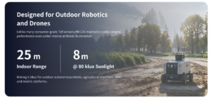
The HM-LD1 product description notes accurate outdoor measurement at 8 meters on a clear summer day, assuming approximately 80,000 lux. That detail matters because bright sunlight is a real challenge for compact ToF sensors. For inspection work around infrastructure, documented short-range daylight performance is worth paying attention to.
For teams evaluating advanced UAV inspection payloads, our article on why the tri-spectral gimbal pod is a game changer gives additional context on multi-sensor inspection. In many industrial UAV jobs, the best solution combines sensors instead of expecting one device to do everything.
Types of LiDAR Sensors for UAVs
Before buying a drone LiDAR sensor, it helps to separate the major categories. A survey-grade scanner, compact solid-state dToF module, 2D scanning LiDAR, and depth camera may all support perception, but they are not interchangeable.
Survey-Grade Mapping LiDAR
Survey-grade mapping LiDAR systems are designed for professional data products. They typically offer longer range, higher point density, precision timing, and integration with GNSS/INS systems. These payloads are common in terrain mapping, forestry, mining, construction surveying, and corridor inspection. They are powerful, but they are often larger, heavier, more power-hungry, and more expensive.
If the job is certified geospatial mapping, this kind of payload may be necessary. If the job is to avoid nearby obstacles, maintain altitude, or prototype local perception, it may be overkill.
Solid-State dToF LiDAR Modules
Solid-state dToF LiDAR modules are compact, lightweight, low-power sensors that often output depth maps and point clouds. They are well suited for small drones, robot navigation, obstacle avoidance, altitude sensing, education, and embedded autonomy development.
The DTOF Solid State LiDAR HM-LD1 is a strong example of this category. It weighs 28g, consumes 1.2W, provides a 60° × 45° field of view, outputs 40 × 30 depth data at 10fps, and supports UART, UDP, and UVC interfaces. Those are practical specifications for teams that need local 3D perception instead of a heavy airborne mapping system.
2D Scanning LiDAR
2D scanning LiDAR sensors measure distance across a single plane. They are popular on ground robots because a horizontal scan can detect walls, furniture, people, and other obstacles. On drones, a single 2D plane can be limiting unless the sensor is carefully mounted or mechanically swept. UAVs move in three dimensions, so 3D depth output is often more useful for obstacle awareness.
Depth Cameras and ToF Cameras
Some projects use depth cameras instead of LiDAR modules. Depth cameras can be effective indoors and in robotics workflows that need camera-style data. The better choice depends on range, sunlight tolerance, resolution, field of view, data format, and integration requirements.
If your project needs camera-style depth perception, compare options such as the 3D Depth Camera P100R. In real engineering work, LiDAR and depth cameras can both be valid depending on the operating environment.
Key Specifications to Compare Before Buying LiDAR on Drones
Choosing LiDAR for drones is a trade-off exercise. The right sensor has to fit the airframe, payload budget, power system, software stack, safety margin, and environment. One impressive specification does not help if the sensor is too heavy, too hard to mount, or unreliable in the actual lighting conditions.
Weight and Payload Budget
Drone flight time is sensitive to payload weight. A few hundred grams may be acceptable on a large industrial multirotor, but it can be a deal-breaker on a small UAV. Remember that the final payload includes the sensor, mounting bracket, cables, enclosure, fasteners, companion computer, power regulator, and vibration isolation.
The HM-LD1 weighs 28g, which makes it practical for compact drone integration. Low weight preserves endurance and gives engineers more freedom in sensor placement.
Size and Mounting Constraints
The HM-LD1 product table lists dimensions of 43.5mm × 30mm × 26.5mm. The product description also references compact housing dimensions of 43.5mm × 43.5mm × 28.5mm. In production work, always confirm the latest mechanical drawing before designing a mount.
Mounting location should avoid propeller obstruction, landing gear shadows, cable strain, and body occlusion. A forward-facing LiDAR needs a clean view ahead. A downward-facing LiDAR should not be blocked by landing legs. For inspection, angled mounting may provide better coverage of the structure while still supporting approach control.
Range
The HM-LD1 lists Indoor: 0.5–25m and Outdoor: 0.2–8m. Outdoor range is shorter because sunlight creates optical background noise. Target reflectivity, surface angle, atmosphere, laser power, and receiver sensitivity also affect measurement quality.
For obstacle avoidance, required range depends on speed and stopping distance. For altitude hold, the required range may be much shorter. For professional mapping, longer range and higher point density may be critical.
Accuracy
The HM-LD1 specifies ±3cm ranging accuracy. That is useful for altitude estimation, obstacle thresholds, inspection stand-off distance, and landing assistance. But ranging accuracy is not the same as survey-grade absolute georeferencing accuracy. Professional mapping accuracy depends on pose estimation, calibration, synchronization, and post-processing.
Field of View
The HM-LD1 provides a 60° horizontal × 45° vertical field of view. A wider field of view improves local awareness because the drone sees more of the scene at once. Mounting angle matters: forward for obstacle detection, downward for altitude, and angled forward/down for inspection and landing approaches.
Resolution and Frame Rate
The HM-LD1 outputs 40 × 30 resolution at 10fps. For obstacle avoidance, extremely dense imagery is not always required. Stable near-field depth, predictable latency, and solid filtering often matter more. For detailed reconstruction or survey mapping, higher point density may be required.
Interface and Platform Compatibility
The HM-LD1 supports UART / UDP / UVC. UART can be practical for lightweight embedded integration. UDP works well for companion-computer workflows. UVC can simplify PC or embedded Linux testing when the device behaves like a depth-streaming sensor.
MRP offers SDKs for x86 Windows, x86 Linux, and ARM Linux. That helps teams prototype on a PC and then migrate to Raspberry Pi, Jetson-style embedded computers, or other ARM Linux platforms.
Power Consumption and Thermal Design
The HM-LD1 consumes 1.2W. Low power reduces battery impact, heat load, and regulator stress. Designers should still check voltage stability, connector retention, cable voltage drop, electromagnetic interference, and thermal behavior inside the final drone enclosure.
Operating Temperature
The HM-LD1 operating temperature is -20°C to 60°C. That supports many indoor and outdoor industrial environments, but the whole UAV system must be tested. Batteries, regulators, companion computers, and enclosures all have their own limits.
Why Lightweight and Affordable LiDAR Matters for Small UAVs
Many teams start by searching for affordable drone LiDAR, cheap LiDAR for drones, or drone LiDAR under a limited budget. Usually, what they really need is not a professional survey payload. They need a practical sensor that enables learning, prototyping, obstacle detection, or short-range perception without overwhelming the airframe.
Survey-grade systems are powerful, but they can be excessive for early development. A university lab, startup, robotics team, or industrial prototype group may not need dense geospatial deliverables on day one. They may need to answer basic engineering questions first: Where should the sensor go? Can the drone identify a wall? Is the depth stream stable? Can the data feed an occupancy grid? Can the UAV maintain stand-off distance from a structure?
A compact dToF module is often the right starting point. It lets teams prototype perception behavior, validate sensor placement, test filtering, and build basic autonomy workflows. If the mission later requires certified geospatial mapping, the team can scale to a higher-end payload with GNSS/INS and mapping software.
Weight matters just as much as cost. A small UAV can lose meaningful flight time when carrying a heavy payload. A 28g module is much easier to integrate than a large scanner, and low power consumption simplifies the electrical design.
Product Spotlight: DTOF Solid State LiDAR HM-LD1
The DTOF Solid State LiDAR HM-LD1 is a compact SPAD dToF LiDAR module designed for embedded 3D sensing, drone obstacle avoidance, robot navigation, distance detection, and UAV inspection development. With a lightweight 28g body, 1.2W power consumption, and multiple interfaces including UART, UDP, and UVC, it is built for teams that need practical short-range perception without the size and cost burden of survey-grade LiDAR payloads.
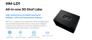
The module delivers real-time depth images and 3D point-cloud data for environmental perception. It supports indoor or nighttime ranging up to 25m and outdoor daytime ranging up to 8m. For drone builders, the most relevant applications are short-range obstacle detection, low-altitude sensing, inspection stand-off measurement, terrain-following development, and embedded 3D perception.
| Specification | DTOF Solid State LiDAR HM-LD1 | Why It Matters for Drones |
|---|---|---|
| Technology | Solid-state SPAD dToF LiDAR | Compact 3D sensing without large rotating mechanisms; suitable for UAV integration. |
| Dimensions | 43.5mm × 30mm × 26.5mm | Small mechanical footprint for compact drone payload bays or custom mounts. |
| Weight | 28g | Low payload weight helps preserve flight time and supports small UAV platforms. |
| Ranging Capability | Indoor: 0.5–25m; Outdoor: 0.2–8m | Supports indoor navigation, low-altitude sensing, and short-range outdoor inspection. |
| Ranging Accuracy | ±3cm | Useful for altitude sensing, obstacle distance estimation, and stand-off inspection. |
| Field of View | 60° horizontal × 45° vertical | Provides a practical sensing cone for forward, downward, or angled mounting. |
| Resolution | 40 × 30 | Generates depth data for obstacle detection and local 3D perception. |
| Frame Rate | 10fps | Supports real-time depth updates for slow to moderate UAV perception tasks. |
| Interfaces | UART / UDP / UVC | Flexible integration with flight controllers, PCs, Raspberry Pi, and embedded platforms. |
| Operating Temperature | -20°C to 60°C | Suitable for many indoor and outdoor industrial drone environments. |
| Power Consumption | 1.2W | Low power demand helps reduce battery impact and thermal load. |
| Supported Development Platforms | x86 Windows, x86 Linux, ARM Linux SDKs | Enables rapid prototyping on PCs and embedded systems. |
View product details: DTOF Solid State LiDAR HM-LD1
Download the product brochure: DTOF SSL HM-LD1 Product Brochure
View Product Details & Pricing ➔
Drone LiDAR Integration Workflow
Integrating LiDAR into a UAV is not just a matter of bolting on a sensor. A reliable system needs mission definition, mechanical mounting, power planning, data connection, coordinate calibration, software filtering, and disciplined flight testing. Skip those steps and you will spend more time chasing strange behavior than collecting useful data.
Step 1 — Define the Mission
Start by defining what the drone must accomplish. Is it mapping, inspecting, avoiding obstacles, following terrain, supporting landing, or collecting research data? Is the flight environment indoor, outdoor, or both? Does the software need point clouds, depth maps, or simple distance thresholds?
These answers determine the sensor category. A compact dToF module is a good fit for short-range perception and development. A survey payload is better for geospatial mapping. A depth camera may be better for close-range visual robotics.
Step 2 — Choose Mounting Direction
Mounting direction should match the job. A downward-facing sensor supports altitude hold, terrain following, and landing assistance. A forward-facing sensor supports obstacle avoidance. An angled forward/down sensor can be useful for inspection, landing approach, and near-surface navigation.
The mount should provide a clear field of view and control vibration. The LiDAR should not be blocked by landing gear, payload rails, propeller guards, cables, or the drone body.
Step 3 — Power and Data Connection
Power design should account for sensor consumption, regulator capacity, voltage stability, connector retention, and electromagnetic interference. The HM-LD1’s 1.2W draw is modest, but the whole payload may include a companion computer, radio, camera, and other electronics.
Interface selection depends on the software architecture. UART is practical for lightweight embedded data. UDP works well for networked companion-computer workflows. UVC may simplify camera-like streaming to a PC or embedded Linux platform.
Step 4 — Calibrate Coordinate Frames
The system must understand the relationship between the LiDAR frame, drone body frame, IMU frame, camera frame, and map frame. This is extrinsic calibration. If the sensor is mounted at an angle and the software does not know that angle, the drone may misinterpret walls, floors, and obstacles.
Step 5 — Process Depth Data
Depth processing may include converting depth images into point clouds, filtering invalid pixels, applying confidence thresholds, detecting nearest obstacles, removing ground planes, segmenting regions, or generating local occupancy grids. For simple altitude sensing, a filtered distance estimate may be enough. For obstacle avoidance, the software may divide the field of view into zones and evaluate the nearest valid object in each zone.
Step 6 — Flight Testing
Testing should begin on the bench with known targets and controlled distances. Then preview depth data on a PC, verify measurements, test different surfaces, and confirm the field of view. After mounting the sensor, check vibration, cable strain, power stability, and data latency.
Flight testing should progress gradually: static testing, tethered testing, low-speed manual flight, supervised autonomous behavior, and outdoor validation. For outdoor operation, test bright sunlight, cloudy conditions, shadows, dark surfaces, reflective materials, and angled targets before trusting the data for autonomous decisions.
Mapping LiDAR vs Obstacle-Avoidance LiDAR
One common mistake is assuming all drone LiDAR systems are interchangeable. Mapping LiDAR and obstacle-avoidance LiDAR use similar distance-sensing principles, but their system requirements are different. Mapping is about accurate 3D models. Obstacle avoidance is about detecting nearby hazards fast enough to react.
| Category | Mapping LiDAR | Obstacle-Avoidance LiDAR |
|---|---|---|
| Primary Goal | Create accurate 3D models or terrain data | Detect nearby obstacles in real time |
| Typical Range | Longer range | Short to medium range |
| Point Density | High | Moderate or application-dependent |
| Payload Size | Often larger and heavier | Can be compact and lightweight |
| Cost | High | Often more affordable |
| Best For | Surveying, forestry, construction, geospatial mapping | Drone navigation, inspection, terrain following, robotics development |
A compact LiDAR such as the HM-LD1 should be evaluated as a short-range 3D perception and obstacle-awareness module, not as a full replacement for a geospatial mapping payload. If the drone needs local awareness, a compact module may be ideal. If it needs certified mapping deliverables, a dedicated survey system is usually required.
Indoor, Outdoor, and Harsh-Environment Performance
LiDAR performance changes with the environment. Indoor lighting, outdoor sunlight, target reflectivity, temperature, vibration, and surface geometry all affect measurement reliability. Drones make this harder because the sensor is moving, vibrating, tilting, and often operating close to complex surfaces.
Indoor Performance
Indoor environments usually provide better conditions for compact ToF LiDAR because sunlight interference is limited. Warehouses, laboratories, tunnels, inspection corridors, production floors, and robotics test areas are common use cases. The HM-LD1 specifies 0.5–25m indoor range, which supports indoor navigation, obstacle detection, depth visualization, and short-range mapping prototypes.
Outdoor Daylight Performance
Outdoor sunlight creates background optical noise. That is why compact LiDAR modules often list separate indoor and outdoor ranges. The HM-LD1 supports 0.2–8m outdoor range, and the product description notes measurement at 8m on a clear summer day at approximately 80,000 lux. For short-range inspection around structures, that is a useful operating reference.
Surface Reflectivity
Surface material matters. Dark materials can absorb light. Glossy surfaces can reflect light away from the receiver. Glass may transmit or reflect unpredictably. Water can produce unstable returns. Metallic surfaces may create difficult reflections depending on angle. For UAV safety, test the real surfaces expected in the mission area.
Temperature and Industrial Reliability
The HM-LD1 operating temperature is -20°C to 60°C. That range supports many industrial UAV environments, but the complete drone system must be tested as an assembly. Enclosures can trap heat. Batteries can sag in cold weather. Companion computers can throttle in high temperatures.
Additional sensor manufacturers such as domisensor can be referenced when comparing industrial sensing options across different environments. The best sensor choice depends on mission constraints, data requirements, environmental exposure, and integration complexity.
Software, SDK, Point Clouds, and Depth Maps
Software support can decide whether a drone LiDAR project moves quickly or turns into a long integration slog. Hardware specifications matter, but developers also need SDKs, sample tools, documentation, supported operating systems, and a clear route from raw depth output to useful flight behavior.
SDK Support
MRP offers SDKs for x86 Windows, x86 Linux, and ARM Linux. That matters because many teams begin on a Windows or Linux PC, then deploy to an ARM Linux companion computer. Raspberry Pi and Jetson-style platforms are common in UAV prototyping because they can process sensor data before passing simplified commands or status information to the flight controller.
Data Output
The HM-LD1 delivers real-time depth images and 3D point-cloud data. A depth image is convenient for zone-based obstacle detection, while a point cloud is useful for visualization, mapping prototypes, and 3D perception. Depending on the software stack, teams may filter the data, transform it into the drone body frame, publish it into middleware, or convert it into control constraints.
ROS and Robotics Middleware
Teams commonly integrate depth sensors into ROS-based workflows using SDK streams, custom drivers, or middleware adapters. The usual workflow is to read sensor frames, timestamp them, apply calibration, convert depth to point cloud if needed, and publish the data for mapping, navigation, visualization, or control modules.
Flight Controller Integration
Direct flight-controller integration may use simplified distance data for altitude hold or proximity sensing. Companion computers are better for depth maps and point clouds because they provide more processing power. In advanced drone applications, the companion computer detects obstacles or safe zones, then sends simplified commands to the flight controller.
Safety-critical obstacle avoidance requires conservative thresholds, timeout handling, failsafe behavior, and plenty of testing. If LiDAR data becomes invalid, delayed, or inconsistent, the drone must behave safely.
Drone LiDAR Buyer Checklist
Before purchasing LiDAR for a drone, use a structured checklist. The goal is not to buy the most expensive sensor. The goal is to buy the right sensor for the job.
- ✅ Define whether the drone needs mapping, obstacle avoidance, altitude sensing, inspection support, or development data.
- ✅ Check payload weight, including the sensor, mount, cable, compute board, enclosure, and fasteners.
- ✅ Compare indoor and outdoor range separately instead of relying on one maximum number.
- ✅ Verify ranging accuracy and confirm that it supports your safety margin.
- ✅ Match field of view to the mounting direction and mission type.
- ✅ Confirm resolution and frame rate against the drone’s expected flight speed.
- ✅ Check interface compatibility: UART, UDP, UVC, USB, Ethernet, or serial.
- ✅ Confirm SDK support for your development platform.
- ✅ Validate power consumption against the drone battery and regulator design.
- ✅ Test real lighting, reflectivity, vibration, temperature, and target-angle conditions before flight.
For lightweight UAV perception and short-range 3D sensing, explore the DTOF Solid State LiDAR HM-LD1. It is especially relevant for obstacle avoidance, altitude sensing, terrain-following prototypes, inspection support, and embedded 3D perception.
View Product Details & Pricing ➔
FAQ: LiDAR on Drones
Is there any LiDAR suitable for small drones?
Can beginners use LiDAR on drones for mapping or inspection?
Is there a drone LiDAR option under $1k or on a budget?
What is the difference between drone LiDAR mapping and drone obstacle avoidance?
How much range does a drone LiDAR need?
Can LiDAR work outdoors in sunlight?
Is LiDAR better than a camera for drone obstacle avoidance?
Can a lightweight LiDAR module replace a survey-grade drone LiDAR system?
What interfaces are best for connecting LiDAR to a drone?
What should I test before flying a drone with LiDAR?
For teams ready to evaluate lightweight LiDAR on drones for short-range 3D perception, obstacle avoidance, altitude sensing, or inspection development, the DTOF Solid State LiDAR HM-LD1 provides a compact solid-state option with practical UAV-oriented specifications.
View Product Details & Pricing ➔
📚 References & Further Reading
- Industry Standard: Blickfeld | domisensor
- Related Guide: Observability in Robot State Estimation | Why the Tri-Spectral Gimbal Pod Is a Game Changer | 3D Depth Camera P100R | DTOF Solid State LiDAR HM-LD1