

What is LiDAR technology? Here’s the deal: LiDAR, short for Light Detection and Ranging, is a 3D sensing technology that uses laser light to measure distance, map spaces, and generate usable depth data. A regular camera gives you a flat image. LiDAR gives you range. It tells a machine how far away surfaces and objects are, which is exactly the kind of information robots, drones, inspection tools, and automation systems need when they have to move through the real world instead of just look at it.
For engineers, integrators, and product teams, LiDAR matters because it turns physical surroundings into distance values, depth maps, and 3D point clouds that software can actually use. That data can support obstacle avoidance, SLAM mapping, altitude hold, terrain following, volume measurement, presence detection, and machine navigation. This guide walks through how LiDAR works, the major types of LiDAR sensors, where it is used, how it compares with cameras and radar, and how compact solid-state dToF modules such as the DTOF Solid State LiDAR HM-LD1 can support robotics, drones, AR, and industrial automation projects.
Table of Contents
- 👉 What Is LiDAR Technology?
- 👉 How Does LiDAR Work?
- 👉 Depth Maps, Point Clouds, and 3D LiDAR Data
- 👉 Types of LiDAR Technology
- 👉 Key Components of a LiDAR System
- 👉 LiDAR Applications by Industry
- 👉 LiDAR vs Camera vs Radar
- 👉 How to Choose an Industrial LiDAR Module
- 👉 DTOF Solid State LiDAR HM-LD1 Specs and Product Fit
- 👉 Integration Workflow for Developers
- 👉 Limitations and Engineering Considerations
- 👉 LiDAR Technology FAQ
What Is LiDAR Technology?
LiDAR technology is a way to measure distance and spatial structure by sending out light and studying the reflected signal that comes back from surrounding objects. In plain shop-floor language, LiDAR is laser-based distance measurement. In more technical terms, it is an optical sensing method that can use time-of-flight, phase shift, or other signal measurement techniques to convert light-return data into distance, depth, and 3D geometry.
The biggest difference between LiDAR and a conventional camera is simple: LiDAR measures distance directly. A camera records color, texture, edges, and image features. Those signals are useful, especially for recognition, but they do not automatically tell a robot how far away a pallet, wall, shelf, or person is. LiDAR fills that gap by giving machines spatial awareness. It helps a system understand not just what might be in front of it, but where that object sits in physical space.
In industrial systems, LiDAR often acts as the perception layer for robots, drones, smart cameras, inspection equipment, security systems, and automation devices. A mobile robot can use LiDAR to detect walls, pallets, people, charging stations, or temporary obstacles left in an aisle. A drone can use LiDAR for altitude hold, terrain following, landing assistance, and obstacle detection. An inspection platform can use LiDAR to measure the geometry of structures that may be difficult, dangerous, or expensive for people to approach.
LiDAR became important because automation systems are being asked to work in messier, less predictable environments. In the shop, nothing stays perfect for long. Pallets move, boxes shift, dust builds up, lighting changes, people walk through work cells, and equipment vibrates. Autonomous mobile robots, UAVs, AR devices, smart security systems, and embedded vision products all benefit from compact sensors that provide direct depth data. As solid-state LiDAR modules have become smaller and easier to integrate, engineers can now add 3D sensing to products where older mechanical scanning sensors would have been too large, heavy, fragile, or complicated.
For embedded projects that need compact 3D depth sensing, modules such as the DTOF Solid State LiDAR HM-LD1 are designed for robotics, drones, and industrial perception applications where depth maps and point cloud data are more useful than a single distance reading. That distinction matters. A single-point rangefinder can tell you one distance. A compact 3D LiDAR module can give the controller a broader view of the scene, which helps with decisions like whether an obstacle is centered, offset, moving, or occupying a defined safety zone.
How Does LiDAR Work?
LiDAR works by emitting light, receiving reflected light, and calculating distance from the measured signal. Different products use different architectures, but most LiDAR systems follow a practical sequence: send laser light into the scene, detect the light that reflects back, measure timing or phase behavior, and process that information into distance data the rest of the system can use.
Step 1 — Emit Laser Light
⚙️ The first step is emission. A LiDAR transmitter sends out laser pulses or modulated light toward the environment. In compact depth sensors, that emission may cover a defined field of view so the module can capture information from many points in the scene. The laser source, optical design, pulse timing, power control, and eye-safety design all influence range, accuracy, signal quality, and integration limits.
Look, this is where engineers need to pay attention to more than just the headline range number. Two sensors may both claim useful indoor range, but their behavior can be very different when you mount them behind a protective window, run them near a vibrating motor, or point them at dark rubber, glossy plastic, or uneven concrete. The emitter is only one piece of the chain, but it sets the foundation for everything that follows.
Step 2 — Light Reflects from Objects
⚙️ After leaving the sensor, the light travels through air, reaches a surface, and reflects back toward the receiver. Different materials reflect light differently. White walls, concrete, vegetation, matte plastic, dark fabric, glass, water, and shiny metal can produce very different return signals. This is why industrial LiDAR evaluation should include real targets from the intended operating environment, not just clean laboratory surfaces.
In the shop, a sensor that looks great on a white test board may behave differently around black conveyor belts, oily metal parts, reflective packaging, or dusty safety guarding. That does not mean the sensor is bad. It means optical sensing follows real physics. Good deployment starts with understanding the surfaces, angles, lighting, and distances the module will actually see.
Step 3 — Sensor Measures Return Time
⚙️ In direct time-of-flight LiDAR, often written as dToF LiDAR, the system measures the time between light emission and light return. Because the speed of light is known, the sensor can calculate distance from the elapsed travel time. The measured path is a round trip, so the system divides that travel distance by two to determine the one-way distance from the sensor to the object.
This timing has to be extremely precise. Small differences in return time correspond to meaningful differences in distance. That is why detector sensitivity, timing electronics, calibration, and signal processing are central to LiDAR performance. A compact module may look simple from the outside, but internally it depends on tightly coordinated optics, electronics, firmware, and filtering.
Step 4 — Processor Converts Signals into Distance Data
⚙️ A LiDAR module does not usually hand the host processor a pile of raw light readings and call it a day. It typically processes the returned signal into usable outputs such as distance values, depth maps, 3D point clouds, confidence values, frame-based spatial measurements, or software-ready data streams. In embedded systems, that onboard processing can reduce development burden because the host controller does not need to build the entire measurement pipeline from scratch.
LiDAR accuracy depends on timing precision, sensor calibration, optical alignment, target reflectivity, ambient light, temperature, range, field of view, and internal filtering. For example, the DTOF Solid State LiDAR HM-LD1 lists a ranging accuracy of ±3 cm, showing how compact industrial dToF modules can support centimeter-level distance measurement for practical perception tasks such as obstacle detection, altitude control, and embedded depth sensing.
For broader industry context on solid-state LiDAR development and sensing trends, companies such as SOS LAB provide useful background on LiDAR architectures and applications.
Depth Maps, Point Clouds, and 3D LiDAR Data
One reason LiDAR technology is useful for robotics and automation is that it can output data in forms machines can act on. Depending on the sensor and software stack, LiDAR data may appear as individual distance measurements, depth images, point clouds, confidence maps, or higher-level object and zone information.
Distance Measurements
The simplest LiDAR output is a distance value. A single-point rangefinder may report one distance along one direction. A 3D LiDAR module expands that idea by collecting distance values across many measurement points. Each point or pixel represents how far a surface is from the sensor. These measurements can be used for triggering actions, measuring clearances, detecting obstacles, or controlling distance from a target.
✅ Distance data is especially useful when the control problem is direct and bounded. For example, a drone may need to hold height above ground, a camera may need subject distance for autofocus, or a robot may need to slow down when an object enters a near zone. In those cases, the value of LiDAR is not that it creates a beautiful 3D model. The value is that it gives the controller a trustworthy measurement at the right time.
Depth Maps
A depth map is a two-dimensional image in which each pixel stores distance information instead of color. This makes depth maps useful for obstacle detection, human presence detection, smart cameras, AR placement, zone monitoring, autofocus, and volume estimation. For embedded systems, a depth map can be easier to process than a full high-density point cloud because it resembles an image frame while still containing spatial distance values.
Depth maps are practical because many software teams already know how to work with image-like data. Instead of processing red, green, and blue channels, the pipeline processes distance values. That can make it easier to define near zones, detect object movement, mask regions of interest, or combine depth with RGB camera data.
Point Clouds
A point cloud is a collection of points in 3D space. Each point can represent X, Y, and Z coordinates, and may also include intensity, confidence, or timestamp information depending on the system. Point clouds are widely used for SLAM, mapping, robot navigation, inspection, object dimensioning, terrain modeling, and autonomous path planning. They are especially helpful when a machine must reason about geometry rather than only detect image features.
Resolution and frame rate strongly affect the practical use of LiDAR data. Higher resolution provides more spatial samples, while higher frame rate provides smoother motion perception. However, a compact embedded product does not always require survey-grade density. The HM-LD1 has 40 × 30 resolution and a 10 fps frame rate, making it suitable for compact real-time depth perception applications where low power, low weight, and simple integration are more important than ultra-dense mapping.
The HM-LD1 module outputs real-time depth images and 3D point cloud data, making it relevant for teams that need practical spatial perception in robots, drones, cameras, and security devices rather than only single-point ranging.
Types of LiDAR Technology
LiDAR is not one single sensor design. The term covers multiple architectures, scanning methods, and signal measurement approaches. Understanding the major types helps buyers choose the right technology for the application instead of selecting a sensor only by maximum range or price.
Mechanical Scanning LiDAR
Mechanical scanning LiDAR uses rotating or moving components to sweep laser measurements across the environment. These sensors can provide wide field of view and strong mapping capability, which made them common in early autonomous vehicle development, mobile mapping, and surveying systems. Their main tradeoffs are size, weight, cost, mechanical complexity, and potential durability concerns in vibration-heavy environments.
There are still many cases where mechanical scanning LiDAR makes sense, especially when broad coverage or mapping density is the top priority. But for compact industrial devices, drones, and embedded products, the moving parts can become a drawback. Bearings, motors, rotating assemblies, and larger housings all bring mechanical design considerations that may not fit a lightweight platform.
Solid-State LiDAR
Solid-state LiDAR avoids a large rotating mechanical assembly. This can make the sensor more compact, durable, and easier to integrate into robots, drones, smart cameras, and embedded devices. Solid-state designs are attractive for industrial products because they support smaller housings, simpler installation, and better suitability for high-volume product design. The DTOF Solid State LiDAR HM-LD1 is positioned in this category.
✅ The practical benefit is straightforward: fewer bulky moving assemblies usually means easier mounting, less mechanical fuss, and better fit in tight enclosures. For engineers trying to fit sensing into a drone payload, compact robot nose, security device, or camera housing, that can matter just as much as the sensing method itself.
Direct Time-of-Flight LiDAR
Direct time-of-flight LiDAR emits short light pulses and measures the actual time required for the reflected light to return. This approach is useful for direct distance measurement, real-time depth sensing, obstacle avoidance, navigation, and industrial detection. The HM-LD1 is based on SPAD dToF technology, combining solid-state architecture with direct time-of-flight sensing for compact depth perception.
Indirect Time-of-Flight LiDAR
Indirect time-of-flight LiDAR typically uses the phase shift between emitted and reflected modulated light to estimate distance. It is common in short-range depth camera applications and can be efficient for indoor scenes. However, it may have different ambiguity, range, and environmental considerations compared with direct time-of-flight systems.
FMCW LiDAR
Frequency-modulated continuous-wave LiDAR, or FMCW LiDAR, uses modulated continuous-wave light and can measure both distance and velocity. It is often discussed in advanced automotive and high-end sensing systems. FMCW can provide powerful capabilities, but it is more complex and may not be necessary for many compact robotics, drone, camera, or zone-monitoring applications.
Flash LiDAR
Flash LiDAR illuminates a scene and captures depth information in a camera-like way. It can be useful for compact depth imaging and short-to-mid-range perception. Many embedded applications value this style of depth capture because it can provide frame-based spatial information without a bulky rotating scanner.
| LiDAR Type | How It Works | Strengths | Typical Use Cases |
|---|---|---|---|
| Mechanical Scanning LiDAR | Uses rotating or moving optics to scan the environment | Wide coverage and strong mapping capability | Autonomous vehicles, mapping, surveying |
| Solid-State LiDAR | Uses non-rotating electronic or optical sensing methods | Compact, durable, and easier to integrate | Robots, drones, smart cameras, embedded systems |
| dToF LiDAR | Measures direct laser pulse return time | Accurate distance measurement and real-time depth | Obstacle avoidance, navigation, industrial detection |
| FMCW LiDAR | Uses modulated continuous-wave light | Can measure distance and velocity | Advanced automotive and high-end sensing |
Key Components of a LiDAR System
A LiDAR system combines optical, electronic, mechanical, and software elements. Even compact modules depend on careful coordination between emitter, receiver, optics, timing, processing, and communication interfaces. If one part of that chain is poorly matched to the application, the whole sensing system can suffer.
Laser Emitter
The emitter is the light source that sends laser energy into the scene. Wavelength, pulse timing, optical power, modulation method, and eye-safety design all matter. Engineers should review product documentation and safety requirements for the target market rather than assuming every LiDAR module has the same regulatory profile.
Receiver or Detector
The receiver detects reflected photons and converts them into electrical signals. Modern compact dToF systems may use sensitive detector technologies such as SPADs. Detector performance affects low-light response, range, timing accuracy, and the ability to detect weak returns from dark or distant surfaces.
Optics and Field of View
Optics shape how light is emitted and received. Lenses, filters, optical windows, and alignment affect field of view, ambient light rejection, measurement consistency, and mechanical integration. The HM-LD1 lists a 60° horizontal × 45° vertical field of view, creating a compact 3D sensing window that can be useful for obstacle zones, presence detection, and depth imaging.
Field of view is one of those specifications that sounds simple until the mounting design starts. A wide field of view can see more of the scene, but the sensor still needs a clean physical window, stable alignment, and a mounting angle that covers the region of interest. In a robot, that might mean seeing the floor edge and forward obstacles. In a drone, it might mean watching the ground for altitude control without being blocked by landing gear or payload brackets.
Processing Unit
The processing unit converts sensor signals into depth information. It may handle timing calculation, filtering, calibration, frame generation, confidence estimation, and data formatting. Good onboard processing can simplify integration because developers receive usable depth maps or point cloud data instead of only raw detector signals.
Communication Interface
Interfaces determine how easily a LiDAR module connects to the host system. UART can be useful for embedded controllers and simpler data exchange. UDP supports network-based data streaming. UVC can allow camera-like connection to PCs and compatible platforms. The HM-LD1 supports UART, UDP, and UVC, giving developers multiple integration paths.
⚙️ Interface choice should follow the system architecture. If the host is a PC or Linux SBC, UVC or UDP may speed up prototyping. If the system is built around an embedded controller, UART may be attractive when the required data rate and format fit the application. The right choice is not always the most powerful interface. It is the one that gives stable data flow with the least unnecessary complexity.
Power and Thermal Design
Power consumption matters in drones, mobile robots, battery-powered inspection tools, and compact embedded devices. Lower power reduces thermal load and can extend operating time. The HM-LD1 lists power consumption of 1.2 W, which is relevant for lightweight platforms where every watt and gram affects system design.
LiDAR Applications by Industry
LiDAR technology is used wherever machines need to understand distance, shape, movement paths, or surrounding geometry. The most valuable applications are usually not isolated sensing tasks, but complete workflows where depth data improves autonomy, safety, inspection, or decision-making.
Robotics and AMR Navigation
Autonomous mobile robots use LiDAR for obstacle avoidance, wall detection, object detection, SLAM, path planning, docking, and human-aware navigation. A robot operating in a warehouse or service environment must respond to pallets, people, carts, walls, shelves, charging stations, and temporary obstacles. LiDAR helps convert these surroundings into spatial data that navigation software can use.
LiDAR often works alongside wheel odometry, IMUs, cameras, encoders, and localization software. For example, a robot may use LiDAR for obstacle geometry, a camera for object classification, an IMU for motion tracking, and wheel encoders for odometry. This sensor fusion approach is usually more robust than relying on a single sensor.
✅ In a practical AMR design, LiDAR can help with near-field obstacle detection, route confirmation, docking alignment, wall following, zone monitoring, and object clearance checks. The exact role depends on the robot’s speed, payload, environment, and safety architecture.
Drones and UAV Systems
Drones can use LiDAR for altitude hold, terrain following, landing assistance, bridge inspection, dam inspection, expressway inspection, low-altitude measurement, and obstacle detection. In UAV design, weight and power are critical because payload affects flight time, stability, and mission range. The HM-LD1’s listed 28 g weight and outdoor ranging capability make it relevant for UAV teams evaluating compact depth sensors.
For UAV altitude hold, terrain following, compact robot navigation, and embedded 3D sensing, the DTOF Solid State LiDAR HM-LD1 is positioned as a lightweight solid-state dToF module with depth map and point cloud output.
In drone work, the difference between a bench test and field behavior can be dramatic. Vibration, changing sunlight, landing dust, uneven terrain, and airframe shadows can all affect real-world sensing. A compact LiDAR module should be evaluated on the actual airframe when possible, not only on a desk pointed at a wall.
AR, MR, and Spatial Computing
In AR and mixed reality systems, LiDAR can support room scanning, plane detection, object placement, hand or body proximity sensing, and real-time scene understanding. Consumer devices often use LiDAR for spatial anchoring, but industrial AR applications may use depth sensing for inspection guidance, maintenance training, digital twin workflows, and measurement-assisted operations.
Industrial Automation
Industrial automation teams can use LiDAR for presence detection, bin level measurement, volume measurement, conveyor monitoring, robotic arm safety zones, object localization, and automated inspection. A depth sensor can help determine whether a bin is full, whether an object is inside a defined zone, or whether a robot has adequate clearance before moving.
Look, this is where LiDAR becomes less of a “cool sensor” and more of a workhorse. In the shop, the question is rarely whether the point cloud looks impressive. The question is whether the sensor helps the machine make a better decision: stop, slow down, raise, lower, count, measure, alert, dock, or reject a part.
Smart Security and Zone Intrusion Monitoring
Security systems can use LiDAR to detect people, vehicles, or objects entering controlled areas. Because LiDAR measures distance geometry, it may support privacy-sensitive workflows where full RGB imagery is not necessary. Virtual zones can be defined in software, and the system can respond when an object enters, exits, or moves within a monitored area.
Cameras, Autofocus, and Machine Vision
LiDAR can improve camera systems by providing direct distance information. Autofocus can respond faster when the system knows subject distance. Machine vision pipelines can combine RGB images with depth maps to improve object localization, segmentation, or measurement. This is especially valuable when visual texture is weak or lighting conditions change.
LiDAR vs Camera vs Radar
LiDAR, cameras, and radar all help machines perceive the world, but they measure different things. Choosing between them is not only a cost decision. It is an engineering decision based on distance, environment, resolution, data type, safety needs, processing requirements, and integration complexity.
LiDAR vs Camera
Cameras capture color, texture, contrast, and image features. They are excellent for visual recognition, classification, inspection, and AI-based perception. However, cameras can struggle with lighting changes, glare, shadows, low-texture surfaces, and poor visibility. A camera may see that an object exists, but distance must often be estimated through stereo vision, structure from motion, AI inference, or other methods.
LiDAR captures distance and geometry directly. It can provide depth even when visual texture is limited. For robotics, the combination of camera and LiDAR is often stronger than either alone. The camera helps identify what something is, while LiDAR helps determine where it is and how far away it is.
LiDAR vs Radar
Radar uses radio waves rather than light. It performs well in fog, dust, rain, and long-range detection, and it is strong for velocity measurement. However, radar generally has lower spatial resolution than LiDAR. LiDAR provides more precise geometric detail for close- and mid-range perception, which is useful for obstacle boundaries, object shape, mapping, and robotic navigation.
Why Sensor Fusion Matters
Industrial systems rarely rely on only one sensor. Robots may combine LiDAR with cameras, IMUs, encoders, and SLAM algorithms. Drones may combine LiDAR with flight controllers, optical flow, GNSS, RTK, barometers, and inertial sensors. Inspection platforms may combine LiDAR with RGB cameras, thermal cameras, AI detection models, and edge computing. The goal is not to crown one sensor as universally best, but to design a perception stack that handles the real operating environment.
✅ A good sensor-fusion stack assigns each sensor the job it is good at. Cameras handle rich visual detail. LiDAR handles distance and geometry. Radar handles certain long-range and weather-tolerant detection tasks. IMUs and encoders help with motion. The system becomes stronger when each input supports the others instead of pretending one sensor can solve every problem.
| Sensor | Measures | Strengths | Limitations | Best Fit |
|---|---|---|---|---|
| LiDAR | Distance, depth, 3D geometry | Accurate spatial measurement, point clouds, obstacle detection | Performance can depend on reflectivity, sunlight, range, and optics | Robotics, drones, automation, mapping, AR |
| Camera | Color, texture, image features | Rich visual recognition, low cost, AI compatibility | Sensitive to lighting, glare, shadows, and low texture | Recognition, inspection, classification, AR visuals |
| Radar | Range and velocity using radio waves | Strong in poor weather, long-range detection, velocity sensing | Lower spatial resolution than LiDAR | Automotive, outdoor safety, harsh environments |
How to Choose an Industrial LiDAR Module
Choosing an industrial LiDAR module starts with the application, not the sensor catalog. Engineers should define the perception task, operating range, field of view, required accuracy, environmental conditions, mounting location, interface needs, power budget, and software workflow before selecting a module.
Range Requirements
Indoor and outdoor range requirements can be very different. Indoor AMRs may need short-to-mid-range detection for navigation and obstacle avoidance. Outdoor drones may need to measure ground distance under bright sunlight. Inspection tools may need longer range for bridges, expressways, dams, or other structures that are difficult to approach. Security systems may need range based on the size of the monitored zone.
The HM-LD1 product table lists indoor ranging capability of 0.5–25 m and outdoor ranging capability of 0.2–8 m. Product descriptions also reference 0–25 m in indoor or nighttime conditions and 0–8 m in outdoor daytime environments. These differences highlight why users should check the exact measurement condition and validate performance in their actual environment.
Accuracy Requirements
The HM-LD1 lists ±3 cm ranging accuracy. This can be suitable for obstacle avoidance, presence detection, altitude control, compact navigation, and general depth perception. However, high-precision metrology, survey-grade measurement, or tight industrial gauging may require different sensor classes and calibration procedures.
Field of View
Field of view determines how much of the scene the sensor can observe. A wider field of view sees more area but may spread measurement points across a larger scene. A narrower field of view may concentrate measurements in a smaller area. The HM-LD1 lists a 60° horizontal × 45° vertical FOV, which is suitable for compact 3D perception windows.
Resolution and Frame Rate
Resolution affects how many depth samples are available in each frame. Frame rate affects how smoothly the sensor updates during motion. The HM-LD1 lists 40 × 30 resolution and 10 fps frame rate. This can support many embedded perception tasks, but fast-moving platforms or detailed mapping applications should validate whether that density and update rate are sufficient.
⚙️ For evaluation, engineers should run static tests and motion tests. Static tests show distance accuracy against known targets. Motion tests show whether the system can keep up when the robot, drone, object, or scene is moving. Both matter, because a sensor that looks accurate on a bench may still need filtering, mounting changes, or software tuning in a moving system.
Size, Weight, and Power
Mechanical and electrical constraints are often decisive in embedded products. The HM-LD1 product table lists dimensions of 43.5 mm × 30 mm × 26.5 mm, weight of 28 g, and power consumption of 1.2 W. These specifications are important for drones, compact robots, camera modules, and portable inspection systems where space, payload, and thermal limits matter.
Interface and SDK Support
Interface support can reduce integration time. UART is useful for embedded controllers. UDP can support network-based data streaming. UVC can simplify PC-style camera workflows. MRP offers SDKs for x86 Windows, x86 Linux, and ARM Linux, enabling development across common prototyping and deployment platforms.
Environmental Conditions
Real-world performance depends on sunlight, target reflectivity, temperature, vibration, dust, fog, rain, mounting angle, optical window cleanliness, and system enclosure design. The HM-LD1 lists an operating temperature of -20 ℃ to 60 ℃. Engineers should still test under expected field conditions before final deployment.
DTOF Solid State LiDAR HM-LD1 Specs and Product Fit
The DTOF Solid State LiDAR HM-LD1 is a compact SPAD dToF LiDAR module designed for real-time depth sensing, 3D point cloud output, and embedded integration. Its size, weight, power consumption, and interface options make it suitable for robotics, UAVs, smart cameras, security systems, inspection devices, and industrial automation prototypes.
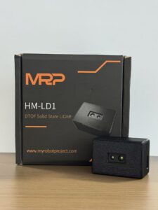
Unlike bulky rotating LiDAR sensors, the HM-LD1 is presented as a solid-state module for compact integration. It is based on SPAD dToF technology and can deliver real-time depth images and 3D point cloud data for environmental perception. The product information describes use cases including obstacle avoidance, distance detection, autonomous navigation, smart inspection, robotic vision development, UAV altitude hold, terrain following, autofocus, user presence detection, object recognition, volume measurement, and zone intrusion monitoring.
| Specification | DTOF Solid State LiDAR HM-LD1 |
|---|---|
| Technology | Solid-state LiDAR based on SPAD dToF technology |
| Dimensions | 43.5 mm × 30 mm × 26.5 mm |
| Weight | 28 g |
| Indoor Ranging Capability | 0.5–25 m |
| Outdoor Ranging Capability | 0.2–8 m |
| Ranging Accuracy | ±3 cm |
| Field of View | 60° horizontal × 45° vertical |
| Resolution | 40 × 30 |
| Frame Rate | 10 fps |
| Interface | UART / UDP / UVC |
| Operating Temperature | -20 ℃ to 60 ℃ |
| Power Consumption | 1.2 W |
| Supported Development Platforms | x86 Windows, x86 Linux, ARM Linux SDK support |
View Product Details & Pricing ➔
Download the DTOF SSL HM-LD1 Product Brochure
Where HM-LD1 Fits Best
The HM-LD1 fits applications where compact real-time depth sensing is more important than long-range survey mapping. Suitable project categories include compact AMR obstacle detection, UAV altitude hold and terrain following, embedded depth cameras, security zone intrusion monitoring, smart inspection devices, object detection, distance measurement, robotic vision development, and prototype-to-deployment perception modules.
✅ Good-fit applications are usually the ones where the system needs a compact sensing window, practical range, low weight, and straightforward data output. If the goal is building a dense city-scale map, this is not the same class of sensor as a high-end survey platform. If the goal is giving a robot, drone, smart camera, or industrial device useful 3D awareness in a compact package, the fit becomes much stronger.
Why Solid-State dToF Matters for Embedded Teams
Solid-state dToF matters because embedded teams often face strict limits on volume, weight, power, and integration complexity. A compact module with UART, UDP, and UVC interfaces can support multiple development paths. SDK support for x86 Windows, x86 Linux, and ARM Linux can reduce development friction when moving from PC-based testing to embedded deployment.
In real product work, integration time is money. A module that can be tested quickly on a PC, then moved into a Linux-based embedded system, can save weeks compared with a sensor that requires a custom pipeline from day one. That does not remove the need for validation, but it gives engineering teams a cleaner starting point.
Integration Workflow for Developers
Successful LiDAR integration requires more than connecting a sensor and reading distance values. Developers should define the perception goal, mount the module correctly, select the right interface, validate data quality, and integrate the output into the software stack that controls the robot, drone, camera, or industrial system.
Step 1 — Define the Perception Task
⚙️ Start by defining the exact task. Does the system need to detect obstacles within 3 m, maintain UAV altitude above ground, build a simple occupancy map, detect intrusion inside a zone, estimate object volume, or trigger autofocus based on subject distance? The task determines the required range, accuracy, field of view, frame rate, processing pipeline, and mounting position.
Look, vague requirements cause bad sensor choices. “We need LiDAR” is not a requirement. “We need to detect matte black obstacles from 0.5 m to 4 m while the robot moves at walking speed indoors” is much closer to a usable engineering target. The more specific the sensing task, the easier it is to decide whether the module is the right fit.
Step 2 — Select Mounting Position
⚙️ Mounting position affects data quality. Engineers should consider height, angle, vibration isolation, field of view coverage, and possible occlusion from frames, housings, propellers, robot shells, or protective covers. Optical surfaces should remain clean, and the module should be mounted securely enough to prevent measurement instability caused by vibration or shifting alignment.
Step 3 — Choose Interface
⚙️ Interface selection should match the host system. UVC may be useful for fast PC visualization or camera-style workflows. UDP may be useful for streaming data to a higher-level processor. UART may suit embedded control loops or microcontroller-based systems when bandwidth and data format requirements are manageable. The best interface is the one that supports the needed data rate and software architecture with the least unnecessary complexity.
Step 4 — Calibrate and Validate
⚙️ Validation should use known targets at known distances. Test dark objects, bright objects, reflective materials, low-reflectivity materials, indoor lighting, outdoor sunlight, expected temperature conditions, and the actual motion profile of the platform. Indoor and outdoor performance should be tested separately because ambient light and surface conditions can change range and confidence.
In the shop, this is where disciplined teams separate themselves. They do not just power the sensor, see numbers changing, and move on. They measure repeatability, latency, false detections, missed detections, mounting effects, and behavior under expected abuse. That kind of testing prevents expensive surprises after the device is already inside a robot, drone, or production machine.
Step 5 — Integrate with Software Stack
⚙️ LiDAR output may feed ROS or ROS 2 pipelines, SLAM systems, obstacle grids, flight controller altitude logic, AI perception systems, zone detection algorithms, industrial gateways, or edge computing devices. Teams evaluating a compact module for these workflows can review the DTOF Solid State LiDAR HM-LD1 specifications and SDK support before prototyping.
Limitations and Engineering Considerations
LiDAR is powerful, but it is not magic. Good engineering requires understanding the limitations of optical distance measurement and validating the sensor under real deployment conditions. Any vendor specification should be treated as a starting point, not a substitute for system-level testing.
Sunlight and Ambient Light
Strong sunlight can reduce effective range or confidence depending on sensor architecture, optical filtering, and target reflectivity. This is why indoor and outdoor range specifications are often different. A module that performs well indoors may have shorter usable range outdoors at midday, especially on low-reflectivity targets.
Reflectivity and Surface Materials
Surface material matters. Dark surfaces may absorb more light. Shiny surfaces may create specular reflections. Glass can create confusing or unreliable returns. Water and transparent materials can be difficult for optical sensing. Highly reflective targets may behave differently from matte surfaces. Application testing should include the materials the system will actually encounter.
Resolution Limits
A 40 × 30 depth map can be useful for compact perception, but it is not the same as a dense survey-grade point cloud. It can support obstacle zones, presence detection, distance measurement, and simple 3D awareness, but applications requiring fine object detail may need higher resolution or additional sensors.
Motion and Frame Rate
A 10 fps frame rate can support many real-time detection tasks, but fast-moving robots, high-speed automation, or rapidly changing scenes require careful validation. Engineers should test not only static accuracy but also latency, update consistency, and how the control software responds to moving obstacles.
Mechanical and Environmental Integration
Mechanical design affects LiDAR performance. Mounting stability, shock, vibration, heat dissipation, enclosure design, optical window cleanliness, cable routing, and electromagnetic compatibility all matter. Outdoor systems may also require protective housings, sealing, or cleaning strategies depending on the environment.
Safety and Compliance
Eye safety and compliance should be checked according to product documentation and target market requirements. Engineering teams should avoid assuming certification status unless it is clearly listed in the documentation for the exact module and configuration being used.
✅ The safest engineering habit is to verify the exact module, exact configuration, exact enclosure, and exact operating environment. That includes optical windows, mounting angle, software mode, power supply behavior, cable routing, and any regulatory requirements for the product category.
We’ve recently been testing the HM-LD1 compact dToF LiDAR in a variety of r…
LiDAR Technology FAQ
How does LiDAR really work, and why is it so accurate?
What is LiDAR actually used for beyond phone cameras and AR?
Is LiDAR necessary for robots, drones, or autonomous systems?
What is the difference between dToF LiDAR and solid-state LiDAR?
How should engineers evaluate a compact LiDAR module before deployment?
What is LiDAR technology best suited for in industrial automation?
📚 References & Further Reading
- Industry Standard: SOS LAB
- Related Guide: DTOF Solid State LiDAR HM-LD1






