


LiDAR Camera Guide: How to Choose the Right Depth Sensor for Robots, Drones, SLAM, and 3D Vision
Here’s the deal: choosing the right LiDAR camera is not about grabbing the sensor with the biggest range number on the datasheet. In real robot, drone, SLAM, 3D vision, inspection, and embedded AI projects, the only question that matters is whether the sensor gives you trustworthy depth data in the conditions where the machine actually works. A module that behaves beautifully on an indoor bench can fall apart in outdoor sunlight. A high-resolution 3D camera may look great in a demo but be too heavy for a UAV. A rotating LiDAR may produce excellent scans but draw more power, cost more, and create mechanical headaches your team does not need. Industrial buyers have to look at depth accuracy, field of view, frame rate, point cloud quality, interface options, SDK support, environmental robustness, and the total amount of engineering effort required to get the sensor into a finished product.
This guide walks through how LiDAR cameras work, how they compare with stereo cameras, ToF cameras, RGB-D sensors, and 2D LiDAR, and how to choose the right depth sensor for AMRs, AGVs, drones, SLAM, obstacle avoidance, inspection, and 3D perception. It also includes a practical selection checklist and a real product example: the DTOF Solid State LiDAR HM-LD1, a compact SPAD dToF module with depth map and point cloud output, 0.5–25 m indoor ranging, 0.2–8 m outdoor ranging, ±3 cm accuracy, 60° × 45° FOV, UART/UDP/UVC interfaces, and only 28 g weight.
Table of Contents
- 👉 What Is a LiDAR Camera?
- 👉 How a LiDAR Camera Works
- 👉 LiDAR Camera vs Other Depth Sensors
- 👉 Key LiDAR Camera Specifications to Compare
- 👉 LiDAR Camera Applications in Robots, Drones, SLAM, and 3D Vision
- 👉 Integration: Interfaces, SDKs, and Development Platforms
- 👉 Product Example: DTOF Solid State LiDAR HM-LD1
- 👉 LiDAR Camera Selection Checklist
- 👉 Common LiDAR Camera Buying Mistakes
- 👉 FAQ
What Is a LiDAR Camera?
A LiDAR camera is a depth-sensing device that uses laser-based distance measurement to understand the geometry of a scene. A regular RGB camera records color, brightness, texture, and visual appearance. A LiDAR camera measures how far objects are from the sensor. That output may show up as a depth image, a distance matrix, a point cloud, or a 3D spatial data stream. In industrial robotics, that distinction matters. Machines often need to know not just what something looks like, but where it is, how far away it is, whether it blocks the route, and how the robot should move around it without guessing.
LiDAR Camera Definition for Industrial Buyers
For industrial buyers, a LiDAR camera should be treated as a practical 3D perception component, not a consumer imaging accessory. It can support obstacle detection, distance measurement, occupancy mapping, autonomous navigation, zone monitoring, and robotic vision development. The term may describe several related device classes, including solid-state dToF LiDAR modules, 3D Time-of-Flight cameras, scanning LiDAR systems, RGB-D cameras, and integrated perception modules. The common purpose is simple: give machines direct spatial information. In this context, terms such as depth image, point cloud, 3D perception, Time-of-Flight, dToF, SPAD, mapping, and obstacle detection are not marketing fluff. They describe real engineering outputs and real system behavior.
Why “Camera” Can Be Misleading
Look, the word “camera” can throw people off. Many LiDAR cameras are not built to produce pretty, photorealistic images. A standard camera may capture millions of pixels, but those pixels do not automatically provide reliable metric distance. A compact LiDAR camera may have a lower depth resolution, such as 40 × 30, yet still be highly useful because every measurement cell contains distance information. For an AMR avoiding a pallet, a UAV holding altitude, or a security device monitoring a zone, dependable distance can matter far more than a beautiful color frame. Engineers should compare LiDAR cameras by application fit, not by consumer camera expectations.
When a LiDAR Camera Is Better Than a Regular Camera
A LiDAR camera becomes especially valuable when visual appearance is not enough. Standard cameras can struggle with low-texture surfaces, uniform walls, repeated patterns, dark scenes, strong backlighting, shadows, glare, and poor illumination. In the shop, that can mean a robot trying to detect a matte black object, a blank wall, a low pallet edge, or a person standing in a poorly lit aisle. Direct distance sensing gives the system another layer of reliability. For teams building visual navigation stacks, it is also worth understanding common visual-inertial weaknesses; see this related guide on visual inertial odometry issues.
How a LiDAR Camera Works
A LiDAR camera works by emitting light, receiving reflected signals, and calculating distance from the travel behavior of that light. The concept sounds straightforward, but reliable LiDAR perception takes careful engineering. The sensor must emit a controlled optical signal, detect weak reflected photons, reject noise from ambient light, process many measurements, and output usable depth data at a practical frame rate. Performance depends on target reflectivity, distance, angle of incidence, sunlight, calibration, optical design, processing algorithms, and how the module is physically installed.
Time-of-Flight Distance Measurement
Time-of-Flight measurement is one of the core principles behind a LiDAR camera. The sensor emits light toward the scene and measures how long it takes for the reflected signal to return. Because the light travels to the object and then back to the receiver, the distance is calculated using the round-trip time. In plain English, distance equals the speed of light multiplied by travel time, divided by two. Since light moves extremely fast, the sensor needs precise timing circuits and sensitive detection electronics. Accuracy depends not only on timing, but also on signal strength, surface reflectivity, ambient light, optical alignment, calibration, and signal processing.
Direct ToF vs Indirect ToF
Direct Time-of-Flight, often written as dToF, measures the actual return time of photons. It is commonly used when longer range, robust distance measurement, and compact laser-based sensing are important. Indirect Time-of-Flight, often written as iToF, estimates distance by measuring the phase shift between emitted and received light. iToF is widely used in many RGB-D and short-range depth camera systems. Neither technology wins every job. Industrial buyers should compare actual range, accuracy, outdoor behavior, field of view, frame rate, power consumption, SDK support, mechanical size, and integration path instead of choosing only by the technology label.
SPAD Sensors and Solid-State LiDAR
SPAD stands for Single-Photon Avalanche Diode. A SPAD detector can respond to extremely weak photon returns, which makes it useful in compact direct Time-of-Flight LiDAR modules. SPAD dToF architecture is attractive for embedded robots, drones, smart devices, and industrial perception systems because it can deliver useful depth information without a large rotating scanning assembly. Solid-state LiDAR also reduces mechanical complexity. With no spinning motor or rotating mirror assembly, the sensor is easier to package, mount, and protect. That makes solid-state modules especially relevant for forward-facing obstacle detection, UAV payloads, fixed-zone monitoring, and compact robotic platforms.
From Depth Map to Point Cloud
A LiDAR camera may output a depth map, a point cloud, or both. A depth map stores distance values in a grid, similar to an image where each pixel represents distance instead of color. A point cloud converts those depth values into 3D coordinates that describe measured surfaces in space. Depth maps are often efficient for embedded processing because they are compact and easy to analyze. Point clouds are useful for mapping, 3D visualization, occupancy grids, SLAM, volume measurement, and spatial analytics. For industrial navigation projects, GNSS, IMU, and positioning modules may also be part of the perception stack; companies such as u-blox provide useful context around positioning technologies.
LiDAR Camera vs Other Depth Sensors
Choosing a LiDAR camera means understanding how it stacks up against other sensing technologies. A robot or drone may use RGB cameras, stereo cameras, structured light cameras, 2D LiDAR, rotating 3D LiDAR, ultrasonic sensors, radar, IMUs, and wheel odometry. Each sensor has strengths and weaknesses. The best perception architecture is often not one magic sensor. It is a carefully designed combination that matches the environment, safety requirements, compute platform, and cost target.
LiDAR Camera vs RGB Camera
RGB cameras are excellent for classification, visual inspection, label recognition, color detection, object identification, semantic AI, and human-readable video. But an RGB camera does not directly measure distance. Depth must be inferred from stereo disparity, object size assumptions, motion, neural networks, or external calibration. A LiDAR camera provides metric distance output, making it more dependable for obstacle detection, spatial measurement, and navigation support. In many robots, the two technologies work best together: the RGB camera helps identify what an object is, while the LiDAR camera helps determine where it is.
LiDAR Camera vs Stereo Camera
Stereo cameras estimate depth by comparing two images captured from slightly different positions. They work well in textured scenes with good lighting and stable calibration. They can struggle with blank walls, reflective floors, repetitive patterns, darkness, overexposure, and motion blur. LiDAR measures distance directly, so it can perform better in scenes where image texture is limited. Stereo cameras may provide richer visual data and higher image resolution, while compact LiDAR modules can offer more reliable geometry in a defined field of view. For SLAM and autonomous navigation, many systems benefit from using both.
LiDAR Camera vs Structured Light Camera
Structured light cameras project a known pattern onto a scene and measure how that pattern deforms. They can be accurate at close range indoors, which makes them useful for face scanning, gesture recognition, desktop 3D capture, and short-range object measurement. The limitation is that sunlight and long distance can reduce pattern visibility. For outdoor robots, drones, inspection devices, and longer-range obstacle detection, dToF LiDAR may be more suitable because it is designed around active laser distance measurement instead of projected pattern recognition.
LiDAR Camera vs 2D LiDAR
2D LiDAR scans a single plane and is commonly used in AGV navigation, AMR safety zones, warehouse route following, and planar obstacle detection. It is reliable and well understood, but it can miss obstacles outside the scan plane. A low table edge, hanging object, ramp, pallet fork, uneven terrain, or object above the scan height may not be detected. A LiDAR camera or 3D depth sensor captures area depth, which helps machines understand more of the scene. In practical robot design, 2D LiDAR may provide planar navigation while a LiDAR camera adds forward-facing 3D perception.
LiDAR Camera vs 3D Spinning LiDAR
Mechanical 3D spinning LiDAR can generate wide-area or 360° point clouds, making it powerful for mapping, autonomous systems, and broad environmental perception. The tradeoff is size, weight, cost, power consumption, and mechanical complexity. A solid-state LiDAR camera is usually more compact and easier to integrate into drones, smart devices, embedded vision systems, and fixed-direction robot sensing. It may not replace a full-surround mechanical LiDAR, but it can provide efficient short-to-mid-range depth perception where coverage, payload, and cost must be controlled.
| Sensor Type | Strengths | Limitations | Best Fit |
|---|---|---|---|
| LiDAR Camera | Direct depth, point cloud output, reliable geometry | Resolution and range vary by module | Robots, drones, SLAM, obstacle avoidance |
| RGB Camera | Color, texture, AI recognition | No direct depth measurement | Visual inspection, object classification |
| Stereo Camera | Passive depth and visual data | Needs texture, lighting, and calibration | VIO, visual SLAM, indoor navigation |
| 2D LiDAR | Reliable planar scanning | Misses obstacles outside scan plane | AGV navigation, safety zones |
| Structured Light | High short-range indoor detail | Sunlight sensitivity and limited range | Face scanning, close-range 3D capture |
Key LiDAR Camera Specifications to Compare
Industrial buyers should compare LiDAR camera specifications against real mission conditions. A datasheet maximum range is only one piece of the story. The right evaluation includes indoor range, outdoor range, minimum range, depth accuracy, repeatability, field of view, resolution, frame rate, latency, interface options, SDK support, weight, power consumption, temperature range, and mechanical integration requirements.
Range: Indoor, Outdoor, Minimum, and Maximum
Maximum range is not one universal number. Indoor range, nighttime range, outdoor range, and range under strong sunlight can be very different. Sunlight adds optical noise, dark targets return fewer photons, and angled surfaces can reflect light away from the receiver. Buyers should ask for test conditions, target reflectivity, ambient light level, integration time, accuracy at distance, and confidence behavior. For example, the DTOF Solid State LiDAR HM-LD1 specifies indoor ranging from 0.5–25 m and outdoor ranging from 0.2–8 m. The product details also describe useful outdoor measurement at 8 m on a clear summer day with approximately 80,000 lux conditions.
Accuracy and Repeatability
Accuracy describes how close the measured distance is to the true distance. Repeatability describes how consistently the sensor produces similar measurements under the same conditions. For robots, ±3 cm accuracy can be highly useful for obstacle avoidance, distance detection, docking support, navigation assistance, and spatial awareness. However, accuracy can change with surface reflectivity, incidence angle, ambient light, temperature, vibration, motion, and calibration. Buyers should test representative materials such as black rubber, cardboard, metal, glass, concrete, painted walls, vegetation, and reflective packaging if those targets appear in the real environment.
Field of View
Field of view defines how much of the scene the LiDAR camera can observe. A wider horizontal FOV helps a robot see more of its path, while vertical FOV matters for ramps, curbs, shelves, pallets, hanging objects, ground features, and terrain changes. A narrower FOV may be useful for focused distance measurement or longer-distance targeting, but it may miss side obstacles. HM-LD1 provides a 60° horizontal × 45° vertical FOV, making it suitable for compact forward-facing perception, area monitoring, UAV terrain awareness, and embedded obstacle detection.
Resolution
LiDAR camera resolution should not be judged the same way as RGB camera resolution. A 40 × 30 depth resolution means 1,200 measurement points per frame. That is not meant for high-detail photorealistic room scanning, but it can be very useful for embedded obstacle detection, human presence sensing, zone monitoring, altitude awareness, and low-bandwidth 3D perception. Higher resolution may improve object shape recognition and mapping density, but it also increases data volume, compute requirements, power consumption, and system cost. The best resolution is the one that supports the decision the machine has to make.
Frame Rate and Latency
Frame rate determines how often the sensor updates its depth data. HM-LD1 outputs 10 fps. For slow-to-medium-speed robots, inspection systems, smart security devices, user presence detection, and UAV altitude awareness, 10 fps can be enough. For high-speed autonomous driving, fast collision avoidance, or aggressive drone flight, the system may require higher frame rates, lower latency, sensor fusion, predictive filtering, or additional sensing layers. Engineers should calculate required update rate using robot speed, stopping distance, processing latency, actuator response, and safety margin.
Interface Options
Interface selection affects integration time and system architecture. UART is useful for microcontrollers, flight controllers, and embedded systems where compact data communication is needed. UDP is suitable for networked robotics systems, embedded Linux platforms, and industrial PCs that process sensor data over IP networks. UVC can simplify camera-style workflows by presenting the LiDAR camera as a video-class device. HM-LD1 supports UART, UDP, and UVC, giving engineering teams flexibility during prototyping, bench testing, embedded integration, and deployment.
Power Consumption, Weight, and Temperature
For drones and mobile robots, every gram and watt matters. A 28 g sensor with 1.2 W power consumption is attractive for UAV payloads, compact AMRs, mobile inspection robots, battery-powered smart devices, and embedded systems with limited thermal capacity. Temperature range is also important. HM-LD1 operates from -20 ℃ to 60 ℃, which supports many warehouse, indoor industrial, outdoor inspection, and mobile robotics environments. Mechanical placement, airflow, enclosure design, and cable routing still need to be evaluated in the final system.
LiDAR Camera Applications in Robots, Drones, SLAM, and 3D Vision
A LiDAR camera is most valuable when its depth output maps directly to a machine decision. The decision might be to slow down, stop, avoid an object, hold altitude, follow terrain, estimate volume, monitor a zone, support SLAM, or measure a hard-to-reach structure. Because LiDAR cameras provide geometry rather than only appearance, they are useful across many industrial and robotic applications.
AMR and AGV Obstacle Avoidance
Autonomous mobile robots and AGVs need reliable perception for safe movement. A LiDAR camera can support forward-facing obstacle detection, pallet detection, person detection, docking assistance, low obstacle detection, shelf awareness, and blind spot reduction. 3D depth can supplement 2D LiDAR by detecting objects above or below a planar scan. This matters in warehouses where obstacles may include pallet forks, tilted boxes, overhanging materials, carts, ramps, and human legs. A compact solid-state LiDAR camera can be placed in areas where large mechanical scanners are impractical.
Robot SLAM and Navigation
Depth maps and point clouds can support mapping, localization, occupancy grids, and path planning. In SLAM, the robot estimates its position while building or updating a map of the environment. A compact LiDAR camera can provide short-to-mid-range 3D perception around a robot, especially when combined with wheel odometry, IMU data, visual features, or 2D LiDAR. The quality of the SLAM result depends on sensor synchronization, calibration, frame rate, FOV, environmental structure, and compute resources. For teams evaluating compute requirements for mapping, see this related article on CPU vs GPU choices for SLAM.
UAV Altitude Hold and Terrain Following
Drones can use LiDAR cameras for altitude awareness, terrain following, landing assistance, and obstacle detection. A lightweight module is especially important because UAV payload affects flight time, stability, and control margin. HM-LD1 weighs only 28 g, which makes it relevant for payload-sensitive platforms. A downward-facing configuration may assist altitude hold or terrain sensing, while a forward-facing configuration may help with obstacle awareness. For a drone-specific dToF module discussion, see best dToF for drone HM-LD1 solid-state LiDAR.
Smart Inspection of Bridges, Expressways, and Dams
Inspection robots and UAVs often operate near structures that are difficult or unsafe for people to approach. A LiDAR camera can help measure standoff distance, detect surfaces, support navigation near large infrastructure, and reduce operational risk. The HM-LD1 product details highlight accurate ranging at distances up to 8 m outdoors under clear summer daylight conditions around 80,000 lux. That kind of performance is useful for bridge inspection, expressway monitoring, dam inspection, wall distance measurement, and robotic systems that must maintain safe separation from structures.
Security, Zone Intrusion, and Presence Detection
LiDAR cameras can support virtual fences, doorway sensing, zone intrusion monitoring, user presence detection, and area occupancy systems. Compared with RGB video, depth-based sensing may provide privacy advantages in some applications because the system can detect presence and location without relying on detailed facial imagery. A compact depth module can also work in lighting conditions where RGB cameras are less reliable. In smart buildings, industrial safety areas, kiosks, access control devices, and machine interaction systems, depth data can help determine whether a person or object has entered a defined zone.
Autofocus, Object Recognition, and Volume Measurement
Depth data can improve camera autofocus, object recognition, size estimation, package detection, bin monitoring, and warehouse automation. A LiDAR camera can provide distance information that helps an RGB camera focus more quickly or helps software estimate object dimensions. For logistics, depth can support volume measurement and occupancy analysis. For smart devices, it can detect user presence or object position. For robots, it can help identify whether a path is blocked, whether a shelf is occupied, or whether a surface is within reach.
Integration: Interfaces, SDKs, and Development Platforms
Integration is often where a promising sensor either becomes a real product or turns into a long engineering detour. A LiDAR camera must fit the electrical design, mechanical layout, software stack, compute platform, data pipeline, and production support model. Buyers should evaluate not only the sensor specification, but also how quickly their engineering team can access data, visualize results, write drivers, synchronize timestamps, and validate performance in the final environment.
Choosing Between UART, UDP, and UVC
UART is a practical choice for compact embedded systems, microcontrollers, flight controllers, and controller-level distance data. It is simple, familiar, and lightweight, although bandwidth can be limited. UDP is useful for robots, embedded Linux systems, industrial PCs, and networked data pipelines because it can transmit data over IP networks. UVC is valuable when the LiDAR camera can behave like a camera-class device, simplifying PC visualization and software workflows. A module that supports UART, UDP, and UVC lets teams prototype quickly, test multiple architectures, and choose the most practical deployment path.
SDK Support and Operating Systems
SDK support reduces integration risk. HM-LD1 is supported by SDKs for x86 Windows, x86 Linux, and ARM Linux. That matters for development on PCs, Raspberry Pi-style platforms, embedded Linux boards, industrial computers, and robotics prototypes. An SDK can help teams access depth frames, point cloud data, configuration parameters, and sample workflows faster than building everything from scratch. Buyers should still confirm documentation quality, sample code availability, update policy, and technical support response time before committing to production.
ROS, OpenCV, and SLAM Pipeline Considerations
Even if a product specification lists interfaces and SDKs, robotics teams should ask deeper software questions. Is there a ROS driver? Can the SDK export depth frames in a format compatible with the existing pipeline? Can it output point clouds? Are timestamps available? Is calibration data accessible? Can depth be aligned with RGB or IMU data? What coordinate frame convention is used? How are invalid points, confidence levels, saturated pixels, and out-of-range values represented? These details strongly affect SLAM, obstacle avoidance, sensor fusion, and production debugging.
Mechanical Integration
Mechanical integration affects optical performance. Engineers should consider mounting orientation, field-of-view clearance, vibration isolation, dust protection, window material, thermal design, cable routing, and EMI/EMC behavior. A transparent cover that looks acceptable to the human eye may not transmit the sensor wavelength properly. A recessed mounting position may partially block the FOV. Vibration can affect repeatability. Heat buildup in a sealed enclosure can change electronics behavior. The best practice is to test the sensor in the actual enclosure and mounting position as early as possible.
Data Processing Requirements
Low-resolution depth sensors can reduce bandwidth and compute load. This is useful when the system does not need dense photorealistic reconstruction but does need reliable geometric decisions. A compact LiDAR camera can send manageable depth data to an embedded processor, allowing the system to detect zones, obstacles, surfaces, or distance thresholds without overwhelming the CPU. For edge robotics and battery-powered devices, lower compute demand can reduce thermal load, improve runtime, and simplify software design.
Product Example: DTOF Solid State LiDAR HM-LD1
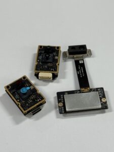
The DTOF Solid State LiDAR HM-LD1 is a compact SPAD dToF LiDAR module designed for real-time depth images and 3D point cloud data. It is suitable for obstacle avoidance, distance detection, autonomous navigation, robotic vision development, UAV altitude hold, terrain following, smart inspection, user presence detection, object recognition, volume measurement, and zone intrusion monitoring. The module is designed for robots, drones, cameras, security systems, embedded platforms, and development projects that require compact 3D depth sensing rather than a large mechanical scanning system.
HM-LD1 is based on solid-state LiDAR technology and SPAD dToF measurement. It supports 0.5–25 m indoor ranging and 0.2–8 m outdoor ranging, with ±3 cm ranging accuracy. Its 60° horizontal × 45° vertical field of view gives it practical scene coverage for forward-facing perception, compact robots, drones, and monitoring devices. With 40 × 30 depth resolution and 10 fps frame rate, it provides a compact depth stream suitable for embedded obstacle detection, area sensing, and point cloud generation. Its UART, UDP, and UVC interfaces allow flexible integration with PCs, Raspberry Pi-style platforms, embedded Linux systems, flight controllers, and industrial development environments.
| Specification | DTOF Solid State LiDAR HM-LD1 |
|---|---|
| Technology | SPAD dToF solid-state LiDAR |
| Dimensions | 43.5 mm × 30 mm × 26.5 mm |
| Ranging Capability | Indoor: 0.5–25 m; Outdoor: 0.2–8 m |
| Ranging Accuracy | ±3 cm |
| Field of View | 60° horizontal × 45° vertical |
| Resolution | 40 × 30 |
| Frame Rate | 10 fps |
| Interface | UART / UDP / UVC |
| Operating Temperature | -20 ℃ to 60 ℃ |
| Power Consumption | 1.2 W |
| Weight | 28 g |
| Development Support | SDKs for x86 Windows, x86 Linux, and ARM Linux |
| Typical Outputs | Depth image and 3D point cloud data |
| Typical Applications | Obstacle avoidance, distance detection, autonomous navigation, SLAM support, UAV altitude hold, terrain following, inspection, presence detection, volume measurement, and zone intrusion monitoring |
View Product Details & Pricing ➔
Why HM-LD1 Fits Compact Robots and UAVs
HM-LD1 is especially relevant for compact robots and UAVs because it combines depth sensing with low weight and low power consumption. At 28 g and 1.2 W, it can be considered for battery-powered systems where payload and thermal budget matter. The compact dimensions make it easier to mount inside small enclosures, on drone frames, on robot fronts, or inside smart devices. Its outdoor ranging capability up to 8 m supports practical perception tasks such as terrain following, altitude support, inspection standoff measurement, and obstacle awareness in outdoor daylight conditions.
Why HM-LD1 Fits Embedded Development
Embedded development teams benefit from interface flexibility. UART can serve controller-level integration, UDP can support Linux-based robot data pipelines, and UVC can simplify camera-like workflows on compatible systems. SDK support for x86 Windows, x86 Linux, and ARM Linux gives development teams multiple options for prototyping, testing, visualization, and deployment. This makes the module suitable for PCs, Raspberry Pi-style platforms, embedded Linux boards, flight controllers, and industrial computing platforms.
Where HM-LD1 Is Not the Best Fit
HM-LD1 should be selected for the right kind of job. It is not a high-resolution photorealistic room scanner, not a 360° mechanical LiDAR replacement, and not necessarily enough by itself for high-speed autonomous driving. Its 40 × 30 depth resolution is practical for compact embedded perception, but it should not be confused with dense 3D reconstruction systems. The strongest use case is as a compact 3D depth module within a larger perception system, especially where weight, power, integration flexibility, and reliable distance output matter more than full-surround coverage.
Product brochure: DTOF SSL HM-LD1 Product Brochure
LiDAR Camera Selection Checklist
A structured selection process helps buyers avoid overpaying for unnecessary specifications or choosing a sensor that fails in real conditions. The correct LiDAR camera depends on the environment, robot speed, required range, field of view, software platform, mechanical constraints, and validation process.
Step 1: Define the Operating Environment
⚙️ Start by defining whether the LiDAR camera will operate indoors, outdoors, or both. Consider sunlight exposure, low-light operation, dust, fog, vibration, temperature extremes, reflective targets, dark surfaces, glass, and motion. A sensor that performs well in a controlled lab may behave differently on a vibrating robot or an outdoor UAV. Environmental requirements should be documented before comparing datasheets.
Step 2: Define the Required Range
⚙️ Define the minimum detection distance, maximum detection distance, required accuracy at maximum range, and stopping distance. For collision avoidance, minimum range can be just as important as maximum range. For inspection, longer standoff distance may matter more. For drones, altitude measurement and terrain following may require stable performance over variable ground materials. Compare indoor and outdoor range separately because ambient light changes sensor behavior.
Step 3: Match FOV to the Scene
⚙️ A wide FOV helps with obstacle awareness, human presence detection, and navigation corridor monitoring. A narrow FOV may be better for focused distance measurement. Vertical FOV is important for ramps, curbs, stairs, shelves, hanging objects, ground changes, and terrain. Horizontal FOV is important for path coverage and side obstacle detection. The sensor should be mounted so the field of view is not blocked by the enclosure, frame, cables, or protective window.
Step 4: Decide Between Depth Map and Point Cloud
⚙️ A depth map is often easier to process on embedded platforms because it is compact and structured like an image. A point cloud is better for 3D visualization, mapping, SLAM, volume estimation, and spatial analytics. Some applications need both: a depth map for real-time control and a point cloud for mapping or debugging. Buyers should confirm what formats the sensor outputs and how those outputs are accessed through the SDK or interface.
Step 5: Check Mechanical and Electrical Constraints
⚙️ Weight limit, power budget, mounting space, connector type, cable routing, cooling requirements, enclosure window material, and EMI/EMC behavior all influence the final design. A lightweight LiDAR camera may be essential for UAVs. Low power consumption may be essential for battery-powered robots. Mechanical constraints should be reviewed before software integration begins because optical obstruction or poor mounting can undermine sensor performance.
Step 6: Verify Software Compatibility
⚙️ Software compatibility includes SDK availability, driver support, operating system support, timestamping, calibration access, point cloud output, depth frame format, example code, and documentation quality. Robotics teams should also ask about ROS compatibility, Linux support, ARM platform support, and synchronization with IMU or camera data. A sensor with strong hardware but weak software support can delay development and increase total project cost.
Step 7: Validate With Real Scene Testing
⚙️ Datasheets are starting points, not final proof. Real-world validation should include actual target materials, lighting conditions, robot speed, vibration, intended mounting angle, power supply, enclosure design, and data processing pipeline. Test dark objects, reflective surfaces, angled walls, outdoor sunlight, minimum range, maximum range, and motion. For production systems, repeat tests across temperature and environmental conditions to confirm reliability.
Common LiDAR Camera Buying Mistakes
Many LiDAR camera selection problems come from comparing the wrong numbers or testing too late. A disciplined evaluation process helps engineering and procurement teams choose a sensor that performs reliably in the real application.
Comparing Only Maximum Range
✅ Maximum range may be measured indoors, under low ambient light, or on high-reflectivity targets. It may not represent outdoor sunlight performance or low-reflectivity objects. Buyers should compare range under real operating conditions and request details about test setup, target reflectivity, accuracy, and confidence levels.
Ignoring Minimum Range
✅ A sensor that works well at 10 m may not detect objects very close to the robot. For collision avoidance, docking, pallet detection, and human safety zones, minimum range matters. Buyers should check whether the application requires short-range detection near the bumper, landing gear, manipulator, or enclosure.
Confusing RGB Resolution With Depth Resolution
✅ A high RGB resolution does not guarantee high-quality depth. Depth accuracy, repeatability, noise, confidence, field of view, frame rate, and outdoor performance matter more for robotic perception. A lower-resolution depth sensor may still be the right choice when the system only needs reliable distance data for control decisions.
Forgetting Outdoor Sunlight Performance
✅ Sunlight can reduce signal-to-noise ratio and shorten effective range. Outdoor range should be specified separately from indoor range. Buyers should test under expected sunlight levels, target materials, and mounting angles. Outdoor robotics, drones, and inspection systems should never rely only on indoor range claims.
Choosing a Sensor Without SDK Support
✅ A strong sensor with weak software support can delay integration. SDKs, documentation, sample code, interface clarity, and technical support are critical. Buyers should verify whether the module supports their target platform, whether data formats are documented, and whether troubleshooting support is available during integration.
Ignoring Mechanical Integration
✅ Vibration, mounting angle, enclosure windows, dirty optics, thermal buildup, cable strain, and field-of-view blockage can all affect performance. Mechanical design should be treated as part of the sensing system. The sensor should be tested in the actual housing and mounting position before final production decisions.
FAQ
What is the best LiDAR camera for high-detail room scanning?
Is LiDAR better than cameras, or should robots use both?
Can LiDAR damage phone or camera sensors?
What is the difference between a LiDAR camera and a depth camera?
Can a LiDAR camera be used for SLAM?
What range should a LiDAR camera have for robots?
Is a solid-state LiDAR camera better than a rotating LiDAR?
What interface is best for a LiDAR camera: UART, UDP, or UVC?
How important is LiDAR camera resolution?
What should industrial buyers test before choosing a LiDAR camera?
📚 References & Further Reading
- Industry Standard: u-blox positioning and navigation technologies
- Related Guide: Explore visual inertial odometry issues
- Related Guide: Best dToF for drone HM-LD1 solid-state LiDAR
- Related Guide: CPU vs GPU: choosing for SLAM
- Product Reference: DTOF Solid State LiDAR HM-LD1






