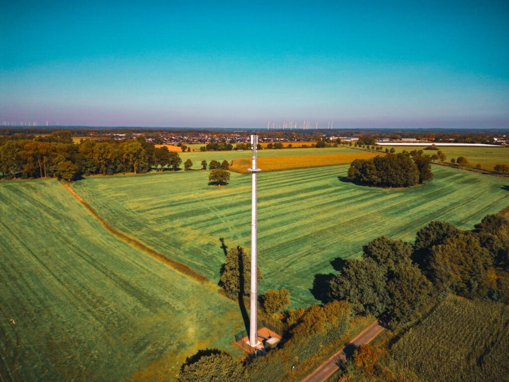
How Does LiDAR Work? The Ultimate Guide for Next-Gen Robotics & Drone Navigation
If you are trying to build a robot or a drone that actually navigates the real world without smashing into walls or dropping out of the sky, you quickly run into a hard truth: spatial perception is a brutal engineering challenge. Look, we have all tried to get by with the classics. For years, teams built navigation stacks around ultrasonic distance sensors that get baffled by carpet, wheel encoders that slip the millisecond they hit dusty warehouse concrete, or traditional optical cameras that go completely blind when a cloud passes in front of the sun. But in real-world industrial environments, these legacy systems simply do not have the speed, precision, or environmental resilience required for safety-critical operations.
Here is the deal. When an Autonomous Mobile Robot (AMR) is hauling a 1,000-pound payload down a narrow warehouse aisle, “close enough” measurements do not cut it. The robot needs to map its surroundings with millimeter-level accuracy in real time, regardless of whether it is operating under direct mid-day sunlight or in a pitch-black distribution center. This is where Light Detection and Ranging (LiDAR) comes into play. By projecting optical energy into the local environment and calculating the round-trip transition time, lidar translates physical structures into highly detailed 3D digital maps known as point clouds.
This comprehensive guide dives deep into the high-performance hardware architecture of modern lidar systems. We will unpack the optical physics of active ranging, contrast direct and indirect Time-of-Flight systems, explore the silicon-level mechanics of Single-Photon Avalanche Diodes (SPADs), and look at how field engineers integrate this hardware to solve localization, mapping, and obstacle avoidance challenges.
Table of Contents
- 👉 1. The Fundamental Physics of LiDAR
- 👉 2. Inside the Silicon: SPADs & Advanced Optical Sensing
- 👉 3. Industrial Applications for Robotics and UAVs
- 👉 4. Spotlight: Professional Hardware Specifications
- 👉 5. Comparative Evaluation: LiDAR vs. Cameras vs. RADAR
- 👉 6. Engineering Deep-Dive & Integration FAQ
1. The Fundamental Physics of LiDAR
To understand why lidar is the gold standard for spatial navigation, you need to understand the physical principles that govern its operation. At its absolute core, lidar is an active optical sensing system. Unlike passive camera systems, which rely on external ambient light sources—be it sunlight, overhead sodium lamps, or fluorescent tubes—and are highly susceptible to shifting shadows and dark corners, a lidar sensor generates its own illumination. It does not care if a room is pitch black or flooded with bright light; the subsystem operates completely independent of local illumination.
A standard industrial-grade lidar operates as an intricate, closed-loop optoelectronic system. To make this work, the sensor relies on three distinct subsystems that must remain perfectly synchronized down to the picosecond level:
- ⚙️ The Optical Transmitter Subsystem: This includes the laser emitter, drive circuitry, and beam-shaping optics. Most industrial lidar platforms utilize Vertical-Cavity Surface-Emitting Lasers (VCSELs) or Edge-Emitting Lasers (EELs) that operate in the near-infrared (NIR) spectrum—typically at wavelengths of 905 nanometers or 940 nanometers. Premium, long-range survey setups often jump to 1550 nanometers, a wavelength that allows for higher output power while remaining eye-safe, though at a significantly higher component cost.
- ⚙️ The Optical Receiver Subsystem: Here, you find the receiving optics, narrow bandpass filters, and high-sensitivity photodetectors. The photodetectors are specialized semiconductor elements, such as highly responsive Avalanche Photodiodes (APDs), Silicon Photomultipliers (SiPMs), or Single-Photon Avalanche Diode (SPAD) arrays, designed to convert incoming optical signals back into electrical pulses.
- ⚙️ The Time-to-Digital Converter (TDC) Core: This is the digital stopwatch of the sensor. The processor is responsible for registering the exact launch time of the optical pulse and matching it with the arrival stamp of the returning reflection, resolving time values with picosecond resolution to ensure sub-centimeter accuracy.
For a deeper dive into the fundamental physics of light travel and ranging, check out Wikipedia’s overview of Time-of-Flight concepts.
1.1 Direct Time-of-Flight (dToF) vs. Indirect Time-of-Flight (iToF)
When you are designing or selecting a lidar system, you have to choose between two fundamentally different methods of measuring how long it takes light to travel: Direct Time-of-Flight (dToF) and Indirect Time-of-Flight (iToF).
In a Direct Time-of-Flight (dToF) design, the transmitter fires an extremely brief, high-energy laser pulse—often lasting only a few nanoseconds. The pulse leaves the emitter, bounces off the target, and travels back to the receiver. The system’s high-speed clock measures the precise physical time elapsed between transmission and reception. The distance is calculated using a straightforward physical formula:
Distance = (Speed of Light * Round-Trip Time) / 2
Because dToF measures physical time directly, it has two major advantages: it maintains high signal clarity over long distances, and it is highly resilient against ambient solar noise. By using narrow temporal gating—where the receiver only listens during the precise window when a reflection is expected—dToF systems can easily filter out random environmental photons.
Indirect Time-of-Flight (iToF), on the other hand, takes a different approach. Instead of firing brief, high-energy pulses, the emitter transmits a continuous, amplitude-modulated light wave, typically a high-frequency sine or square wave. Instead of measuring actual elapsed time, the receiver measures the phase shift between the emitted signal and the reflected wave returning from the target. The phase shift tells us how far the light traveled before bouncing back.
While iToF sensors deliver excellent spatial resolution at very close range and are cheaper to manufacture, they carry two major engineering drawbacks. First, they suffer from phase wrapping ambiguity—if an object is located past a certain distance, the phase shift wraps around, causing the sensor to miscalculate the distance. Second, they are vulnerable to multi-path interference, where reflections from multiple surfaces hit a single pixel simultaneously, causing structural measurement errors. For outdoors, long-range drone flight, and complex industrial deployments, dToF remains the industry’s preferred architecture.
1.2 Mechanical Spinning vs. Solid-State (SSL) Architectures
In the early days of autonomous vehicles, mechanical spinning lidar units dominated the field. These systems use a motorized base and physical slip rings to spin an array of laser diodes and receiver boards a full 360 degrees. While this brute-force approach delivers a wide, sweeping field of view, it introduces several mechanical points of failure that can cause issues in the shop and in the field:
- ✅ 360-degree Coverage: A single mechanical sensor can sweep an entire room, simplifying the system’s sensor layout.
- ✅ Consistent Angular Resolution: The sensor maintains uniform resolution across its entire rotation.
- ❌ Mechanical Wear and Tear: High-speed spinning slip rings and bearings wear out over time, leading to a limited operational lifetime.
- ❌ Vibration and Shock Sensitivity: When mounted on heavy construction equipment or warehouse AGVs, physical impacts can cause the internal optical alignment to drift, requiring frequent recalibration.
- ❌ Payload and Space Constraints: Dynamic mechanical housings are heavy and bulky, making them impractical for weight-sensitive drones or compact mobile robots.
Solid-State LiDAR (SSL) solves these problems by removing all moving parts. By utilizing high-density arrays of VCSEL transmitters and SPAD micro-receivers bonded directly to a static silicon substrate inside a rugged, sealed housing, SSL systems achieve exceptional durability. Without delicate spinning parts to worry about, these sensors can survive heavy drops, intense vibrations, and harsh thermal shifts, all while fitting into highly compact form factors. For team leads designing autonomous equipment for real-world environments, solid-state is the clear choice.
To review the historical evolution of optical ranging and scanning architectures, explore Wikipedia’s structural breakdown of LiDAR.
2. Inside the Silicon: SPADs & Advanced Optical Sensing
The magic of modern solid-state dToF lidar happens deep within its silicon architecture, specifically on the Single-Photon Avalanche Diode (SPAD) array. SPADs are specialized optoelectronic receiver elements fabricated using standard CMOS processes, meaning they can be produced at scale alongside digital logic gates on the same silicon die.
A SPAD is fundamentally a photodiode operated under an extreme reverse bias voltage that exceeds its breakdown voltage. This state is known as Geiger-mode. When a semiconductor is biased this far past its physical limit, the electric field across its depletion region is incredibly intense. When a single incoming photon enters this depletion region, it collides with the silicon lattice, exciting an electron and creating an electron-hole pair. The intense electric field instantly accelerates these free charge carriers, causing them to collide with other atoms and free more electrons—a process known as impact ionization. This triggers a self-sustaining avalanche process that multiplies a single photon event into a massive, measurable milliampere current pulse within picoseconds.
To reset the sensor for the next incoming photon, a quenching circuit (either passive or active) quickly lowers the bias voltage below the breakdown threshold, extinguishing the avalanche before the silicon overheats. This incredibly fast reaction loop allows the system to detect individual photons with high timing precision.
However, running a sensor with single-photon sensitivity introduced a major problem: ambient noise. In outdoor environments, direct sunlight can flood a sensor with up to 80,000 lux of background noise. If your receiver triggers on *any* incoming photon, it will constantly register false returns from background sunlight, rendering your data useless. To combat this, modern dToF sensors utilize a multi-layered filtering architecture:
- ✅ **Infrared Bandpass Filtering:** The sensor’s receiver aperture is covered with physical optical coatings that restrict incoming light to a narrow wavelength window (e.g., 905nm ± 5nm), blocking out visible daylight.
- ✅ **Time-Gated Coincidence Windows:** Since the system knows precisely when it fired its laser pulse, the digital receiver only listens during narrow time-gated windows when real reflections are expected to return, ignoring noise that arrives out of sync.
- ✅ **Spatial Coincidence Checking:** Instead of relying on a single SPAD pixel, the sensor groups clusters of SPADs into macro-pixels. The system only registers a valid return if multiple neighboring SPADs trigger at the exact same time, successfully filtering out random background photons.
- ✅ **Statistical Histogram Integration:** Over multiple rapid-fire laser cycles, the sensor compiles raw returns into a spatial time-of-flight histogram. While random environmental noise is spread evenly across the timeline, true physical obstacles create a distinct, sharp signal peak, allowing the internal DSP to isolate and extract highly accurate distance measurements.
3. Industrial Applications for Robotics and UAVs
In physical warehouses, manufacturing lines, and open airspace, autonomous systems rely on solid-state lidar modules to build the spatial awareness needed for safe, efficient operation.
3.1 Real-Time SLAM & Spatial Localization
Simultaneous Localization and Mapping (SLAM) is the math-heavy computational process of building a map of an unfamiliar environment while tracking a robot’s location within that same map. Solid-state lidar is perfect for this task because it generates high-frequency, low-latency distance vectors. In both 2D and 3D SLAM, the software takes consecutive coordinate sweeps and runs scan-matching algorithms, like Iterative Closest Point (ICP) or Normal Distributions Transform (NDT), to align the new data with the existing map. This allows the system to calculate its exact translational and rotational movement, compensating for wheel slip on slick concrete and letting the robot navigate reliably over long shifts.
3.2 Next-Gen Obstacle Avoidance Systems
In busy, fast-paced warehouse environments, AMRs must detect and navigate around shifting hazards in real time. Standard 1D rangefinders or basic 2D line scanners easily miss low-profile hazards on the floor (like dropped pallet forks) or hanging overhead obstacles (like open cabinet doors or structural beams). Solid-state lidar sensors provide a wide, three-dimensional field of view, capturing dense spatial coordinates of everything in the robot’s path. This high-density point cloud feeds directly into path-planning software, such as the ROS Nav2 costmap server, where key obstacle coordinates are mapped into keep-out zones. Any encroachment instantly triggers path updates or emergency braking protocols, keeping workers and equipment safe.
3.3 UAV Terrain Following & Altitude Hold
For industrial drones, maintaining a constant height above uneven ground is critical for aerial mapping, precision agricultural spraying, and power line inspections. Standard barometric altimeters fluctuate with wind gusts and air pressure shifts, and GPS vertical coordinates lack the precision needed for low-altitude flight. Mounting a lightweight solid-state lidar facing straight down gives the autopilot (like PX4 or ArduPilot) precise, real-time distance measurements to the ground, independent of shadows or soil texture. The drone adjusts its flight controllers dynamically at up to 10 Hz, allowing it to trace the contours of the terrain below—even when flying over thick brush, shifting crops, or low-reflectivity asphalt.
4. Spotlight: Professional Hardware Specifications
To help you evaluate and integrate these systems into your own designs, we have detailed the technical architectures of our leading solid-state lidar and thermal imaging platforms below.
DTOF Solid State LiDAR HM-LD1
The HM-LD1 is an industrial-grade solid-state lidar module powered by advanced SPAD dToF technology. Optimized for robotics, drones, and precision obstacle avoidance, it delivers real-time 3D depth maps and point-cloud data under diverse operational conditions. Measuring a compact 43.5mm x 30mm x 26.5mm and weighing only 28 grams, the HM-LD1 is exceptionally easy to integrate into weight-sensitive platforms or narrow robotic structures.

Figure 1: Ranging principle and optical path design of the HM-LD1 Solid State LiDAR.
Technical Documentation
📄 Access the full technical brochure for detailed electrical interfaces and pinout diagrams: DTOF SSL HM-LD1 Product Brochure
HM-LD1 Detailed Specifications
| Parameter | Value / Specification |
|---|---|
| Dimensions | 43.5mm * 30mm * 26.5mm (Alternative Housing: 43.5mm * 43.5mm * 28.5mm) |
| Weight | 28g (Ideal for UAV payload limits) |
| Ranging Range (Indoor) | 0.5m – 25m |
| Ranging Range (Outdoor) | 0.2m – 8m (Maintains accuracy in high ambient solar conditions up to 80,000 lux) |
| Ranging Accuracy | ±3cm |
| Field of View (FOV) | 60° (Horizontal) x 45° (Vertical) |
| Resolution | 40 * 30 Pixels |
| Frame Rate | 10fps |
| Communication Interfaces | UART / UDP / UVC (Seamless plug-and-play across different hardware hosts) |
| Operating Temperature | -20 °C to 60 °C (Industrial-grade thermal rating) |
| Power Consumption | 1.2 W |
The HM-LD1 is supported by cross-platform SDKs covering x86 Windows, x86 Linux, and ARM Linux. This makes it a highly flexible development platform for rapid integration with boards like the Raspberry Pi, NVIDIA Jetson, or custom flight controllers.
Drone With Thermal Camera AP-SG
The AP-SG is an advanced multi-spectral imaging payload engineered for commercial UAVs. This payload integrates zoom, thermal, and wide-angle cameras onto an active 3-axis stabilized gimbal, providing long-range monitoring and temperature tracking capabilities that pair perfectly with lidar-navigated flight hardware.

Figure 2: AP-SG high-resolution triple-sensor thermal and optical imaging subsystem.
Technical Documentation
📄 Access the full drone payload manual: AP-SG_Product_Brochure
AP-SG Detailed Specifications
| Parameter | Value / Specification |
|---|---|
| Dimensions | 75mm (Height) * 65mm (Width) * 67mm (Length) |
| Primary Video Recording | 4K Ultra-HD @ 30 fps |
| Thermal Camera Resolution | 640 X 512 @ 30 Hz (Perfect for dynamic, smooth thermodynamic video tracking) |
| Thermal Pixel Pitch | 12 μm |
| Temperature Measurement Range | -20 °C to 450 °C |
| Camera Field of View (FOV) | 79° (Wide-Angle) / 15° (Telephoto with 43x Hybrid Zoom) |
| Optical Focal Length | 4.74mm (Wide-Angle) / 25mm (Telephoto) |
| Max Signal Range | 10km (FCC Standard Compliance) |
| Wireless Protocol & Frequency | 5.725 GHz to 5.850 GHz supporting 802.11A/B/G/N/AC/AX with 2×2 MIMO |
| Physical Interfaces | SD Card Slot, SBUS, CVBS, UART, Ethernet Port, Dedicated Fan Power |
Equipped with a Sony 4K imaging sensor and an active 3-axis gimbal that offsets flight vibrations, the AP-SG delivers stable, crystal-clear imagery. When combined with a lidar-driven altitude-hold sensor, the AP-SG serves as an exceptionally efficient aerial payload for powerline grid inspections and industrial search-and-rescue mapping.
5. Comparative Evaluation: LiDAR vs. Cameras vs. RADAR
To help you select the optimal sensor configuration for your robotics or drone project, this table compares the strengths and trade-offs of the three primary spatial perception technologies.
| Engineering Vector | LiDAR (e.g., HM-LD1) | Vision Cameras (Stereo/Mono) | RADAR |
|---|---|---|---|
| Underlying Physics | Active optical time-of-flight measurements using near-infrared light. | Passive detection of ambient light, extracting spatial data mathematically. | Active radio-wave timing tracking via Doppler frequency modulations. |
| Spatial Precision | Extremely high (millimeter to centimeter scale precision). | Moderate (relies heavily on computing performance and spatial baselines). | Low-to-moderate spatial resolution, but highly accurate speed calculation. |
| Low-Light Performance | Exceptional. Independent of external environmental light. | Extremely poor. Suffers from high sensor noise and lost frames. | Exceptional. Unaffected by light levels or complete darkness. |
| Sunlight Immunity | High. Regulated by narrow bandpass filters & dToF histograms. | Poor. Highly prone to lens flare and contrast washout. | Absolute. Emitted radio spectra are completely unaffected by daylight. |
| Compute Overhead | Minimal. Delivers raw coordinate metrics over simple serial/UDP. | Very high. Requires powerful GPUs or edge TPUs for real-time vision. | Minimal to moderate. Requires basic DSP algorithms. |
| Payload Weight | Extremely low (modern solid-state sensors are only 28 grams). | Low to moderate (depending on lenses and gimbal mounts). | Moderate to high (requires large metal waveguides and shielding). |
a short-flex design and a long-flex design for different robotics and UAV d…
6. Engineering Deep-Dive & Integration FAQ
How does LiDAR actually work for robotics navigation?
Is LiDAR strictly necessary for AGV/AMR and drone development, or can cameras suffice?
What is the future of LiDAR, and why is solid-state superior to rotating mechanical systems?
📚 References & Further Reading
- Industry Standard: Learn more about physics calculations on Wikipedia’s Time-of-Flight article.
- Industry Standard: Review the optical dynamics of laser scanners on Wikipedia’s LiDAR Breakdown.
- Related Guide: Explore practical firmware integration on the DTOF Solid State LiDAR HM-LD1 webpage.