


High Sensitivity Accelerometer for Low-Vibration Robotics and Industrial Sensing
Low-vibration robots, autonomous platforms, precision inspection systems, and industrial machines all depend on motion data that stays steady when movement is subtle. A conventional accelerometer may handle a large shock or a fast change in motion without trouble, yet still produce unreliable navigation or control results when the system needs to detect small changes in velocity, orientation, or vibration.
Here’s the deal: “high sensitivity” is not a complete performance description by itself. The practical question is whether the entire inertial measurement system delivers low bias instability, low velocity random walk, controlled bandwidth, reliable calibration, low cross-axis error, and stable operation across the expected temperature range.
The Industrial High Precision IMU HM-G12 is built for this type of application. It combines three-axis gyroscopes, three-axis accelerometers, onboard processing, full-temperature calibration, and industrial communication in a compact 30 mm × 30 mm × 10.6 mm module. Its accelerometer specifications include 0.016 mg bias instability, 0.018 m/s/√h velocity random walk, a ±16 g measurement range, and 200 Hz accelerometer bandwidth.
The result is a compact six-axis inertial sensing platform for robotics, drones, industrial motion control, machine monitoring, and other systems where stable data matters more than simply detecting large acceleration events. In the shop, that distinction matters. A sensor that detects a shock is not automatically a sensor that can support accurate motion estimation.
Table of Contents
- 👉 What Is a High Sensitivity Accelerometer?
- 👉 How High Sensitivity Accelerometers Work
- 👉 Sensitivity, Noise, Bias, and Resolution Explained
- 👉 Why Low-Vibration Robotics Need Stable Inertial Data
- 👉 How to Select an Industrial Accelerometer
- 👉 HM-G12 High Precision IMU Specifications
- 👉 Applications for High Sensitivity Inertial Sensing
- 👉 Installation, Interface, and Integration Guidance
- 👉 Common Measurement Errors and Limitations
- 👉 High Sensitivity Accelerometer FAQ
- 👉 Request HM-G12 Integration Support
What Is a High Sensitivity Accelerometer?
A high sensitivity accelerometer is designed to detect relatively small changes in acceleration with useful repeatability and low measurement uncertainty. The term can refer to the electrical response of the sensing element, the minimum detectable acceleration, the output resolution, or the overall quality of the measurement system. Those ideas are connected, but they are not interchangeable.
Sensitivity describes how much the sensor output changes in response to an input acceleration. Resolution describes the smallest change that can be distinguished from the complete system’s noise and uncertainty. Accuracy describes how closely the measurement represents the actual acceleration. Stability describes how consistently the result holds over time, temperature, and operating conditions.
For industrial motion sensing, high sensitivity has to be evaluated alongside noise, bias stability, bandwidth, range, cross-axis behavior, temperature response, calibration, and mechanical installation. A sensor with a high nominal sensitivity but excessive bias drift can produce poor long-term navigation results. On the other hand, an accelerometer with a broader range may be the better choice for a robot that sees both small vibration and occasional shocks.
Sensitivity Versus Measurement Quality
Measurement quality comes from the entire signal chain. The sensing element, analog front end, analog-to-digital converter, onboard processing, calibration data, communication interface, host software, power supply, and mounting structure can all influence the result delivered to a controller.
When reviewing a sensor, look at these specifications together:
- ✅ Accelerometer range
- ✅ Bias instability
- ✅ Bias stability
- ✅ Velocity random walk
- ✅ Noise density or equivalent noise performance
- ✅ Bandwidth
- ✅ Sampling or output rate
- ✅ Cross-axis sensitivity
- ✅ Nonlinearity
- ✅ Temperature coefficient
- ✅ Calibration method
- ✅ Mechanical mounting quality
The HM-G12 provides an accelerometer range of ±16 g and a 200 Hz accelerometer bandwidth. It also provides an accelerometer bias instability specification of 0.016 mg and velocity random walk of 0.018 m/s/√h. Those numbers are more useful for evaluating low-vibration industrial sensing than the phrase “high sensitivity” by itself.
High Sensitivity Does Not Mean Unlimited Resolution
Resolution is the smallest meaningful change that can be distinguished from system noise. A digital output may contain many numerical counts, but that does not mean every count represents a physically useful change. The sensor, analog front end, conversion process, calibration, mounting structure, and data-processing chain all affect effective resolution.
For that reason, engineers should evaluate the complete error budget rather than selecting a part based only on digital output resolution or nominal scale factor. A stable sensor with controlled bias and noise can produce more useful data than a nominally sensitive sensor whose offset changes substantially during operation.
How High Sensitivity Accelerometers Work
Most industrial accelerometers use a microelectromechanical systems, or MEMS, sensing structure. A proof mass is suspended inside the device. When the sensor body accelerates, the proof mass moves relative to its frame. The sensor electronics measure that movement and convert it into an acceleration value.
MEMS Sensing Principle
A simplified MEMS accelerometer contains a proof mass, springs or flexures, a differential sensing structure, signal-conditioning electronics, analog-to-digital conversion, and calibration or compensation software. Changes in the proof mass position relate to the force acting on the structure. The resulting signal is converted into a digital measurement and transmitted to a host controller.
In a closed-loop accelerometer, the electronics apply a restoring force to keep the proof mass near its neutral position. The feedback signal required to maintain that position becomes the measured acceleration. Closed-loop architectures can improve linearity, dynamic behavior, and repeatability compared with an entirely open-loop approach.
Packaging also matters. Mechanical stress, package deformation, temperature gradients, electrical noise, and structural resonance can all affect the reported output. Look at the sensor as part of the intended machine, not as an isolated component sitting on a test bench.
Six-Axis IMU Architecture
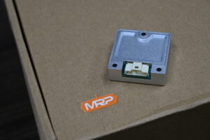
The HM-G12 is a six-axis IMU that combines three-axis accelerometer measurement, three-axis gyroscope measurement, an onboard MCU, digital UART output, factory calibration, and error compensation. The accelerometer measures linear acceleration along three orthogonal axes. The gyroscope measures angular velocity around those same axes.
Combining both sensor types lets a control system estimate movement, orientation, vibration, and changes in motion more effectively than an accelerometer alone. The onboard processing provides a defined module-level interface for embedded systems that need compact inertial data without building a complete sensor subsystem from individual components.
Why the Gyroscope Matters
An accelerometer can detect the effect of gravity and linear motion, but it cannot independently provide complete rotational information during dynamic movement. A gyroscope supplies angular-rate data that helps a robot or industrial controller distinguish rotation from translation.
The HM-G12 gyroscope includes a 200 Hz bandwidth, angular random walk of no more than 0.15°/√h, bias instability of no more than 1.4°/h, bias stability of no more than 4°/h, and orthogonality error of no more than 0.05°. These specifications matter when the accelerometer is being used as part of a complete navigation, stabilization, or motion-control system.
Take a mobile robot turning along a curved path. The acceleration components change as the vehicle rotates. Gyroscope measurements provide angular-rate information that can be combined with accelerometer data and external references to produce a more reliable estimate of the vehicle’s actual motion.
Sensitivity, Noise, Bias, and Resolution Explained
Industrial buyers need to look beyond sensitivity because small errors can accumulate quickly when acceleration and angular-rate data are integrated over time. A sensor can respond strongly to a small input and still provide poor navigation results if its zero offset drifts, its noise is excessive, or its temperature response is poorly controlled.
Bias Instability
Bias is the sensor output that remains when the actual input is zero or known. Bias instability describes how much that offset changes over time under stable conditions. A changing bias can accumulate into position or orientation error, especially when the system integrates acceleration or angular rate.
The HM-G12 accelerometer bias instability is specified at 0.016 mg. That is an important performance indicator for low-vibration systems that need stable short- and medium-duration inertial data. The published value should still be interpreted in the context of the manufacturer’s test conditions, calibration procedure, measurement duration, and operating environment.
Bias Stability
Bias stability is related to bias repeatability and drift under defined operating conditions. It can be influenced by time, temperature, power conditions, mechanical stress, and calibration quality. The HM-G12 lists accelerometer bias stability at 0.055 mg and gyroscope bias stability at no more than 4°/h.
When comparing products from different suppliers, ask for the applicable test method. Confirm whether the specifications were measured at a fixed temperature, across a defined temperature range, or after a particular warm-up period. A value without test context should not be treated as a complete prediction of field performance.
Velocity Random Walk
Velocity random walk is an integrated measure of accelerometer noise. It indicates how random acceleration errors can accumulate into velocity uncertainty over time. It is commonly expressed in m/s/√h and is especially relevant to inertial navigation, stabilization, motion estimation, and low-vibration platforms.
The HM-G12 provides a velocity random walk specification of 0.018 m/s/√h. This helps engineers estimate how random acceleration errors may affect velocity calculations when no external position or velocity reference is available. Filtering and sensor fusion can reduce the impact of some errors, but no algorithm can remove every underlying sensor limitation.
Angular Random Walk
Angular random walk applies to gyroscopes rather than accelerometers. It describes how gyroscope noise can accumulate into angular uncertainty. The HM-G12 gyroscope angular random walk is specified as no more than 0.15°/√h.
This metric belongs in the review because a six-axis IMU must be evaluated as a complete inertial system. A strong accelerometer specification does not automatically guarantee strong attitude or navigation performance if the gyroscope characteristics are inadequate. In a robot, angular uncertainty can affect coordinate-frame transformation, sensor fusion, stabilization, and the interpretation of acceleration measurements.
Bandwidth
Bandwidth defines the frequency range over which the sensor can measure changes with acceptable response. A wider bandwidth can capture faster events, but it may also admit more vibration and noise into the measurement chain. A narrower bandwidth can improve signal conditioning for slow or low-frequency motion, but it may omit important transient behavior.
The HM-G12 accelerometer and gyroscope bandwidth are specified at 200 Hz. The product material also identifies a 1000 Hz output rate. These values describe different parts of the signal chain:
- ⚙️ 200 Hz bandwidth describes the stated sensor response range.
- ⚙️ 1000 Hz output rate describes how frequently data can be output.
- ⚙️ A higher output rate does not mean the sensor has 1000 Hz measurement bandwidth.
- ⚙️ The practical system response is affected by filtering, digital processing, communication timing, and mounting.
Signal conditioning and conversion choices are important when turning a physical inertial signal into reliable digital data. Engineers reviewing the broader sensor signal chain may find useful technical background through Analog Devices.
Cross-Axis and Orthogonality Error
Cross-axis error occurs when acceleration along one axis affects the reported value of another axis. Orthogonality error describes deviations from the ideal 90-degree relationship between sensor axes. Both errors can affect three-dimensional motion reconstruction and coordinate transformations.
The HM-G12 gyroscope orthogonality error is specified at no more than 0.05°. The installed system may still experience additional alignment error from PCB placement, mounting tolerances, structural deformation, connector positioning, and software coordinate-frame definitions. Calibration should include the complete mechanical and electrical installation where the application requires high accuracy.
Why Low-Vibration Robotics Need Stable Inertial Data
Low-vibration robotics applications include precision manipulators, autonomous mobile robots, inspection platforms, stabilized payloads, robotic vehicles, and aerial systems. In these applications, the inertial sensor may need to detect subtle movement while rejecting vibration from motors, gearboxes, fans, propellers, wheels, or nearby machinery.
Why Small Errors Matter
A robot typically integrates sensor data into a larger estimation loop. Acceleration contributes to velocity and position estimates. Gyroscope data contributes to attitude estimation. Even a small persistent offset can create a growing error when integrated over time.
That is why low-vibration systems should consider low bias instability, stable temperature performance, suitable bandwidth, accurate axis alignment, consistent time stamping, correct mounting, and sensor fusion with other references. The right balance depends on whether the system is performing dead reckoning, stabilization, vibration analysis, machine control, or short-term motion estimation.
Sensor Fusion for Robotics
A high sensitivity accelerometer is rarely used alone for demanding robotic navigation. A typical system may combine the IMU with wheel encoders, GNSS or RTK-GPS, LiDAR, visual odometry, magnetometers, joint position sensors, or external motion-capture systems.
External references help constrain the drift that naturally develops when inertial measurements are integrated. For outdoor robots, drones, and surveying platforms, RTK positioning can provide a useful absolute reference when satellite visibility and correction services are available. See the related guide RTK GPS for Robotics, UAVs, and Surveying for additional context.
Drones and Stabilized Platforms
In drones, inertial data supports attitude stabilization, flight control, vibration monitoring, and navigation. The sensor must tolerate rapid changes in orientation and the vibration environment created by motors and propellers.
The HM-G12 offers a ±16 g accelerometer range, 200 Hz accelerometer bandwidth, 200 Hz gyroscope bandwidth, 1000 Hz output rate, a 30 mm × 30 mm × 10.6 mm form factor, and 14 g weight. These characteristics support compact embedded designs where mass, volume, and response consistency are important.
The IMU alone does not guarantee flight performance. Actual results depend on airframe design, controller tuning, vibration isolation, filtering, power quality, propeller balance, time synchronization, and software integration. Validate the installation on the completed aerial platform rather than judging it only on a workbench.
How to Select an Industrial Accelerometer
Define the Measurement Objective
Start by identifying what the system must measure. Possible objectives include slow tilt or inclination, low-frequency vibration, fast shock events, navigation acceleration, machine condition changes, structural vibration, robotic motion, platform stabilization, or operation in a high-temperature or outdoor environment.
A sensor intended for machine shock monitoring may need a different range and bandwidth from one intended for precision inertial navigation. A condition-monitoring application may prioritize frequency response and mounting repeatability, while a navigation application may put greater emphasis on bias, random walk, axis alignment, and time synchronization.
Choose the Required Range
The HM-G12 uses a ±16 g accelerometer range. This provides room for normal movement, vibration, and transient acceleration while retaining suitability for many precision industrial applications.
The selected range should account for maximum expected acceleration, mechanical shock, startup events, emergency stops, transportation and handling, control-loop transients, and sensor saturation margin. Choosing too narrow a range can cause clipping and invalidate a measurement during a transient. Choosing an unnecessarily large range may reduce the ability to resolve small signals, depending on the sensor architecture and system scaling.
Match Bandwidth to the Application
A 200 Hz bandwidth is appropriate for many motion-control, robotic, stabilization, and industrial sensing tasks. It is not automatically appropriate for every vibration measurement. Compare the sensor bandwidth with the dominant frequencies of the machine, structural resonances, control loop, and filtering system.
The desired bandwidth should be high enough to capture the motion of interest while avoiding unnecessary high-frequency content. Mechanical resonance can amplify signals within a structure, so measure the response of the sensor and its mounting assembly together whenever vibration performance is critical.
Consider Temperature Performance
Industrial systems may operate outdoors, near motors, inside machinery, or in unconditioned enclosures. The HM-G12 is specified for operation from -40°C to +85°C and storage from -40°C to +85°C.
The product description states that the unit is factory calibrated across the full operating temperature range. That is a meaningful integration advantage, while still requiring system-level validation in the target enclosure and thermal environment. Nearby processors, motors, power regulators, and cable strain can create local effects that are not captured by a component-only test.
Review Electrical and Mechanical Requirements
The sensor must match both the controller and the physical platform. Confirm interface compatibility, voltage levels, connector orientation, mounting clearance, cable routing, housing height, and structural stiffness before selecting the final installation location.
The HM-G12 has a 10-pin connector, a DC 5 ± 0.5 V input, a 3.3 V digital signal level, dimensions of 30 mm × 30 mm × 10.6 mm, and a weight of 14 g. Include these details in the mechanical and electrical design review, especially when the sensor is being added to a compact robot, payload, or embedded controller assembly.
HM-G12 High Precision IMU Specifications
The Industrial High Precision IMU HM-G12 combines accelerometer, gyroscope, interface, and mechanical specifications in one compact module. It is intended for drones, robotics, industrial motion control, navigation, stabilization, and other applications requiring stable six-axis inertial data.

HM-G12 integrates three-axis gyroscopes, three-axis accelerometers, and an MCU into a compact industrial module. Its full-temperature calibration and error compensation algorithms are intended to support stable inertial data across the specified operating range. The product material also identifies functional safety monitoring and fault detection for improved system reliability.
Gyroscope Specifications
| Parameter | Specification |
|---|---|
| Bandwidth | 200 Hz |
| Angular Random Walk | ≤ 0.15°/√h |
| Bias Instability | ≤ 1.4°/h |
| Bias Stability | ≤ 4°/h |
| Orthogonality Error | ≤ 0.05° |
Accelerometer Specifications
| Parameter | Specification |
|---|---|
| Accelerometer Range | ±16 g |
| Velocity Random Walk | 0.018 m/s/√h |
| Bias Instability | 0.016 mg |
| Bias Stability | 0.055 mg |
| Bandwidth | 200 Hz |
Electrical Interface
| Parameter | Specification |
|---|---|
| External Data Interface | UART ×1, default |
| Operating Current | ≤ 31 mA |
| Input Voltage | DC 5 ± 0.5 V |
| Interface Type | 10-pin connector, 3.3 V digital signal level |
Mechanical and Environmental Specifications
| Parameter | Specification |
|---|---|
| Dimensions | 30 mm × 30 mm × 10.6 mm |
| Operating Temperature | -40°C to +85°C |
| Weight | 14 g |
| Storage Temperature | -40°C to +85°C |
Along with these measured specifications, the HM-G12 product material identifies 1000 Hz real-time data output, full-temperature calibration, functional safety monitoring, fault detection, screw mounting, UART communication, and a compact industrial housing. These features are intended to simplify integration into drones, robots, autonomous machines, and embedded motion-control systems.
View Product Details & Pricing ➔
Applications for High Sensitivity Inertial Sensing
Robotic Motion Control
The IMU can provide motion feedback for robotic platforms, autonomous machines, and industrial control systems. Its compact housing and UART interface support embedded installation where board space and wiring simplicity matter.
Robotic motion controllers can use inertial data to estimate platform movement, detect unexpected changes in orientation, stabilize a mechanism, or supplement other sensors. The final control architecture should account for sensor latency, output timing, coordinate-frame alignment, filtering, and the relationship between the IMU location and the controlled mechanism.
Vibration and Condition Monitoring
The accelerometer can be used to monitor structure-borne vibration and machine movement. Application engineers should verify that the 200 Hz bandwidth covers the vibration frequencies of interest and should account for mounting stiffness, sensor orientation, external vibration sources, and structural resonances.
For low-frequency monitoring, bias and temperature behavior may be especially important. For higher-frequency machine analysis, the mechanical installation and frequency response of the complete assembly may matter more than nominal sensitivity alone. Use a test installation to establish the machine’s baseline signature before interpreting changes as faults.
UAV Stabilization and Navigation
The HM-G12 can support attitude estimation, stabilization, and inertial data collection in drones and other aerial platforms. The ±16 g accelerometer range provides headroom for many platform movements, while the 200 Hz sensor bandwidth and 1000 Hz output rate support responsive embedded control designs.
The system designer should combine the IMU with appropriate filtering and, where necessary, GNSS, RTK positioning, visual navigation, or other external references. The airframe, motor configuration, propeller balance, mounting structure, power supply, and controller tuning all affect the quality of the final flight data.
When designing a multi-sensor payload, inertial data can also help compensate for movement during LiDAR collection. The guide How to Choose Lightweight LiDAR for UAV provides related information about payload selection and aerial sensing design.
LiDAR and Robotic Perception
An IMU can help estimate sensor motion during LiDAR or visual data collection. Motion compensation is particularly important when a scanning sensor is moving while collecting a point cloud. The inertial system provides short-term motion information that can be combined with scan matching, visual odometry, GNSS, or other references.
For solid-state perception systems, the timing relationship between IMU samples and sensor frames should be documented carefully. Timestamp offsets, variable communication latency, and coordinate-frame errors can create distortion even when the individual sensors are operating correctly. Background on dToF solid-state sensing is available in What Is dToF Solid-State LiDAR?.
Structural and Machine-Borne Sensing
A high sensitivity accelerometer can detect movement transmitted through a machine structure. It should not be described as a direct replacement for an acoustic microphone. An accelerometer measures mechanical acceleration, while a microphone measures air-pressure variation.
For semiconductor sensing and sensor-system context, the IEEE Photonics Society is relevant when the discussion concerns optical sensing, photonic instrumentation, or broader sensor technologies. It should not be presented as evidence for the HM-G12 MEMS specifications.
Installation, Interface, and Integration Guidance
Electrical Integration
The HM-G12 uses one default UART external data interface, a DC 5 ± 0.5 V input, and a 3.3 V digital signal level through a 10-pin connector. The host controller should confirm UART baud-rate requirements, ground reference, logic-level compatibility, connector pinout, power-supply noise, cable length, shielding, startup behavior, reset behavior, data framing, and checksum requirements where applicable.
The supplied product details do not define a complete pinout or communication protocol. Consult the latest product documentation before finalizing the harness, driver, or host software. This article should not replace interface documentation when production electronics are being designed.
Mechanical Installation
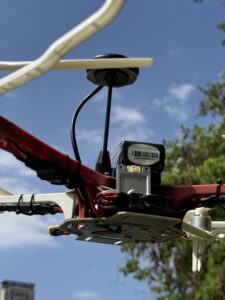
Mounting has a direct effect on inertial measurement quality. Attach the IMU to a rigid structural reference point using the specified screw mounting arrangement. Avoid flexible brackets, loose fasteners, unsupported cables, and locations close to high-amplitude structural resonances.
Document the sensor coordinate frame in the system design. The software should know which IMU axis corresponds to the robot’s forward, lateral, and vertical directions. Any intentional rotation between the sensor and machine frame should be represented in the configuration or transformation chain rather than assumed during later data processing.
Temperature and Calibration
Although HM-G12 includes full-temperature calibration from -40°C to +85°C, the complete system should still be tested in its final enclosure. Thermal gradients, nearby processors, motors, power regulators, and mounting stress can create local effects that differ from laboratory conditions.
Allow the system to reach an appropriate operating condition before collecting reference data. Test startup behavior, warm-up drift, steady-state measurements, and temperature transitions. The final evaluation should use the same power source, harness, enclosure, mounting structure, and software timing that will be used in deployment.
Arduino, Raspberry Pi, Jetson, and Custom Controllers
The product can be evaluated for Arduino-class controllers, Raspberry Pi systems, NVIDIA Jetson platforms, and custom robot computers, subject to electrical and software compatibility. Its UART interface and 3.3 V digital signal level can support many embedded architectures, but the host controller must still satisfy the required interface, voltage, connector, timing, and software requirements.
Integration work may include UART wiring, SDK guidance, ROS integration, OpenCV-based motion workflows, timestamp synchronization, data logging, coordinate-frame conversion, and application-specific configuration. Verify compatibility at the electrical, mechanical, and software levels before production deployment.
Common Measurement Errors and Limitations
Confusing Output Rate With Bandwidth
A 1000 Hz output rate does not mean that the accelerometer measures signals to 1000 Hz. HM-G12 has a stated 200 Hz accelerometer bandwidth and a stated 1000 Hz output rate. These specifications describe different parts of the signal chain. Output rate indicates how often data can be delivered, while bandwidth describes the stated response range of the sensing system.
Ignoring Mechanical Resonance
A sensor mounted on a flexible bracket may report the bracket’s resonance instead of the true machine motion. Use a rigid mounting interface and evaluate the complete mechanical assembly. Cable movement can also transfer unwanted force into a small sensor module, particularly when the cable is unsupported or routed across a moving joint.
Using an Accelerometer as a Microphone
The HM-G12 detects structure-borne acceleration. It is not a direct replacement for an air-pressure microphone. Acoustic measurement requires a sensor and frequency response intended for air-pressure signals. A mechanical accelerometer may be appropriate for casing vibration, bearing vibration, structural resonance, or transmitted machine energy, but those are different measurement objectives from airborne sound recording.
Selecting Only by Range
A ±16 g range is useful for many industrial systems, but range alone does not indicate low-vibration performance. Review bias instability, velocity random walk, bandwidth, temperature response, calibration, and axis error together.
Neglecting Cable and Power Effects
Power-supply noise, poor grounding, cable movement, electromagnetic interference, and connector problems can degrade the observed signal even when the sensor itself has strong specifications. Keep the power source within the stated input range, use an appropriate ground reference, and validate the complete electrical installation under normal machine operating conditions.
High Sensitivity Accelerometer FAQ
Can a high sensitivity accelerometer be used for acoustic measurements or as a microphone?
What specifications matter most when measuring very low vibration?
Is HM-G12 suitable for Arduino, Raspberry Pi, Jetson, or custom robot systems?
Request HM-G12 Integration Support
The Industrial High Precision IMU HM-G12 is a compact six-axis inertial sensing solution for robotics, drones, industrial automation, stabilization, and low-vibration motion measurement. With 0.016 mg accelerometer bias instability, 0.018 m/s/√h velocity random walk, a ±16 g range, 200 Hz bandwidth, full-temperature calibration, UART communication, and a 30 mm × 30 mm × 10.6 mm housing, it is designed for embedded systems that require stable inertial data in a small industrial module.
Its practical suitability should be assessed against the complete application: expected vibration, acceleration range, temperature profile, mounting structure, controller interface, coordinate frame, timing requirements, and sensor-fusion architecture. Look at those factors together. That is how engineers determine whether the HM-G12 is a good fit for a particular robot, drone, inspection platform, machine, or motion-control system.
View Product Details & Pricing ➔
📚 References & Further Reading
-
- Product Information: Industrial High Precision IMU HM-G12






