Collision Avoidance Drone Sensors: How to Choose Reliable LiDAR Vision for Safer UAV Autonomy
A collision avoidance drone is no longer just a premium consumer feature. Here’s the deal: in industrial UAV inspection, indoor mapping, mining, emergency response, research, and autonomous patrol missions, obstacle detection can be the difference between a clean data run and a broken aircraft on the floor. GPS can drift, pilots can lose line of sight, lighting can change in a hurry, and thin structures like cables, beams, poles, branches, or scaffolding can show up faster than a human operator can react. For UAV developers, the real challenge is not simply adding “a sensor.” It is choosing a perception system that gives reliable depth information while still fitting the drone’s payload, power, speed, and integration limits.
This guide walks through how collision avoidance drone sensors work, how LiDAR vision compares with stereo cameras, ultrasonic sensors, radar, and optical flow, and how to choose a reliable depth module for safer UAV autonomy. We will break down the specs that actually matter in the field: ranging distance, field of view, frame rate, accuracy, outdoor performance, weight, power consumption, and interface compatibility. We will also show where a compact solid-state dToF LiDAR such as the DTOF Solid State LiDAR HM-LD1 fits into a UAV perception stack for obstacle avoidance, altitude control, terrain following, robotic vision, and embedded development.
Table of Contents
- 👉 What Is a Collision Avoidance Drone?
- 👉 Why Collision Avoidance Matters in Industrial UAVs
- 👉 How Drone Collision Avoidance Works
- 👉 Main Sensor Types for Drone Obstacle Avoidance
- 👉 LiDAR vs Stereo Vision vs Radar vs Ultrasonic for Collision Avoidance Drones
- 👉 Key Specifications to Compare Before Choosing a Collision Avoidance Drone Sensor
- 👉 Why dToF Solid-State LiDAR Is Useful for UAV Autonomy
- 👉 DTOF Solid State LiDAR HM-LD1 for Collision Avoidance Drone Development
- 👉 How to Integrate a Collision Avoidance Sensor into a Drone
- 👉 Industrial Use Cases for Collision Avoidance Drones
- 👉 Collision Avoidance Drone Sensor Selection Checklist
- 👉 FAQ: Collision Avoidance Drone Sensors
What Is a Collision Avoidance Drone?
A collision avoidance drone is a UAV equipped with sensors, software, and control logic that detect nearby obstacles and help prevent crashes. The system may warn the pilot, slow down the aircraft, stop movement, maintain clearance, reroute around an object, support docking, or assist fully autonomous navigation. In engineering terms, the phrase describes a complete perception-to-action chain, not just one hardware component bolted to the frame.
Collision Avoidance vs Obstacle Detection
Look, this distinction matters. Obstacle detection is the sensing stage. It answers questions such as: Is there an object ahead? How far away is it? Is it inside the drone’s flight path? Collision avoidance adds the decision-making and flight response. A LiDAR module, stereo camera, radar, or ultrasonic sensor can provide obstacle information, but the aircraft still needs algorithms that interpret that data and choose a safe reaction. A developer may use a sensor to create warning zones, minimum-distance rules, soft braking, hard stops, or autonomous path planning logic.
Assisted Flight vs Autonomous Avoidance
There are several levels of collision avoidance. A basic system may only alert the pilot when an obstacle is near. A more capable assisted-flight system may brake, hover, or limit motion in the direction of the hazard. Fully autonomous avoidance may replan the path, sidestep the object, climb or descend, and continue the mission. Industrial UAV teams should define the intended level before selecting hardware, because a warning-only aircraft has very different sensing and latency requirements than a drone expected to navigate inside a tunnel without constant pilot input.
Why “Obstacle Avoidance Drone” and “Collision Avoidance Drone” Are Often Used Together
In the UAV market, “obstacle avoidance drone” and “collision avoidance drone” are often used interchangeably. For SEO and commercial research, both terms point to the same user need: safer flight near obstacles. For system designers, though, it is useful to separate the two. Obstacle avoidance normally describes detecting and moving around objects, while collision avoidance emphasizes preventing impact. A drone can detect obstacles without reliably avoiding them if the field of view is too narrow, the data is too slow, or the flight controller does not react correctly. For teams building more advanced navigation stacks, state estimation quality is also critical. See our related guide on how to master robot state estimation.
Why Collision Avoidance Matters in Industrial UAVs
Collision avoidance reduces operational risk in difficult environments where manual piloting, GPS, or basic visual line-of-sight operation may not be enough. Consumer drones often use obstacle avoidance to make photography easier. Industrial drones need it because they fly near infrastructure, machinery, people, and mission-critical assets. A crash can damage more than the aircraft; it can interrupt work, create safety hazards, and invalidate collected inspection data.
Industrial UAV Missions Often Happen Near Obstacles
In the shop, nobody designs around perfect conditions. Industrial UAVs frequently operate around bridges, dams, tunnels, warehouses, mines, power stations, wind turbines, expressways, construction sites, storage tanks, and confined spaces. These environments contain vertical walls, beams, columns, railings, pipes, scaffolding, tree branches, cables, vehicles, and workers. In many cases, the drone must fly close enough to capture detailed images or sensor measurements, but far enough to maintain safe clearance. A collision avoidance drone sensor helps provide the depth information needed to control that clearance.
The Cost of a Drone Collision Is More Than the Drone
The direct cost of a damaged UAV may be small compared with the total mission impact. A collision can damage an expensive camera, thermal imager, gas sensor, gimbal, LiDAR scanner, or communications payload. It can cause inspection downtime, lost data, project delays, battery fires, insurance complications, or safety incidents. In asset inspection, a failed flight may require another crew mobilization. In hazardous areas, retrieving a crashed drone may put people at risk. Collision avoidance should therefore be viewed as an operational risk-control measure, not merely a convenience feature.
Why GPS Alone Cannot Prevent Collisions
GPS and GNSS can help a drone understand its global position, but they do not directly tell the aircraft that a beam, wall, cable, vehicle, or tree is two meters away. GPS can drift in urban canyons, suffer multipath near steel and concrete, fail indoors, and provide insufficient accuracy for close-range inspection. Low-altitude hazards may not appear in maps, and dynamic obstacles can move into the flight path. Industrial UAV projects often combine perception sensors with survey-grade positioning tools from providers such as South Survey, but local obstacle sensing remains essential when operating near structures.
When Collision Avoidance Becomes Mission-Critical
Collision avoidance becomes mission-critical during indoor UAV navigation, return-to-home safety near trees or buildings, autonomous docking, low-altitude terrain following, automated patrol, warehouse inventory flight, tunnel mapping, and close-range inspection. It is also important in BVLOS-related autonomy research, where the aircraft may need to respond to hazards without immediate pilot correction. In these applications, sensor choice must be matched to mission speed, obstacle size, stopping distance, field of view, and system reliability.
How Drone Collision Avoidance Works
A collision avoidance drone uses a pipeline that begins with sensing and ends with flight control. The sensor alone does not “avoid” the collision. The UAV must measure the environment, convert raw readings into usable information, combine that information with flight state, decide what action is safe, and send commands to the aircraft control system. If any link in that chain is weak, the whole system is weak.
Step 1: Sense the Environment
⚙️ The first stage is environmental sensing. LiDAR and time-of-flight sensors measure distance using light. Stereo cameras estimate depth from the disparity between two images. Radar detects objects using radio waves and can be useful in dust, fog, or rain. Ultrasonic sensors measure distance using sound waves over shorter ranges. Optical flow sensors estimate motion relative to surfaces, usually for stabilization rather than full obstacle avoidance. Each sensor type produces different data, and each has unique strengths and limitations.
Step 2: Convert Raw Data into Useful Depth Information
⚙️ Raw measurements must be processed into depth maps, point clouds, range readings, obstacle masks, confidence scores, or occupancy grids. A depth map can show distance at each pixel in a 2D grid. A point cloud can represent 3D spatial information. An obstacle mask may divide the field of view into safe and unsafe regions. Developers often set confidence thresholds to ignore invalid readings, filter noise, and focus only on the area relevant to the drone’s current direction of motion.
Step 3: Fuse Sensor Data with Flight State
⚙️ Obstacle data becomes more useful when combined with IMU measurements, barometer altitude, GNSS position, optical flow, visual odometry, SLAM, and flight controller telemetry. A depth reading has different meaning when the drone is moving forward at 1 m/s versus 8 m/s. Sensor fusion helps the drone understand not only where obstacles are, but also how quickly it is approaching them and whether it has enough space to stop, climb, descend, or turn.
Step 4: Make an Avoidance Decision
⚙️ The avoidance algorithm determines what action to take. In simple systems, the drone may stop when the nearest detected obstacle is closer than a set threshold. More advanced systems may slow down as distance decreases, maintain a fixed clearance from a wall, climb over an obstacle, descend to follow terrain, sidestep a hazard, reroute around blocked space, or return to a safe hover. The correct decision depends on mission rules, aircraft dynamics, and the confidence of the sensor data.
Step 5: Send Control Commands to the UAV
⚙️ The final stage is control. A companion computer may run ROS or ROS 2 nodes, process LiDAR data, and send MAVLink obstacle distance messages to PX4 or ArduPilot. Some systems use flight controller serial interfaces, while others use Ethernet, USB, or dedicated embedded buses. A robust architecture must include fallback behavior. If the sensor loses confidence, the drone may slow, hover, alert the operator, or switch to manual control instead of continuing blindly.
Main Sensor Types for Drone Obstacle Avoidance
There is no universal sensor for every collision avoidance drone. The best option depends on range, lighting, weather, obstacle type, speed, weight, power, software complexity, and budget. Most industrial UAV developers compare LiDAR, stereo vision, monocular AI cameras, ultrasonic sensors, radar, and optical flow before selecting a final architecture.
LiDAR Sensors
✅ LiDAR measures distance using emitted light and return timing or phase information. Solid-state LiDAR and direct time-of-flight modules are attractive for UAVs because they can deliver real depth data without large rotating mechanisms. Their strengths include direct distance measurement, useful performance across many lighting conditions, point cloud output, and suitability for obstacle detection, altitude hold, and mapping support. Limitations include sensitivity to target reflectivity, bright sunlight, rain, fog, dust, and field-of-view constraints. For broader LiDAR technology context, companies such as SOS LAB demonstrate how solid-state LiDAR is becoming important across mobility and robotics markets.
Stereo Vision Cameras
✅ Stereo vision uses two cameras to estimate depth from image disparity. It can provide rich visual context and supports navigation, SLAM, and object recognition. However, stereo systems need texture, lighting, calibration, and computing resources. Low-texture walls, repetitive patterns, glare, low light, smoke, and fast motion can reduce depth quality. Stereo vision can be powerful, but it is not always the easiest path for small drones that need simple, direct range data.
Monocular Vision and AI Cameras
✅ Monocular cameras and AI vision systems are useful for detecting objects, classifying hazards, reading signs, recognizing landing pads, or supporting inspection analytics. However, detecting that an object exists does not always provide accurate distance. Monocular depth estimation often relies on learned models, assumptions, or motion. For collision avoidance, semantic awareness is helpful, but direct distance measurement is often safer and easier to validate.
Ultrasonic Sensors
✅ Ultrasonic sensors are low cost and simple. They can be effective for short-range landing assist or basic altitude measurement over certain surfaces. Their disadvantages include short range, wide acoustic beams, low spatial resolution, and weaker performance on angled, soft, irregular, or absorbing materials. They are usually not robust enough as the primary sensor for faster or more complex industrial drone obstacle avoidance.
Millimeter-Wave Radar
✅ Millimeter-wave radar can operate in poor lighting, dust, fog, rain, and some harsh industrial environments. It can detect motion and provide longer-range awareness, but it generally has lower spatial resolution than LiDAR or vision. Radar can be a strong addition to a multi-sensor system, especially when environmental conditions challenge optical sensors. It is often used as a complementary safety layer rather than a direct replacement for dense depth sensing.
Optical Flow Sensors
✅ Optical flow sensors estimate motion relative to the ground or nearby surfaces. They are valuable for indoor stabilization, velocity estimation, and position hold when GNSS is unavailable. However, optical flow is not a complete obstacle avoidance solution. It does not provide a full 3D understanding of hazards ahead, above, behind, or to the side. It is best used as part of a broader flight control and perception system.
LiDAR vs Stereo Vision vs Radar vs Ultrasonic for Collision Avoidance Drones
Choosing between LiDAR, stereo vision, radar, ultrasonic, and optical flow requires practical comparison. A collision avoidance drone should be evaluated based on mission conditions, not marketing claims. The table below summarizes common strengths, limitations, and UAV use cases.
| Sensor Type | Best For | Strengths | Limitations | Typical UAV Use |
|---|---|---|---|---|
| Solid-State LiDAR / dToF | Depth sensing, obstacle detection, point clouds | Direct distance measurement, compact modules, useful in varied lighting | Range can vary with sunlight and surface reflectivity | Obstacle avoidance, terrain following, altitude hold, mapping support |
| Stereo Vision | Visual navigation and depth in textured scenes | Rich image data, wide availability | Needs texture and light; compute-heavy | SLAM, navigation, object recognition |
| Ultrasonic | Short-range distance sensing | Low cost, simple integration | Short range, wide beam, weak on angled/soft surfaces | Landing assist, simple proximity detection |
| Radar | Harsh weather and dust | Works in fog, dust, rain; can detect motion | Lower spatial resolution | Longer-range awareness, industrial UAV safety |
| Optical Flow | Position hold and movement estimation | Lightweight and useful indoors | Not a full obstacle avoidance sensor | Indoor stabilization, velocity estimation |
Why Direct Depth Measurement Matters
Collision avoidance depends on knowing how far away an obstacle is, not only recognizing that something exists. A camera may detect a wall, cable tray, or forklift, but the control system must still know whether the object is close enough to require braking. Direct depth sensors such as LiDAR and time-of-flight modules simplify this problem by producing distance information that can be converted into thresholds, zones, point clouds, or occupancy grids.
Why Many Industrial Drones Use Sensor Fusion
Many industrial UAVs use sensor fusion because each sensor has weaknesses. LiDAR can provide depth, cameras provide visual context, IMUs provide motion information, GNSS provides global positioning, barometers support altitude estimation, and radar can improve awareness in challenging weather. Combining sensors can reduce blind spots and improve robustness. However, fusion also increases software complexity, calibration requirements, power use, and validation workload.
Why There Is No Single Best Sensor for Every Drone
The best sensor depends on mission distance, flight speed, payload limit, lighting, object size, operating environment, compute budget, and autonomy level. A compact inspection drone flying slowly indoors may prioritize weight, low power, and short-to-medium range. A long-range outdoor UAV may require greater detection distance and multi-directional sensing. A warehouse drone may need GNSS-denied navigation and close-range obstacle avoidance. A tunnel drone may require performance in darkness, dust, and confined geometry.
Key Specifications to Compare Before Choosing a Collision Avoidance Drone Sensor
Industrial buyers should compare sensor specifications through the lens of flight safety and integration effort. A specification that looks impressive on paper may not be useful if it does not match the aircraft’s speed, processor, mounting position, and environment. Look at the whole operating envelope, not just the headline number on a product page.
Ranging Capability
⚙️ Ranging capability defines the distance over which the sensor can measure objects. Indoor and nighttime performance may differ from outdoor daytime performance because sunlight adds optical noise and reduces signal quality. Reflectivity, rain, fog, dust, target angle, black surfaces, transparent materials, and glossy metal can also affect results. Developers should validate the actual usable range in the target environment, not only rely on nominal maximum range.
Ranging Accuracy
⚙️ Centimeter-level accuracy matters when the drone must maintain clearance from walls, shelves, structural surfaces, docking stations, or uneven ground. Accurate depth data can improve altitude hold, terrain following, and approach control. However, accuracy should be interpreted together with frame rate, latency, field of view, and algorithm filtering. A highly accurate single distance reading may still be insufficient for wide-area obstacle detection.
Field of View
⚙️ Field of view defines the angular area covered by the sensor. A wider horizontal FOV helps detect obstacles across the drone’s forward path, while a useful vertical FOV helps identify obstacles above or below the central line. Wider coverage can improve awareness, but point density must still be sufficient. A sensor with wide FOV and low resolution may miss small or thin objects unless the drone moves slowly, uses multiple sensors, or applies specialized detection logic.
Resolution and Point Density
⚙️ Resolution determines how many depth points are available. A depth module with a 40 × 30 grid provides 1,200 depth samples per frame. This can be enough for proximity zones, obstacle masks, and lightweight perception, but it should be evaluated against the size of expected obstacles. Thin wires, branches, cables, and poles can be difficult for many systems. Mounting angle, filtering, and redundant sensing can improve practical detection.
Frame Rate and Flight Speed
⚙️ Frame rate affects how often the system receives updated depth information. Faster drones need more frequent sensing, lower latency, and longer detection range because the aircraft covers more distance between frames. A 10fps depth sensor can support controlled low-speed autonomy if stopping distance and control latency are properly validated. Developers should test at the maximum mission speed and include worst-case braking behavior.
Weight and Size
⚙️ Weight is critical on drones because every gram affects endurance, payload capacity, center of gravity, and vibration response. Compact sensors are easier to mount on small airframes, protective housings, gimbals, or embedded robotics platforms. Mechanical design should avoid propeller obstruction, reduce vibration, protect the optical window, and preserve airflow. Weight and size also affect whether multiple sensors can be deployed for side, rear, downward, or upward coverage.
Power Consumption
⚙️ Power consumption affects battery life and thermal design. A low-power sensor reduces load on the UAV power system and allows more energy for propulsion, compute, and payloads. Developers should consider peak power, voltage regulation, electromagnetic compatibility, heat dissipation, and how sensor power is managed during startup, landing, and failsafe modes.
Interface Compatibility
⚙️ Interface compatibility can decide how quickly a project moves from prototype to flight testing. UART is common for embedded controller communication. UDP is useful for network-based streaming to companion computers. UVC can simplify early development because the sensor can behave like a camera-class device on compatible systems. Developers should also consider USB, Ethernet, CSI, SDK support, data format, timestamping, and ROS integration.
Environmental Adaptability and Software Support
⚙️ Industrial environments can include temperature extremes, vibration, dust, sunlight, reflective surfaces, electromagnetic interference, and mechanical shock. Operating temperature, housing design, filtering algorithms, and SDK support all matter. Software support for x86 Windows, x86 Linux, and ARM Linux can reduce development time across PCs, Raspberry Pi, Jetson-class systems, and embedded platforms. If your UAV platform combines perception with positioning or navigation modules, you may also be interested in our company background and engineering capabilities on the About Us page.
Need Help Choosing a UAV LiDAR Sensor?
For lightweight obstacle detection, altitude hold, terrain following, and robotic vision development, review the HM-LD1 dToF LiDAR module and compare its range, weight, power, FOV, and SDK support against your drone mission profile.
Why dToF Solid-State LiDAR Is Useful for UAV Autonomy
Direct time-of-flight solid-state LiDAR is valuable for UAV autonomy because it offers a practical balance between real depth measurement, compact packaging, and embedded integration. It can help developers create perception systems without relying only on camera texture or GPS position. That is a big advantage when the aircraft is flying close to real-world structures instead of an ideal lab target.
What Is dToF?
dToF means direct time-of-flight. The sensor emits light, measures the time it takes for that light to travel to an object and return, and calculates distance from the travel time. Because distance is measured directly, dToF sensors are useful for real-time depth maps, ranging, proximity detection, and point cloud generation. This makes them practical for UAV collision avoidance, robotic navigation, smart inspection, and embedded perception development.
What Makes Solid-State LiDAR Attractive for Drones?
Solid-state LiDAR is attractive because it avoids bulky rotating mechanisms. That can reduce mechanical wear, simplify mounting, lower weight, and improve suitability for small UAVs and robots. A compact module can be installed forward-facing for obstacle detection, downward-facing for altitude sensing, or side-facing for narrow passages. For UAVs where weight affects flight distance, a lightweight sensor can be the difference between a practical design and an overloaded airframe.
Depth Map vs Point Cloud Output
A depth map is a 2D grid where each pixel represents distance. It is useful for thresholding, obstacle masks, region-of-interest detection, and camera-like processing. A point cloud represents measured points in 3D space and can support mapping, navigation, visualization, and spatial reasoning. A collision avoidance drone may use a depth map for fast proximity decisions and a point cloud for higher-level perception or debugging.
Where dToF LiDAR Fits in a UAV Perception Stack
dToF LiDAR can support forward-facing obstacle detection, downward altitude sensing, terrain following, side obstacle awareness, indoor flight assistance, docking, landing, and approach control. It can also assist robotic vision development when developers need depth data but do not want to build a full stereo vision system. For industrial inspection, dToF LiDAR can help maintain distance from structures while cameras or gimbals capture visual data.
Limitations Developers Still Need to Validate
No sensor should be treated as crash-proof. Bright outdoor sunlight can reduce effective range, and black, glossy, transparent, or reflective surfaces may affect readings. Thin wires and cables are challenging for many perception systems. Rain, fog, dust, vibration, and mounting contamination can also degrade performance. Developers should conduct field tests with real obstacles, real speeds, and real lighting before trusting autonomous behavior.
DTOF Solid State LiDAR HM-LD1 for Collision Avoidance Drone Development
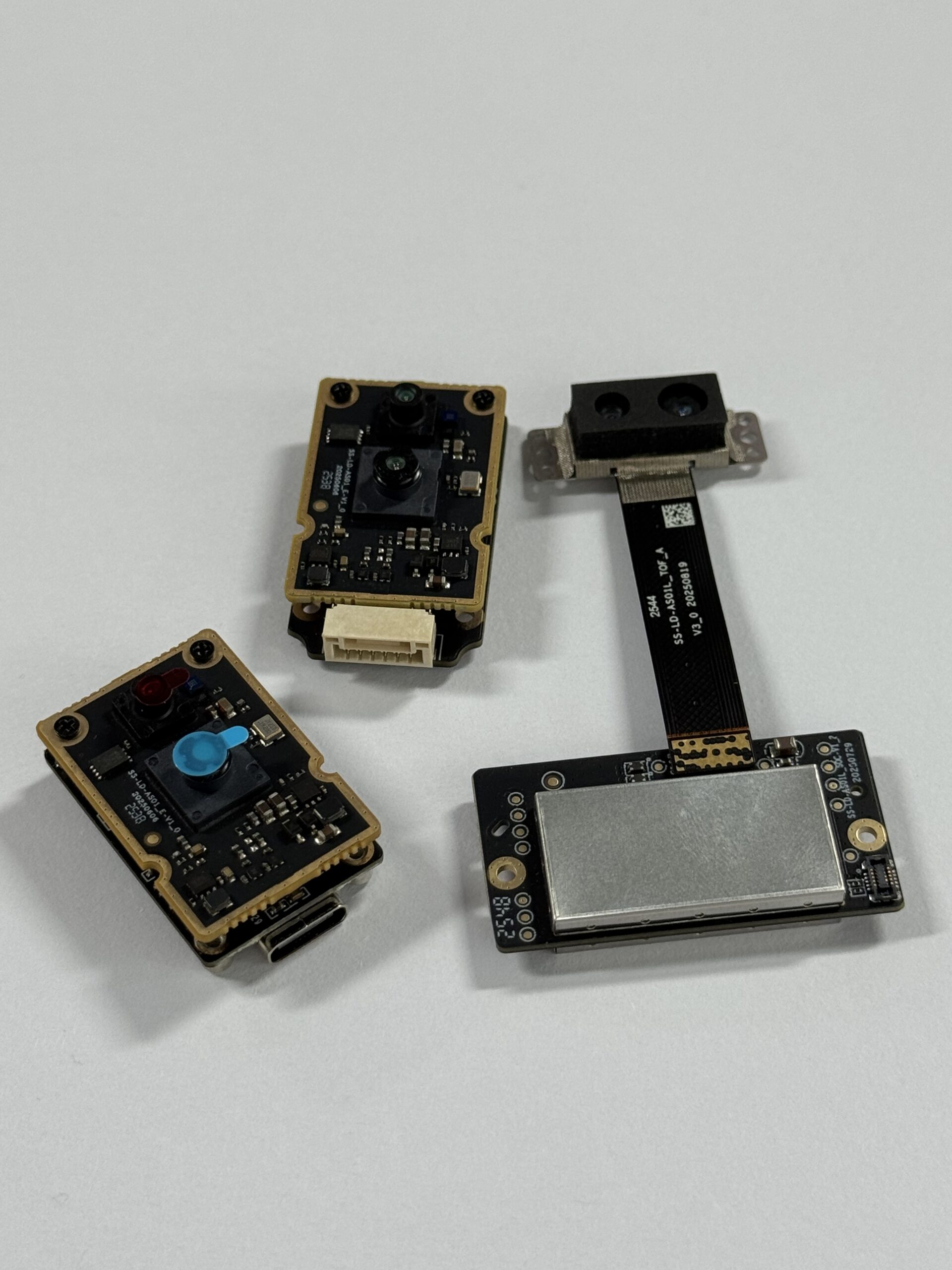
The DTOF Solid State LiDAR HM-LD1 is a compact SPAD dToF LiDAR module designed to provide real-time depth images and 3D point cloud data for environmental perception. For UAV developers, the combination of lightweight construction, low power consumption, multiple interfaces, and SDK support makes it suitable for prototyping and system deployment in drone obstacle avoidance, distance detection, altitude hold, terrain following, robotic navigation, and smart inspection applications.
Product URL: DTOF Solid State LiDAR HM-LD1
Brochure Download: DTOF SSL HM-LD1 Product Brochure

View Product Details & Pricing ➔
HM-LD1 Core Specifications and UAV Relevance
| Specification | DTOF Solid State LiDAR HM-LD1 | Why It Matters for Collision Avoidance Drones |
|---|---|---|
| Dimension | 43.5mm × 30mm × 26.5mm | Compact size helps UAV developers mount the sensor on small airframes, gimbals, protective housings, or embedded robotic platforms. |
| Ranging Capability | Indoor: 0.5–25m; Outdoor: 0.2–8m | Supports close-range obstacle detection indoors and practical outdoor distance sensing for low-speed inspection, approach, docking, and safety assistance. |
| Ranging Accuracy | ±3cm | Centimeter-level accuracy helps improve distance estimation for obstacle clearance, altitude hold, and terrain-following behavior. |
| FOV | 60° horizontal × 45° vertical | A wide field of view helps detect obstacles across a useful frontal or downward sensing area instead of a single narrow beam. |
| Weight | 28g | Low weight is important for UAV flight time, payload budget, center-of-gravity control, and integration on compact drones. |
| Resolution | 40 × 30 | Provides a depth image grid that can be converted into obstacle regions, point clouds, or proximity zones. |
| Frame Rate | 10fps | Real-time depth output supports low-speed and controlled UAV autonomy where detection latency and braking distance are properly validated. |
| Interface | UART / UDP / UVC | Multiple interfaces make integration easier with PCs, Raspberry Pi, embedded Linux systems, flight controllers, and companion computers. |
| Operating Temperature | -20℃ to 60℃ | Supports deployment in varied industrial environments, including cold storage, outdoor inspection, warehouses, and field robotics. |
| Power Consumption | 1.2W | Low power demand helps preserve UAV battery life and simplifies embedded power design. |
| SDK Support | x86 Windows, x86 Linux, ARM Linux | SDK availability reduces development time for prototype and deployment platforms including Raspberry Pi, Jetson-class systems, and Linux-based robotics stacks. |
Original Product Detail Summary
| Item | Value |
|---|---|
| Resolution | 40*30 |
| Frame Rate | 10fps |
| Interface | UART/UDP/UVC |
| Operating Temperature | -20 ℃ – 60 ℃ |
| Power Consumption | 1.2 W |
The HM-LD1 provides an example of ranging measurement data displayed as point cloud and depth data. Its ranging measurement is designed for high accuracy, including outdoor measurement at distances up to 8 meters on a clear summer day under strong light conditions, assuming approximately 80,000 lux. This outdoor measurement capability makes it useful for objects that may be difficult for people to approach, such as bridges, expressways, and dams. Its compact and lightweight housing also makes it easier to integrate into autonomous mobile robots with limited sensor space and drones where payload weight affects flight distance.
HM-LD1 is based on SPAD dToF technology and delivers real-time depth images and 3D point cloud data for accurate environmental perception. It supports 0–25m ranging in indoor or nighttime conditions and 0–8m in outdoor daytime environments, making it suitable for obstacle avoidance, distance detection, autonomous navigation, smart inspection, and robotic vision development. With UVC, UDP, and UART interfaces, HM-LD1 can be integrated with PCs, Raspberry Pi, flight controllers, and embedded platforms for both prototyping and system deployment.
Recommended UAV Integration Scenarios for HM-LD1
Recommended UAV integration scenarios include forward-facing obstacle detection, downward altitude hold, indoor flight assistance, terrain following, smart inspection, robotic vision development, UAV docking, approach assistance, and distance detection for inspection payloads. The module can also support non-UAV robotics, cameras, security systems, autofocus, user presence detection, object recognition, volume measurement, and zone intrusion monitoring when the application requires compact depth sensing.
When to Use Multiple Sensors on a Collision Avoidance Drone
One HM-LD1 can provide useful perception in the direction it faces, but one sensor cannot cover every direction of flight. A drone that moves forward, backward, sideways, upward, and downward may require multiple sensing zones. Industrial UAVs may use one front LiDAR for forward flight, one downward LiDAR for altitude hold, side sensors for narrow passages, camera and LiDAR fusion for semantic awareness, and radar for harsh environments. The correct architecture depends on mission risk and movement envelope.
How to Integrate a Collision Avoidance Sensor into a Drone
Sensor integration should follow a structured engineering workflow. The goal is not only to connect hardware, but to prove that the drone can detect relevant obstacles early enough to respond safely. Here’s the deal: a bench demo is not a flight-ready safety system. You need to test the sensor, the software, the flight controller response, and the aircraft behavior as one complete system.
Step 1: Define the Mission Profile
⚙️ Start by defining whether the drone flies indoors, outdoors, or both. Identify maximum mission speed, obstacle type, required stopping distance, lighting conditions, payload capacity, autonomy level, and safety fallback behavior. A slow indoor inspection drone has different requirements than a fast outdoor aircraft.
Step 2: Select the Sensor Mounting Position
⚙️ Mounting position determines what the drone can see. A forward-facing mount supports forward flight, a downward-facing mount supports altitude hold and terrain following, and side-facing mounts help in narrow passages. Avoid propeller obstruction, excessive vibration, lens contamination, poor airflow, and center-of-gravity imbalance. Protective windows should not degrade sensor performance.
Step 3: Connect the Interface
⚙️ Choose the data interface according to the architecture. UART can serve embedded controller communication. UDP can stream depth data over a network to a companion computer. UVC can simplify rapid prototyping with PC or embedded Linux environments. The HM-LD1 supports UART, UDP, and UVC, which gives developers flexibility across test benches, robotics platforms, and UAV systems.
Step 4: Process Depth Data
⚙️ Depth data processing may include thresholding, point cloud filtering, region-of-interest selection, noise filtering, invalid point handling, obstacle mask creation, and minimum-distance zones. Developers should account for missed readings and false returns. Obstacle zones should be mapped to the drone’s movement direction, not just displayed visually.
Step 5: Connect to the Flight Control Stack
⚙️ A companion computer may process data and send commands to the flight controller. Common architectures use ROS or ROS 2 nodes, MAVLink messages, PX4, ArduPilot, or custom embedded code. The system should define what happens when an obstacle is detected and what happens when the sensor data becomes unavailable or unreliable.
Step 6: Validate in Controlled Tests Before Autonomous Flight
⚙️ Validation should include bench testing, static obstacle testing, slow-speed flight, multiple materials, bright sunlight, dark surfaces, reflective surfaces, emergency stop behavior, and different approach angles. Developers should test the full chain: sensing, processing, decision logic, command output, and physical aircraft response. Need help selecting or integrating a perception module for your UAV platform? Contact our engineering team through My Robot Project for product guidance, SDK support, and application-specific recommendations.
Industrial Use Cases for Collision Avoidance Drones
Bridge, Expressway, and Dam Inspection
✅ Inspection drones often fly close to concrete, steel, cables, rails, and structural surfaces. Collision avoidance sensors help maintain distance while the aircraft captures images or measurements. For structures that are difficult or dangerous for people to approach, compact LiDAR depth sensing can support safer low-speed inspection workflows.
Indoor Warehouse and Factory Flight
✅ Warehouses and factories are GPS-denied environments with shelves, beams, workers, forklifts, narrow aisles, machinery, and overhead structures. A collision avoidance drone can support inventory scanning, facility monitoring, and internal inspection when local sensing is combined with stable flight control and carefully validated operating rules.
Mining and Tunnel Exploration
✅ Mines and tunnels may involve low light, dust, confined passages, uneven surfaces, and limited communications. GPS is often unavailable, so drones need onboard perception to avoid walls, ceilings, equipment, and irregular terrain. LiDAR, radar, cameras, and IMUs may be combined depending on dust level and mapping requirements.
Powerline and Utility Inspection
✅ Powerline and utility inspection presents difficult sensing problems because thin wires can be hard to detect. No single sensor should be assumed to reliably detect every cable or branch. Developers should validate carefully and consider multi-sensor fusion, conservative flight speeds, pilot supervision, and mission-specific safety margins.
Autonomous Patrol and Security
✅ Autonomous patrol drones may fly around buildings, fences, storage yards, campuses, and industrial perimeters. Collision avoidance helps reduce risk during repeated low-altitude routes. The perception system may also support zone intrusion monitoring, user presence detection, and distance measurement when integrated with cameras or security platforms.
UAV Docking, Landing, and Terrain Following
✅ Downward or forward-facing LiDAR can help drones estimate distance to landing pads, terrain, docking stations, or sloped surfaces. For aerial inspection systems that combine sensing payloads with advanced imaging, see our article on why the tri-spectral gimbal pod is a game changer. Terrain following and docking require accurate distance control, predictable latency, and robust fallback behavior.
Collision Avoidance Drone Sensor Selection Checklist
- ✅ What is the required detection range for the mission?
- ✅ Is the drone flying indoors, outdoors, or both?
- ✅ What is the maximum flight speed during obstacle detection?
- ✅ What stopping distance is required?
- ✅ Does the sensor provide real depth data or only object detection?
- ✅ Is the field of view wide enough for the flight path?
- ✅ Is the resolution sufficient for expected obstacle sizes?
- ✅ Can the sensor detect relevant surfaces under target lighting conditions?
- ✅ Is the sensor light enough for the UAV payload budget?
- ✅ Is power consumption acceptable for the battery system?
- ✅ Does the interface match the flight controller or companion computer?
- ✅ Are SDKs available for the target platform?
- ✅ Can the sensor output depth maps or point clouds?
- ✅ How will invalid or noisy readings be filtered?
- ✅ What fallback behavior occurs if the sensor loses confidence?
- ✅ Has the system been tested with real obstacles, speeds, lighting, and environments?
Need a Lightweight LiDAR Module for UAV Collision Avoidance?
The DTOF Solid State LiDAR HM-LD1 provides compact dToF depth sensing, 60° × 45° FOV, 28g weight, UART/UDP/UVC interfaces, and SDK support for industrial UAV and robotics development.
FAQ: Collision Avoidance Drone Sensors
Is collision avoidance essential for a drone, or just a premium feature?
What is the cheapest effective anti-collision setup for a DIY drone?
Are drone collision avoidance systems as good as they sound in real industrial use?
Is LiDAR better than a camera for drone obstacle avoidance?
How much range does a collision avoidance drone sensor need?
Can one LiDAR sensor provide full drone collision avoidance?
What interfaces are best for integrating a LiDAR sensor into a UAV?
What are the main limitations of collision avoidance drones?
📚 References & Further Reading
- Industry Standard: South Survey | SOS LAB
- Related Guide: How to Master Robot State Estimation | Why the Tri-Spectral Gimbal Pod Is a Game Changer | DTOF Solid State LiDAR HM-LD1