

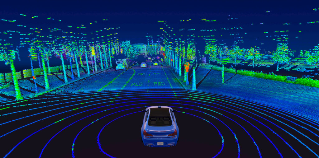
LiDAR Sensors
LiDAR Sensors for Robotics: How to Choose Compact, Accurate Depth Sensing for AMR, UAV and SLAM Applications
Robots usually do not get into trouble because they cannot move. They get into trouble because they misjudge distance. Here’s the deal: for autonomous mobile robots moving through warehouses, UAVs flying near structures, inspection robots working around bridges or dams, and SLAM systems mapping unfamiliar spaces, reliable depth perception is what separates smooth autonomy from expensive contact with the real world. Cameras can recognize objects, ultrasonic sensors can handle simple proximity checks, and radar can support longer-range awareness, but compact lidar sensors give robotics engineers something they need at the center of perception: direct, real-time distance data that can be turned into depth maps, point clouds, obstacle zones, altitude references, and localization inputs.
Choosing the right LiDAR sensor is not just a matter of picking the longest advertised range on a spec sheet. In the shop, that kind of thinking causes redesigns. Engineers have to balance field of view, frame rate, ranging accuracy, indoor and outdoor performance, power consumption, weight, interface compatibility, SDK support, and mechanical integration limits. A sensor that looks great on a bench may be too heavy for a UAV, too narrow for AMR obstacle avoidance, or too awkward to integrate into an embedded Linux platform. This guide walks through how LiDAR sensors work, how to evaluate compact dToF solid-state modules, and how to match specifications to real robotics applications such as AMR navigation, UAV altitude hold, SLAM, obstacle avoidance, terrain following, inspection, and embedded 3D sensing.
Table of Contents
- 👉 What Are LiDAR Sensors?
- 👉 How LiDAR Sensors Work
- 👉 LiDAR vs Cameras, Radar and Ultrasonic Sensors
- 👉 Key Selection Criteria for Robotics LiDAR Sensors
- 👉 Robotics Applications: AMR, UAV, SLAM and Inspection
- 👉 Why dToF Solid-State LiDAR Matters
- 👉 Product Showcase: DTOF Solid State LiDAR HM-LD1
- 👉 Integration Workflow for Embedded Developers
- 👉 Buying Checklist for Industrial Teams
- 👉 Common Mistakes When Choosing LiDAR Sensors
- 👉 Recommended Engineering Evaluation Structure
- 👉 FAQ: LiDAR Sensors for Robotics
What Are LiDAR Sensors?
LiDAR stands for light detection and ranging. In practical robotics, LiDAR sensors are depth-sensing devices that send light toward a target area and measure the returned signal to calculate distance. Depending on the sensor architecture and output format, the result may be a single distance value, a two-dimensional depth image, or a three-dimensional point cloud. For mobile robots, drones, inspection systems, smart security devices, and embedded perception platforms, this direct distance information is often more useful than a normal image alone.
Look, a LiDAR sensor is not a complete autonomy system by itself. It is a perception component that feeds distance data into a larger software and control stack. That stack may include mapping, localization, obstacle detection, path planning, motor control, safety logic, and human-machine interaction. The sensor provides physical measurements; the robot still has to decide what those measurements mean and what action to take.
a short-flex design and a long-flex design for different robotics and UAV d…
LiDAR as a Direct Depth Sensor
The main value of LiDAR is simple: it measures distance directly. A monocular camera captures visual information, but it does not inherently know whether an object is 30 centimeters away or 3 meters away. Depth can be estimated with stereo vision, visual odometry, structured light, or machine learning, but those methods depend heavily on calibration, lighting, surface texture, and algorithm design. LiDAR sensors reduce that uncertainty by measuring distance using light travel time or related optical ranging methods.
That is why LiDAR is widely used for obstacle avoidance, SLAM, localization, navigation, altitude hold, terrain following, zone monitoring, volume measurement, autofocus support, and robotic inspection. If you want a deeper foundational explanation of how LiDAR works in practical robotics systems, it helps to start with the physics of time-of-flight distance measurement and then follow how that measurement becomes usable robot perception data.
Why Compact LiDAR Sensors Are Growing in Robotics
Earlier LiDAR systems were often associated with large mechanical scanning units, vehicle-mounted mapping platforms, or high-cost autonomy systems. Those sensors still have important roles in mapping, industrial automation, and autonomous driving. Companies such as Ouster have helped expand the use of LiDAR in industrial and autonomy markets. But many modern robotics applications need something smaller, lighter, lower-power, and easier to embed.
Compact solid-state and dToF LiDAR modules are increasingly useful for AMRs, UAVs, service robots, inspection devices, smart cameras, and embedded development platforms. These applications usually have strict limits on volume, weight, power consumption, and cost. A compact LiDAR sensor can give engineers direct depth perception without forcing a major redesign of the robot body, flight platform, or electronics layout.
How LiDAR Sensors Work
Most robotics engineers start by looking at specifications such as range, accuracy, field of view, frame rate, and resolution. Those numbers matter, but they make more sense when you understand how the sensor produces distance data. In a time-of-flight system, the LiDAR emits a light pulse or controlled optical signal toward the environment. When that light reaches an object, part of it reflects back to the sensor. The receiver detects the return, and timing electronics measure how long the round trip took.
The simplified distance calculation is straightforward: distance equals the speed of light multiplied by the measured time delay, divided by two. The division by two is needed because the light travels from the sensor to the object and then back to the receiver. A shorter time delay means the object is closer; a longer delay means it is farther away. In real products, the sensor also has to deal with signal processing, ambient light, target reflectivity, optical design, calibration, and noise filtering.
Time-of-Flight Distance Measurement
Time-of-flight measurement is powerful because it gives a robot a physical distance estimate rather than only an image-based guess. In a mobile robot, this data can be used to create virtual safety zones, detect approaching obstacles, adjust speed, support docking, or feed mapping software. In a drone, time-of-flight data can help estimate altitude above surfaces, support landing awareness, and assist terrain following. For additional background, read this practical guide on how LiDAR works and how distance sensing connects to robotic perception.
In advanced autonomy markets, time-of-flight and other LiDAR architectures are also used in higher-performance systems. Companies such as Innoviz Technologies are known in the autonomy-grade LiDAR space, where long-range perception and automotive integration requirements are especially demanding. Compact robotics LiDAR sensors usually target a different design envelope: shorter to mid-range detection, small size, low power, flexible interfaces, and faster embedded development.
From Distance Pixels to Point Clouds
A single-point rangefinder provides one distance measurement. A depth sensor with multiple measurement points can provide a grid of distances. That grid is often called a depth map. A depth map works somewhat like an image, but instead of color values, each pixel-like point contains distance information. That makes it useful for detecting whether an object is inside a safety zone, whether a surface is approaching, or whether an area is open enough for movement.
A point cloud is another way to represent LiDAR data. Instead of only showing distance in a grid, a point cloud describes measured points in three-dimensional space, often using X, Y, and Z coordinates. Point clouds are useful for SLAM, mapping, structure analysis, object shape estimation, and spatial reasoning. A robot may process the same raw depth data in different ways depending on whether the goal is fast obstacle avoidance, mapping, inspection, or measurement.
Why Outdoor Performance Is Different
Outdoor LiDAR performance needs to be evaluated separately from indoor performance. Sunlight adds background optical noise, which can reduce effective range or make weak returns harder to distinguish. Target reflectivity also matters. A bright, flat, reflective surface may return a stronger signal than a dark, angled, absorbent surface. Glass, metal, wet floors, and irregular industrial backgrounds can all create measurement challenges.
That is why serious product evaluation should compare indoor and outdoor range values instead of relying on one maximum number. For example, a compact dToF module may support longer range indoors or at night and shorter range in outdoor daytime conditions. Engineers should test the sensor in the lighting, surface materials, angles, vibration levels, and motion conditions expected in the final system.
LiDAR vs Cameras, Radar and Ultrasonic Sensors
LiDAR sensors are not the only way to sense the environment. Cameras, radar, ultrasonic sensors, IMUs, encoders, and other perception devices all have important roles in robotics. The right choice depends on what the robot must know. If the robot needs semantic information, a camera is extremely useful. If it needs long-range motion detection in weather, radar may be valuable. If it only needs simple short-range proximity detection, ultrasonic sensing may be enough. If it needs direct geometric distance data, LiDAR becomes highly attractive.
| Sensor Type | Primary Strength | Common Limitation | Best Robotics Use Case |
|---|---|---|---|
| LiDAR Sensors | Direct distance, depth maps and point clouds | Performance depends on range, FOV, reflectivity and sunlight conditions | SLAM, obstacle avoidance, AMR navigation, UAV altitude hold |
| Cameras | Rich visual recognition and classification | Depth requires stereo, AI inference or visual features | Object recognition, inspection imaging, semantic perception |
| Radar | Longer-range detection and weather tolerance | Lower spatial resolution for small obstacles | Vehicle detection, long-range motion awareness |
| Ultrasonic Sensors | Low cost and simple short-range proximity detection | Limited resolution, beam spread and environmental sensitivity | Basic collision detection and parking assistance |
Why LiDAR and Cameras Are Often Used Together
LiDAR and cameras are often complementary rather than competitive. A camera can recognize a person, pallet, sign, cable, crack, label, or inspection target. LiDAR can measure how far that object is from the robot and how its geometry relates to the environment. In a warehouse AMR, the camera may help classify objects while LiDAR supports collision avoidance and spatial mapping. In an inspection platform, camera payloads can capture visual details while LiDAR provides distance and structure references.
When Ultrasonic Is Not Enough
Ultrasonic sensors are useful for simple proximity detection, especially when cost has to stay low. However, they usually provide limited spatial detail and broad beam behavior. For an AMR moving through narrow aisles, around people, or near shelves and pallets, richer depth information may be necessary. A compact LiDAR sensor can provide a more structured view of nearby space and can be integrated into higher-level perception logic.
When Radar Complements LiDAR
Radar has advantages in certain harsh weather or long-range detection scenarios. It can be valuable for vehicles, outdoor machinery, and systems that need motion awareness over longer distances. However, compact robotic platforms often still need short-to-mid-range spatial detail. LiDAR can help detect nearby obstacles, surfaces, openings, and geometry that matter for navigation and control.
Key Selection Criteria for Robotics LiDAR Sensors
Selecting LiDAR sensors for robotics requires more than comparing price and maximum range. A robot is a system of tradeoffs. The sensor has to fit the mechanical design, power budget, compute architecture, software stack, safety strategy, and operating environment. The best sensor is not always the one with the longest range; it is the one whose specifications match the perception task with enough margin for real-world variation.
Ranging Capability
Range should be evaluated by environment. Indoor or nighttime range can be longer because ambient light is lower. Outdoor daytime range may be shorter because sunlight increases optical noise and can reduce the signal-to-noise ratio. For example, the DTOF Solid State LiDAR HM-LD1 supports indoor ranging from 0.5m to 25m and outdoor ranging from 0.2m to 8m. That split is useful because it helps engineers make realistic decisions for AMRs, UAVs, and inspection robots.
Ranging Accuracy
Accuracy determines whether the robot can trust the measurement for control decisions. ±3cm accuracy can be meaningful for obstacle avoidance, docking, distance measurement, inspection positioning, and short-to-mid-range mapping. However, accuracy should always be validated under the expected lighting, reflectivity, angle, and motion conditions. A sensor may behave differently on dark rubber, bright painted metal, glass, concrete, cardboard, and wet surfaces.
Field of View
Field of view determines how much of the scene the sensor can observe. Horizontal FOV is important for AMRs because the robot must detect obstacles across its travel path and side approach zones. Vertical FOV matters for drones, terrain following, landing awareness, ramps, shelves, and multi-level obstacles. The HM-LD1 provides a 60° horizontal by 45° vertical field of view, giving compact depth coverage for embedded perception tasks.
Resolution
Resolution affects how much spatial detail the sensor can capture. A higher resolution can identify smaller features or more detailed shapes, while lower resolution may be enough for zone detection, altitude reference, or simple obstacle sensing. The HM-LD1 has a 40 × 30 resolution, which is suitable for compact depth perception, basic point cloud generation, presence detection, and embedded obstacle sensing where small size and low power are important.
Frame Rate
Frame rate determines how often the sensor updates the robot with new distance data. A faster robot generally needs more frequent updates or more conservative stopping distances. The HM-LD1 operates at 10fps. For many compact robotics applications, 10fps can support real-time perception when vehicle speed, control loop timing, filtering, and safety margins are designed appropriately.
Weight and Dimensions
Mechanical constraints are often decisive. UAVs are especially sensitive to payload weight because every gram can affect flight time and stability. AMRs, smart cameras, and embedded inspection devices may also have limited internal space. The HM-LD1 weighs 28g and measures 43.5mm × 30mm × 26.5mm, making it easier to mount inside compact robot bodies, drone payload spaces, and development prototypes.
Power Consumption
Power consumption affects battery life, heat, enclosure design, and system reliability. A 1.2W LiDAR module can be easier to integrate into battery-powered robots than a larger, higher-power sensor. Low power is especially important for UAVs, portable systems, and embedded platforms that already power processors, radios, motors, cameras, and other sensors.
Interfaces and SDK Support
Interface compatibility can save serious development time. UART is useful for embedded controllers and flight controller communication. UDP can support networked robotics systems and higher-throughput data transfer. UVC can simplify camera-style depth streaming into PC-based workflows. SDK support for x86 Windows, x86 Linux, and ARM Linux helps teams evaluate the sensor across PCs, Raspberry Pi-class systems, embedded Linux boards, and development workstations. For broader selection context, see this guide to choosing affordable portable 3D scanning for robots.
Robotics Applications: AMR, UAV, SLAM and Inspection
LiDAR sensors are valuable because they convert distance into actionable robot perception. The same compact module can support different applications depending on mounting, filtering, software, and control strategy. An AMR may use depth data to avoid pallets. A UAV may use it to maintain altitude. A security system may use it to detect presence in a defined zone. An inspection robot may use it to measure distance from a structure that is unsafe or difficult for people to approach.
AMR Obstacle Avoidance and Navigation
Autonomous mobile robots must detect walls, people, shelves, pallets, low obstacles, docking stations, and temporary objects. A LiDAR depth map or point cloud can help the navigation stack estimate free space and trigger obstacle avoidance logic. For AMRs in warehouses or factories, short-to-mid-range sensing is often more important than very long range. The robot needs reliable information within its stopping distance and maneuvering envelope.
UAV Altitude Hold and Terrain Following
UAVs need lightweight sensors that provide useful range data without consuming too much power. Compact LiDAR sensors can help drones maintain altitude above ground, follow terrain, detect landing surfaces, and improve low-altitude awareness. Weight and power are critical because they directly affect flight duration and payload capacity. For drone-based inspection, LiDAR can work alongside cameras, thermal payloads, and positioning systems. Teams developing aerial inspection workflows may also consider drone inspection platforms with thermal camera payloads when visual and thermal data are needed together.
SLAM and Localization Support
SLAM systems use sensor data to build a map and estimate the robot’s position within that map. LiDAR can contribute geometric measurements of walls, edges, obstacles, and structural features. In many systems, LiDAR data is combined with wheel odometry, IMU data, visual features, GPS, or other references. Sensor resolution, field of view, frame rate, timing synchronization, and calibration all affect SLAM quality. Compact dToF LiDAR can be useful for development platforms that need small size, low power, and practical embedded interfaces.
Smart Inspection for Bridges, Expressways and Dams
Inspection environments often include structures that are difficult or dangerous for people to approach. The HM-LD1 product details describe accurate ranging from outdoor distances up to 8 meters on a clear summer day assuming 80,000 lux. That kind of compact distance sensing can help robots or UAVs measure distance to bridges, expressways, dams, walls, and other infrastructure. The value is not only measurement; it is safer positioning, repeatable standoff distance, and more consistent data collection.
Security, Presence Detection and Zone Monitoring
LiDAR sensors can also support smart security and presence detection. A depth sensor can monitor whether a person or object enters a defined zone, estimate object position, support volume measurement, or trigger recognition workflows. Compared with passive visual sensing alone, depth data provides spatial context. This can be useful in controlled zones, service robots, smart cameras, and industrial monitoring systems.
Why dToF Solid-State LiDAR Matters
dToF stands for direct time of flight. In a dToF LiDAR system, the sensor directly measures the time it takes for emitted light to return after reflecting from a target. This differs from perception approaches that infer depth from images or depend on mechanical scanning architectures. For compact robots, dToF solid-state LiDAR offers a practical balance of direct distance measurement, small form factor, lower mechanical complexity, and embedded integration flexibility.
dToF vs Mechanical Scanning LiDAR
Mechanical scanning LiDAR systems often use moving components to sweep a laser or optical measurement across the environment. These systems can provide wide coverage and are widely used in mapping, autonomy, and industrial perception. However, moving parts, larger housings, and power requirements may be challenging for small robots and UAVs. Solid-state designs can reduce mechanical complexity and make it easier to integrate LiDAR into compact enclosures.
SPAD-Based Depth Sensing
SPAD means single-photon avalanche diode. At a high level, SPAD-based sensors can detect very low levels of returned light, supporting compact optical depth sensing. In a dToF LiDAR module, SPAD technology helps measure light returns and generate depth information. The practical benefit for engineers is a small sensor package that can output usable depth images and point cloud data for perception tasks.
Benefits for Embedded Robotics
Compact dToF solid-state LiDAR can reduce mechanical footprint, lower weight, reduce power requirements, simplify mounting, and reduce exposure to moving-part wear. It can be easier to evaluate on PCs, Raspberry Pi-class devices, Jetson-class systems, embedded Linux boards, and flight-controller-adjacent architectures when the interface and SDK support are appropriate. This is especially valuable for rapid prototyping and for teams moving from lab testing toward system deployment.
Limits Engineers Should Still Consider
Compact dToF modules are not automatic replacements for high-end long-range automotive LiDAR. Engineers still need to evaluate range, FOV, resolution, sunlight conditions, target reflectivity, safety requirements, and software integration. Larger autonomy platforms may need higher-resolution, wider-FOV, longer-range LiDAR from specialized suppliers such as Innoviz Technologies or industrial 3D perception solutions from companies such as Ouster. Compact modules serve a different need: practical depth sensing in space- and power-limited robotics systems.
Product Showcase: DTOF Solid State LiDAR HM-LD1
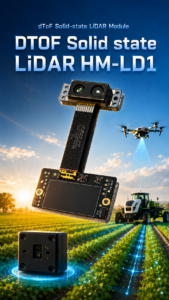
The DTOF Solid State LiDAR HM-LD1 is a compact dToF LiDAR module designed for robotics developers, UAV integrators, and embedded perception systems that need real-time depth data without adding significant size, weight, or power burden. Based on SPAD dToF technology, HM-LD1 outputs depth images and 3D point cloud data for obstacle avoidance, distance detection, autonomous navigation, smart inspection, and robotic vision development.
Its small 28g body, 60° horizontal × 45° vertical field of view, ±3cm ranging accuracy, and UART/UDP/UVC interfaces make it suitable for AMRs, drones, Raspberry Pi projects, embedded Linux systems, and PC-based development. It supports indoor or nighttime ranging up to 25m and outdoor daytime ranging up to 8m, making it useful for compact robots that need practical depth perception in both controlled and real-world environments.
View Product Details & Pricing ➔
| Specification | DTOF Solid State LiDAR HM-LD1 |
|---|---|
| Dimensions | 43.5mm × 30mm × 26.5mm |
| Ranging Capability | Indoor: 0.5–25m; Outdoor: 0.2–8m |
| Ranging Accuracy | ±3cm |
| Field of View | 60° horizontal × 45° vertical |
| Weight | 28g |
| Resolution | 40 × 30 |
| Frame Rate | 10fps |
| Interface | UART / UDP / UVC |
| Operating Temperature | -20 ℃ to 60 ℃ |
| Power Consumption | 1.2W |
| SDK Support | x86 Windows, x86 Linux and ARM Linux |
Why These Specifications Matter
The HM-LD1’s 28g weight matters for UAV payload constraints and for compact robots where sensor placement affects balance and enclosure design. Its 1.2W power consumption supports battery-powered systems and reduces thermal burden. The 60° × 45° FOV provides compact depth coverage for forward-facing, downward-facing, or application-specific mounting. The 10fps frame rate supports real-time environmental updates when the robot’s speed and safety margins are designed accordingly.
The UART, UDP, and UVC interfaces give engineers options. UART can be useful for embedded controllers. UDP can fit networked robotics systems. UVC can simplify depth streaming in PC-style computer vision workflows. SDK support for x86 Windows, x86 Linux, and ARM Linux makes the module practical for development across workstations and embedded platforms.
Best-Fit Applications
HM-LD1 is best suited for compact robotics tasks such as AMR obstacle detection, UAV altitude hold, terrain following, SLAM development, embedded depth sensing, distance measurement, inspection robotics, presence detection, zone intrusion monitoring, object recognition triggers, and volume measurement. It is especially relevant where engineers need a practical balance of range, compact size, low weight, low power, and flexible integration.
Brochure Download
Download technical brochure: DTOF SSL HM-LD1 Product Brochure
Integration Workflow for Embedded Developers
Successful LiDAR integration starts before wiring the sensor. Engineers should define the perception task, mounting location, data format, control loop, and validation environment. A LiDAR sensor is only useful when its data is aligned with the robot’s mechanical design and software decisions. The following workflow helps reduce uncertainty during prototype and production planning.
⚙️ Step 1 — Define the Perception Task
Start by identifying what the robot must accomplish. Obstacle avoidance, altitude hold, SLAM, inspection measurement, presence detection, object detection, and zone monitoring all have different requirements. A UAV looking downward for altitude hold may need different mounting and filtering than an AMR looking forward for pallets and pedestrians.
⚙️ Step 2 — Match Range and FOV to the Robot
Range must match the robot’s speed, stopping distance, and operating space. Field of view must match the obstacle zone and mounting angle. An AMR may need horizontal coverage across the travel path. A drone may need downward or angled sensing. An inspection robot may need a stable standoff distance from a wall, bridge, expressway component, or dam surface.
⚙️ Step 3 — Choose the Interface
Interface selection affects software architecture. UART is often appropriate for simpler embedded communication or controller integration. UDP can be useful when moving depth data over a networked robotics system. UVC can simplify integration into computer vision workflows because it behaves more like a camera-style stream. The best choice depends on the compute platform, data rate, operating system, and development tools.
⚙️ Step 4 — Validate Depth Data in Real Environments
Bench testing is not enough. Engineers should test indoor lighting, outdoor daylight, reflective surfaces, dark objects, angled targets, transparent or semi-reflective materials, vibration, enclosure effects, and expected robot motion. Outdoor testing is especially important because sunlight and target reflectivity can reduce usable range. The validation plan should include both raw data inspection and behavior-level testing on the robot.
⚙️ Step 5 — Connect to Robotics Software
Depth data can be processed with ROS, OpenCV, custom C++ or Python pipelines, embedded Linux applications, Raspberry Pi-class systems, or Jetson-class platforms depending on the project. If a software feature is not explicitly confirmed by product documentation, treat it as a development target rather than a guaranteed plug-and-play capability. The engineering team should confirm data format, timestamping, synchronization, filtering, and coordinate transformations before committing to a final architecture.
⚙️ Step 6 — Calibrate and Tune Safety Logic
Calibration converts sensor measurements into robot coordinates. Engineers should account for mounting offsets, tilt, vibration, enclosure windows, and timing delays. Safety logic should include filtering, confidence thresholds, obstacle zones, stopping distances, and fail-safe behavior. A sensor can detect distance, but the robot must decide how to respond when data is missing, noisy, unexpected, or outside operating limits.
Buying Checklist for Industrial Teams
Industrial LiDAR purchasing should include both engineering and procurement perspectives. Engineering teams need performance validation, integration confidence, and data quality. Procurement teams need documentation, stable supply, lead-time visibility, technical support, and customization options. A low-cost sensor can become expensive if it requires excessive integration effort or fails in the target environment.
Engineering Checklist
Engineering evaluation should include raw data quality, distance accuracy, latency, frame rate stability, mechanical mounting, optical window effects, vibration behavior, temperature range, and software compatibility. Engineers should also verify how the sensor behaves with difficult materials such as black rubber, glass, polished metal, wet concrete, and angled surfaces. The goal is not just to confirm that the sensor works; the goal is to confirm that it works reliably in the actual robot use case.
Procurement Checklist
Procurement teams should confirm product documentation, brochure availability, technical support, lead time, customization options, and stable supply. Direct manufacturing and source-factory support can matter when moving from prototype to production. If the project requires a compact dToF module, review the DTOF Solid State LiDAR HM-LD1 product page and compare its specifications against your range, interface, weight, and power requirements. For broader scanning selection, revisit the guide to choosing affordable portable 3D scanning for robots.
Common Mistakes When Choosing LiDAR Sensors
Many LiDAR selection problems come from evaluating the sensor as a standalone component instead of part of a robot system. A specification may look strong on paper but fail to match the application. Avoiding the following mistakes can save engineering time and reduce redesign risk.
Choosing Only by Maximum Range
Maximum range is important, but it is incomplete without field of view, resolution, frame rate, accuracy, and environmental context. A long-range sensor with narrow coverage may not be ideal for close obstacle avoidance. A compact sensor with moderate range may be better for a UAV altitude-hold task or an AMR safety zone.
Ignoring Outdoor Sunlight Conditions
Outdoor LiDAR range is often shorter than indoor range because sunlight creates background optical noise. Always check outdoor daytime specifications separately. If the robot operates in mixed lighting, test both bright sunlight and shadow transitions.
Overlooking Mechanical and Power Constraints
Size, weight, and wattage can be decisive in UAVs and compact robots. A sensor that is too heavy may reduce flight time. A sensor that consumes too much power may increase heat or reduce battery life. A sensor that is physically awkward may force poor mounting geometry.
Not Testing Real Target Materials
Robots encounter dark surfaces, reflective metal, glass, wet floors, angled panels, fabrics, plastics, pallets, and complex backgrounds. These materials can affect return strength and measurement reliability. Test the actual materials expected in the operating environment before final selection.
Treating LiDAR as a Complete Autonomy System
LiDAR is a sensing component. It must be integrated with perception software, planning, control, safety logic, calibration, and system validation. A good sensor improves distance awareness, but safe autonomy requires a full engineering process.
Recommended Engineering Evaluation Structure
For teams documenting LiDAR evaluation internally, it is useful to organize requirements by engineering function. This ensures that mechanical, electrical, software, perception, safety, and procurement teams evaluate the same sensor from different but coordinated perspectives.
| Evaluation Area | Recommended Review Focus |
|---|---|
| Application Definition | Obstacle avoidance, SLAM, altitude hold, inspection, presence detection or measurement |
| Optical Performance | Indoor range, outdoor range, accuracy, reflectivity behavior and sunlight tolerance |
| Spatial Coverage | Field of view, resolution, mounting angle and detection zone |
| Timing | Frame rate, latency, synchronization and control-loop compatibility |
| Mechanical Integration | Dimensions, weight, enclosure fit, vibration, optical window and cable routing |
| Electrical Integration | Power consumption, thermal behavior, interface and connector strategy |
| Software Integration | SDK support, operating system compatibility, data format and processing pipeline |
| Procurement | Documentation, technical support, stable supply, customization and production readiness |
This structure helps prevent teams from overvaluing one specification while ignoring another. A strong LiDAR choice balances performance, integration effort, and system reliability. For compact robotics, that balance often means choosing a sensor with enough range and accuracy, practical FOV, low weight, low power, and interfaces that match the development platform.
FAQ: LiDAR Sensors for Robotics
How do LiDAR sensors actually work, and why are they important for robots?
Why do engineers and self-driving developers care so much about LiDAR if cameras already exist?
Where can I find a lightweight and cost-effective LiDAR sensor for UAVs, AMRs or embedded development?
What is the difference between a LiDAR depth map and a LiDAR point cloud?
Is solid-state LiDAR better than mechanical LiDAR?
What LiDAR specifications matter most for AMR obstacle avoidance?
What LiDAR specifications matter most for UAVs?
Can LiDAR sensors be used for SLAM?
How should engineers test LiDAR sensors before production integration?
📚 References & Further Reading
- Industry Standard: Innoviz Technologies | Ouster
- Related Guide: How Does LiDAR Work? | LiDAR Scan Guide: Choosing Affordable Portable 3D Scanning for Robots | DTOF Solid State LiDAR HM-LD1






