

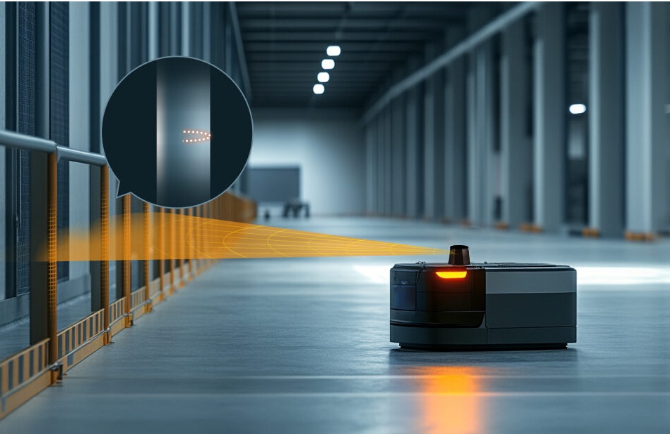
LiDAR Scan Guide: Choosing Affordable, Portable 3D Scanning for Robots, Drones, and Site Surveys
A lidar scan is not just something you see on expensive survey trucks or in a university lab anymore. Here’s the deal: the technology has moved into the hands of robotics builders, UAV teams, inspection crews, automation engineers, facility managers, security integrators, and technical buyers who need real depth data without dragging around a six-figure mapping system. These teams are looking for affordable and portable LiDAR scanning options that can produce usable distance measurements, point clouds, obstacle maps, and depth information in real working environments. The hard part is separating what looks impressive in a demo from what actually works on a robot, drone, embedded platform, smart camera, or inspection tool after it leaves the bench.
The market can get messy fast. A phone-based LiDAR scan app looks convenient. A DIY LiDAR scanner looks cheap. A handheld 3D scanner might produce a good-looking model. A survey-grade terrestrial scanner may deliver dense point clouds with serious measurement capability. A compact solid-state LiDAR module may not look flashy, but it may be exactly what an industrial system needs. Look, these are not the same tools. They may all get called “LiDAR scanning,” but they are built for different jobs, different users, different data outputs, and very different levels of engineering control.
This guide breaks down how LiDAR scanning works, what “portable” and “affordable” really mean in industrial applications, and how to compare phone LiDAR, DIY LiDAR scanners, handheld 3D scanners, survey-grade systems, and compact solid-state LiDAR modules. It is written for people who need more than marketing language. Range, accuracy, field of view, frame rate, point cloud output, interface support, SDK availability, mounting constraints, power consumption, and environmental adaptability all matter when the sensor has to work in the real world. In the shop, on a drone frame, inside a robot chassis, or mounted to a smart inspection device, those details decide whether the project moves forward or turns into a wiring-and-software headache.
We will also highlight the DTOF Solid State LiDAR HM-LD1 as a compact dToF solid-state LiDAR option for robotic vision, UAV altitude sensing, obstacle avoidance, smart inspection, and embedded 3D perception projects. The goal is not to pretend one sensor solves every problem. The goal is to help you choose the right class of LiDAR scan solution for the job, then understand where a compact module like HM-LD1 fits.
Full LiDAR setups are powerful — but often too heavy, too complex, or just …
Table of Contents
- 👉 What Is a LiDAR Scan?
- 👉 How LiDAR Scanning Works
- 👉 Main Types of LiDAR Scanning Solutions
- 👉 Phone LiDAR vs Industrial LiDAR Modules
- 👉 How to Choose an Affordable Portable LiDAR Scanner
- 👉 Robots, Drones, and Site Survey Use Cases
- 👉 Technical Buying Criteria That Matter
- 👉 DTOF Solid State LiDAR HM-LD1 Product Specs
- 👉 Integration Workflow for Developers
- 👉 Common Mistakes to Avoid
- 👉 LiDAR Scan FAQ
What Is a LiDAR Scan?
A LiDAR scan is the process of using light-based distance measurement to capture spatial information about objects, rooms, terrain, structures, vehicles, people, machinery, or dynamic work areas. LiDAR stands for Light Detection and Ranging. In plain shop-floor language, the system sends out light, waits for the reflection, measures the return, calculates distance, and turns many of those measurements into data that software or people can use. Depending on the hardware and software pipeline, the output may be a single distance reading, a depth map, a LiDAR point cloud, an occupancy map, a 3D LiDAR scan, or a reconstructed mesh.
For readers who want broader context on optical sensing technologies, the IEEE Photonics Society provides educational resources on photonics and light-based engineering. That matters because LiDAR performance is not magic and it is not only software. It depends on optical design, signal detection, timing precision, photon sensitivity, ambient light rejection, surface reflectivity, and how reliably the system can separate a real return from noise. A polished demo in a controlled room is one thing. Stable measurement beside a vibrating robot, under a skylight, or near reflective metal is another.
A common misunderstanding is that every lidar scan must create a photorealistic 3D model. That is true for some consumer scanning workflows, but it is not the whole story. A robot may not care about a pretty mesh of a room. It may need a reliable depth frame every fraction of a second so it can avoid a person, pallet, wall, shelf, ramp, cable tray, or overhanging object. A drone may not need a textured model of a building. It may need altitude data, terrain-following information, or forward obstacle detection. A security system may not need color imagery at all; it may only need depth-based zone monitoring that works in low light.
This difference is a big deal when comparing a portable LiDAR scanner, an iPhone LiDAR scan app, a handheld scanner, a DIY LiDAR scanner, and a compact robot LiDAR sensor. Consumer tools usually prioritize convenience, visual reconstruction, and easy exports. Industrial LiDAR modules usually prioritize range, repeatability, latency, interface options, SDK support, power consumption, mechanical integration, and machine-readable data. Neither path is automatically better. The right choice depends on the task, the required output, the environment, and whether the scan will be interpreted by a person or used by a real-time control system.
How LiDAR Scanning Works
Time-of-Flight Distance Measurement
Many modern LiDAR systems calculate distance by measuring how long it takes for emitted light to return after reflecting from a surface. This is commonly called time-of-flight measurement. In a direct time-of-flight, or dToF, system, the sensor measures the travel time of light pulses directly. The basic process is simple enough: the emitter sends light toward the scene, the light reflects from an object surface, the receiver detects the returning signal, and the system calculates distance from the measured travel time. Because the light travels out and back, the measured travel distance is divided by two when calculating object distance.
In real hardware, the challenge is not understanding the concept. The challenge is doing it precisely. Light moves extremely fast, so the system has to detect very small timing differences. Performance also depends on target reflectivity, ambient light, surface angle, optical filtering, receiver sensitivity, signal processing, and the ability to reject false or weak returns. Solid-state dToF LiDAR modules use compact optical and electronic designs to produce depth information without relying on a large spinning mechanical assembly. That is why they are attractive for robots, drones, smart cameras, embedded platforms, and tight industrial devices where space and reliability matter.
Depth Maps, Point Clouds, and Meshes
A depth map is a two-dimensional grid where each pixel or cell contains distance information. For robotics and automation, this can be extremely useful because software can identify nearby obstacles, estimate open space, define warning zones, or determine whether an object has entered a monitored area. A LiDAR point cloud is a collection of points in three-dimensional space. Each point usually represents a measured location on a visible surface, and point cloud data may be used for mapping, SLAM, object detection, volume measurement, inspection, or spatial analysis. A mesh is different. It is a connected surface model used for visualization, 3D reconstruction, AR, architecture, or digital documentation.
The output format should match the application. A facility manager documenting room layouts may prefer a mesh or registered point cloud. A mobile robot may prefer a stream of depth images or point cloud frames. A UAV altitude-hold system may only need reliable distance and terrain information. An industrial inspection device may need both raw depth output and processed measurement zones. Choosing a LiDAR scan solution without defining the output format is how teams overbuy, underperform, or end up writing software they did not budget for.
Resolution, Frame Rate, and Field of View
Resolution determines how many depth samples are captured in each frame. Frame rate determines how often the sensor updates. Field of view determines how much of the scene the sensor can observe from a fixed mounting position. These three specifications work together. Higher resolution may provide more spatial detail, but it can increase data bandwidth, processor load, memory use, power consumption, and cost. A wider field of view may cover more area, but it may spread measurements across a broader angle. A faster frame rate can improve responsiveness, but only if the data is stable and usable.
For a compact robot or UAV, the best LiDAR scanner is not always the highest-resolution model. A lower-resolution depth sensor can still be the right tool if it provides repeatable distance data, enough field of view for the task, manageable power consumption, and interfaces that work with the target controller or computer. In machine perception, usable data at the right time often beats impressive-looking scans delivered too slowly or in the wrong format.
Solid-State LiDAR vs Mechanical LiDAR
Mechanical LiDAR systems often use rotating or moving components to scan a wider area. They can be effective for mapping, navigation, and survey applications, but they may be larger, heavier, more expensive, or more mechanically complex. Solid-state LiDAR avoids a large spinning assembly and is often better suited for compact embedded systems. A solid-state dToF module can be mounted into a robot, UAV, smart inspection device, camera system, or industrial sensing node where size, weight, durability, power, and integration time are all part of the design review.
Main Types of LiDAR Scanning Solutions
Smartphone LiDAR Scans
Smartphone LiDAR scanning is popular because it is convenient. Selected iPhone and iPad Pro models can support LiDAR scan apps for quick room capture, AR measurement, rough layout documentation, furniture planning, and basic 3D visualization. For non-critical tasks, this can be very useful. A user can walk through a room, generate a rough model, and share an export without buying a separate scanner.
But a phone is not an industrial sensor module. It is not designed to be permanently mounted on a robot, drone, access control system, smart camera, or inspection device. It may have limited usable range, app-dependent processing, inconsistent exports, limited raw sensor access, and less predictable timing control. For early concept communication, an iPhone LiDAR scan can be excellent. For continuous machine perception, it is usually not the engineering path you want to build a product around.
Handheld 3D LiDAR or Structured-Light Scanners
Handheld 3D scanners are often used for objects, rooms, reverse engineering, asset documentation, cultural heritage, design workflows, and visual inspection. Some use LiDAR, while others use structured light, photogrammetry, or hybrid sensing. These scanners can produce impressive 3D models, but they often require manual operation, controlled scanning technique, registration software, and post-processing. They are usually optimized for reconstructed models rather than real-time embedded control.
If the goal is to scan a part for documentation, a handheld 3D scanner may be a good choice. If the goal is to give a mobile robot real-time obstacle awareness, a handheld scanner is usually the wrong form factor. The data pipeline, mounting approach, power strategy, timing behavior, and integration requirements are completely different.
DIY and Open-Source LiDAR Scanners
DIY and open-source LiDAR scanners are excellent for learning and prototyping. Developers may combine a low-cost distance sensor with a rotating mount, a microcontroller, a single-board computer, and open-source mapping software. This teaches the whole system: sensing, calibration, data acquisition, synchronization, filtering, mapping, and visualization. It can be a valuable path for students, makers, research teams, and early-stage experiments.
The limitation is deployment risk. Mechanical wobble, vibration, calibration drift, temperature changes, sunlight, dust, reflective surfaces, and software maintenance can all reduce reliability. A DIY LiDAR scanner that works well on a bench may not survive a mobile robot, UAV, warehouse, construction site, or outdoor inspection route. For customer-facing systems, a purpose-built industrial LiDAR module with documented specifications and support is often a more efficient and lower-risk choice.
Compact Industrial LiDAR Modules
Compact industrial LiDAR modules are designed for integration. They are often used in robots, UAVs, smart cameras, access control systems, inspection devices, embedded AI systems, and automation equipment. Instead of focusing only on visual reconstruction, these modules usually provide stable interfaces, repeatable data output, SDK support, and mechanical characteristics that engineers can design around. Common interface options may include UART, UDP, UVC, CAN, USB, or Ethernet depending on the product.
This category is especially relevant when a buyer searches for an affordable portable LiDAR scanner but actually needs a sensor module. The module may not look like a handheld scanner, but it may be far more useful for a robot, drone, or industrial product because it can be mounted, powered, and integrated into a real system.
Survey-Grade Terrestrial LiDAR Scanners
Survey-grade terrestrial LiDAR scanners are used for construction, BIM, mining, infrastructure, forensics, civil engineering, geospatial mapping, and high-accuracy documentation. They can deliver long range and dense point clouds, but they are typically expensive and not intended for small embedded platforms. They may require tripods, survey workflows, registration software, trained operators, and specialized deliverables. For certified measurements and large-scale site surveys, they may be necessary. For compact robotics and UAV obstacle sensing, they are usually too large, heavy, costly, or workflow-intensive.
Phone LiDAR vs Industrial LiDAR Modules
Where Phone LiDAR Works Well
Phone LiDAR works well when speed and convenience are more important than engineering control. It can help with room layout capture, quick measurements, furniture placement, AR visualization, and informal documentation. It is useful for early conversations because a user can produce a rough 3D view quickly. It is also accessible because many users already own a compatible device.
Where Phone LiDAR Starts to Fail
Phone LiDAR starts to fail when the application requires repeatability, raw data control, known timing, stable mounting, industrial power management, environmental testing, or embedded integration. A phone is a complete consumer device, not a sensor component. It is difficult to mount permanently, difficult to synchronize with other robot sensors, and difficult to guarantee as part of a product design. Apps may change, operating systems may update, export formats may be limited, and the scanning result may depend heavily on how the operator moves through the scene.
Why Industrial Modules Are Better for Robots and Drones
Industrial LiDAR modules are usually better for robots and drones because they are built as components. Engineers can define a mounting position, connect a power rail, use a supported interface, process depth or point cloud data, and design repeatable behavior. Interface options such as UART, UDP, and UVC can support embedded controllers, PCs, Raspberry Pi-class systems, flight controllers, and Linux-based platforms. SDK availability can reduce development time and make it easier to test, log, and process sensor output.
Instead of treating a phone as a scanner, industrial teams often choose a compact dToF LiDAR module that can be mounted directly on a robot, UAV, smart inspection device, or embedded test platform. The DTOF Solid State LiDAR HM-LD1 is an example of this approach, offering compact solid-state depth sensing for machine perception applications.
View Product Details & Pricing ➔
How to Choose an Affordable Portable LiDAR Scanner
Define the Output You Actually Need
Before comparing price, define the output. Do you need simple distance readings, a depth map, a point cloud, a 3D mesh, a SLAM map, an occupancy grid, an object detection input, or an altitude signal? Many buyers overpay for high-density visual reconstruction when their project only needs reliable depth. Others buy a low-cost phone or DIY solution and later discover that they cannot access the data stream needed for embedded control.
For robotics, the most valuable output may be a real-time depth image or point cloud that can feed obstacle detection. For drones, the output may be a stable downward range measurement or forward obstacle awareness. For security systems, depth-based zone detection may be more important than color imagery. For site surveys, point cloud density, registration workflow, and measurement traceability may matter more.
Match Range to the Real Environment
Range must be evaluated in context. Indoor range is not the same as outdoor range. Bright sunlight, dark materials, reflective surfaces, glass, fog, rain, dust, and target angle can all affect performance. A sensor may detect a bright wall at a long distance indoors but perform differently outdoors at noon. Minimum range also matters. A compact robot may need to detect objects very close to its chassis, while a drone may need reliable measurements at low altitude.
The HM-LD1 published table lists indoor ranging capability of 0.5–25 m and outdoor ranging capability of 0.2–8 m. Product description text also describes 0–25 m indoor or nighttime ranging and 0–8 m outdoor daytime capability. For engineering selection, it is best to use the published specification table conservatively and validate the exact operating conditions in the real environment.
Check Accuracy, Not Just Range
Maximum range does not guarantee useful measurement quality. A scanner may detect an object but produce noisy or unstable values. Accuracy affects mapping, robot navigation, inspection, safety margins, and object classification. The HM-LD1 lists ranging accuracy of ±3 cm, which is suitable for many obstacle avoidance, distance detection, robotic vision, and embedded sensing tasks. For certified survey deliverables, however, buyers should confirm whether the required measurement standards demand a survey-grade instrument.
Consider Field of View for Mounting
Field of view determines what the LiDAR can see from its installed position. A robot front sensor may need enough horizontal coverage to detect obstacles across the travel path. A drone altitude sensor may prioritize downward coverage. A smart camera may need a field of view that matches the monitored zone. The HM-LD1 lists a 60° horizontal by 45° vertical field of view, which can support compact 3D perception in robots, UAVs, cameras, and inspection devices where a moderate sensing cone is appropriate.
Weight, Power, and Interfaces
Weight and power are critical for mobile platforms. Drones are especially sensitive to payload, while battery-powered robots must manage every watt. A small, low-power LiDAR module can reduce mechanical complexity and preserve operating time. HM-LD1 is listed at 28 g with 1.2 W power consumption. Its UART, UDP, and UVC interfaces also matter because interface compatibility can decide whether a project is simple or difficult. UART may suit embedded controllers, UDP may suit networked data, and UVC may support camera-like depth stream integration.
Robots, Drones, and Site Survey Use Cases
Robot Obstacle Avoidance
Robot obstacle avoidance is one of the most practical uses for LiDAR scanning. A mobile robot may need to detect walls, people, pallets, boxes, equipment, curbs, ramps, shelves, and irregular objects. A depth map can support local planning, while point cloud data can help define 3D obstacle zones. This is especially useful when 2D LiDAR cannot detect overhanging objects or when camera-only systems struggle with lighting changes.
Autonomous mobile robots, AGVs, service robots, inspection robots, warehouse robots, and outdoor patrol robots can all benefit from compact depth sensing. The required LiDAR scan quality depends on speed, stopping distance, environment complexity, and safety architecture. In many designs, LiDAR data is combined with wheel odometry, IMU data, visual odometry, bump sensors, ultrasonic sensors, or GNSS to create a more reliable perception stack.
SLAM and Navigation Support
LiDAR can support SLAM and navigation by providing spatial constraints. A point cloud or depth stream helps software estimate the structure of the environment, detect obstacles, and refine motion estimates. In complex environments, a compact 3D depth module can complement 2D LiDAR by identifying vertical structure, shelves, ramps, and objects that are not visible at a single scan height. Whether the sensor is sufficient for full SLAM depends on resolution, field of view, frame rate, range, motion, and the software stack.
Drone Altitude Hold and Terrain Following
Drones need lightweight, low-power sensors. A downward-facing LiDAR can help estimate distance to ground, while a forward-facing sensor can support obstacle detection or low-speed navigation. Outdoor sunlight performance is important because UAVs often operate in bright conditions. Because HM-LD1 is listed at 28 g and supports outdoor ranging up to 8 m, it can be considered for UAV altitude hold, low-altitude inspection, and terrain-following prototypes where payload is limited. Final suitability depends on vibration isolation, mounting angle, flight speed, target surfaces, and integration with the flight controller or onboard computer.
Site Survey and Inspection
Not every site survey requires a full survey-grade scanner. Compact LiDAR can support distance detection, object presence sensing, zone monitoring, inspection assistance, and data capture in hard-to-access areas. Product source details mention distance measurement for objects that are difficult for people to approach, such as bridges, expressways, and dams. For certified geospatial deliverables, a survey-grade scanner may still be required. For inspection devices, robots, and portable measurement prototypes, a compact LiDAR module may provide a practical balance of size, cost, and real-time sensing capability.
Smart Cameras and Security Systems
Depth sensing can improve smart cameras and security systems by adding spatial information. Unlike a standard 2D camera, a LiDAR-based system can estimate how far an object is from the sensor and whether it enters a defined zone. This can support user presence detection, object recognition, volume measurement, and zone intrusion monitoring. Depth sensing can also reduce false alarms caused by shadows, lighting changes, or background movement, especially when combined with other perception methods.
Technical Buying Criteria That Matter
Measurement Technology
LiDAR and depth sensing products may use dToF, iToF, triangulation, structured light, mechanical scanning, or solid-state sensing. dToF is widely used for compact distance measurement because it directly measures light travel time. Structured light can be effective for close-range 3D capture, but outdoor performance may be limited depending on implementation. Mechanical scanning can provide wide coverage, but it may add size and complexity. The right technology depends on the application, range, environment, data requirements, and integration constraints.
Indoor and Outdoor Performance
Indoor performance is usually easier than outdoor performance because ambient light is lower and more controlled. Outdoor sunlight introduces background photons that can reduce signal-to-noise ratio. Dark surfaces may return weak signals, while shiny surfaces may create saturation or multipath effects. Rain, fog, dust, vibration, and temperature can also affect results. The HM-LD1 product copy references accurate outdoor measurement at 8 m under a clear summer day condition around 80,000 lux, but buyers should still test with real target materials and mounting geometry.
Minimum and Maximum Range
Minimum range is often overlooked. A robot that cannot detect close objects may collide with low obstacles or nearby equipment. Maximum range matters for navigation, inspection, and safety margin, but it should not be evaluated alone. A sensor with long maximum range but poor close-range behavior may be unsuitable for compact robots. HM-LD1 lists indoor ranging of 0.5–25 m and outdoor ranging of 0.2–8 m in the supplied specifications.
Accuracy, Repeatability, Resolution, and Frame Rate
Accuracy describes how close a measurement is to the true value, while repeatability describes whether the sensor produces consistent results over time. Industrial systems need stable readings after mounting, vibration, temperature changes, and real-world operation. Resolution affects spatial detail, and frame rate affects responsiveness. HM-LD1 lists 40 × 30 resolution and 10 fps frame rate. This makes it more suitable for compact depth perception, obstacle presence detection, zone monitoring, and lightweight embedded perception than for high-density survey-grade modeling.
Interface and SDK Ecosystem
Interface support can decide the project. UART can be practical for embedded controllers and simple command/data workflows. UDP can support networked depth data and higher-level computing platforms. UVC can support camera-like streaming workflows. SDKs reduce integration time because developers can focus on application logic instead of low-level communication. HM-LD1 supports UART, UDP, and UVC, and the supplied product details state that MRP offers SDKs for x86 Windows, x86 Linux, and ARM Linux. This supports development across PCs, Raspberry Pi-class systems, embedded Linux platforms, and robotics development environments.
Mechanical Integration and Power Budget
Mechanical integration includes dimensions, mounting location, enclosure clearance, cable routing, thermal conditions, optical window placement, and vibration isolation. The HM-LD1 specification table lists dimensions of 43.5 mm × 30 mm × 26.5 mm, while product copy also mentions 43.5 mm × 43.5 mm × 28.5 mm. For engineering design, use the specification table as the primary reference and verify the final mechanical drawing before designing an enclosure or production mount. Power budget also matters. HM-LD1 lists 1.2 W power consumption, which is relevant for battery-powered robots, drones, smart cameras, and portable inspection devices.
Operating Temperature
Operating temperature should match the deployment environment. A lab prototype may never see extreme conditions, but a warehouse robot, outdoor inspection vehicle, or UAV may experience cold mornings, hot enclosures, direct sun exposure, or temperature swings. HM-LD1 lists an operating temperature range of -20 ℃ to 60 ℃. Buyers should still validate thermal behavior inside the final enclosure because internal heat, sunlight, airflow, and nearby electronics can change the actual sensor environment.
DTOF Solid State LiDAR HM-LD1 Product Specs
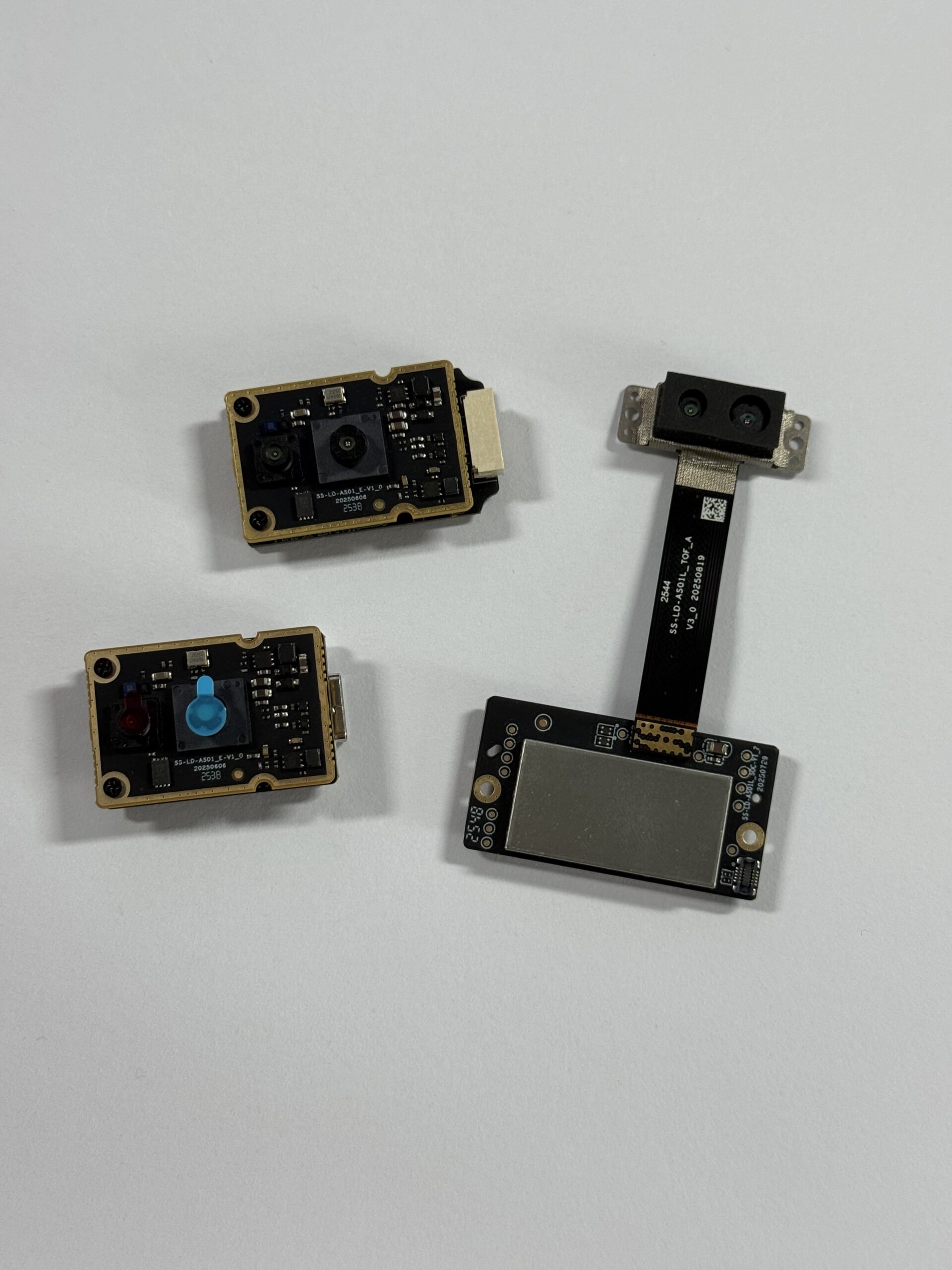
The DTOF Solid State LiDAR HM-LD1 is a compact solid-state dToF LiDAR module designed for real-time depth sensing, point cloud generation, and embedded 3D perception. It is suitable for robotics, UAVs, smart inspection devices, cameras, security systems, and development platforms that require portable LiDAR scanning capability without the size, weight, or cost of a larger survey-grade scanner. The module is based on SPAD dToF technology and is described as delivering real-time depth images and 3D point cloud data for accurate environmental perception.
In practical applications, HM-LD1 can support obstacle avoidance, distance detection, autonomous navigation, smart inspection, robotic vision development, UAV altitude hold, terrain following, autofocus, user presence detection, object recognition, volume measurement, and zone intrusion monitoring. Its compact size and low weight make it suitable for space-constrained robots and drones where payload and mounting space are limited. Its UVC, UDP, and UART interfaces help developers integrate the module with PCs, Raspberry Pi systems, flight controllers, embedded platforms, and Linux-based development environments.

| Specification | DTOF Solid State LiDAR HM-LD1 |
|---|---|
| Product Name | DTOF Solid State LiDAR HM-LD1 |
| Product URL | View HM-LD1 Product Page |
| Technology | Solid-state SPAD dToF LiDAR |
| Dimensions | 43.5 mm × 30 mm × 26.5 mm |
| Ranging Capability | Indoor: 0.5–25 m; Outdoor: 0.2–8 m |
| Ranging Accuracy | ±3 cm |
| Field of View | 60° horizontal × 45° vertical |
| Weight | 28 g |
| Resolution | 40 × 30 |
| Frame Rate | 10 fps |
| Interface | UART / UDP / UVC |
| Operating Temperature | -20 ℃ to 60 ℃ |
| Power Consumption | 1.2 W |
| Supported Development Platforms | SDKs for x86 Windows, x86 Linux, and ARM Linux |
| Typical Applications | Obstacle avoidance, distance detection, autonomous navigation, UAV altitude hold, terrain following, smart inspection, robotic vision, presence detection, object recognition, volume measurement, and zone intrusion monitoring |
View Product Details & Pricing ➔
HM-LD1 is positioned as a compact depth-sensing module rather than a bulky survey scanner. Its 28 g weight helps preserve drone flight time and reduces the structural burden on small robots. Its 1.2 W power consumption is useful for battery-powered platforms. Its 40 × 30 resolution and 10 fps frame rate are appropriate for lightweight embedded perception tasks such as obstacle presence, zone detection, and compact robotic vision rather than dense architectural scanning. For teams building a product, the availability of SDKs for x86 Windows, x86 Linux, and ARM Linux can reduce integration friction across development and deployment environments.
Download the product brochure: DTOF SSL HM-LD1 Product Brochure
Integration Workflow for Developers
Step 1 — Define the Sensing Task
⚙️ Start by defining the sensing task in measurable terms. Examples include detecting obstacles within 5 m, maintaining UAV altitude, triggering a zone intrusion alarm, estimating object volume, adding near-field 3D perception to an AMR, or capturing depth data for an AI perception pipeline. This step prevents the common mistake of selecting a scanner based on general claims instead of actual system requirements.
Step 2 — Choose Mounting Orientation
⚙️ Mounting orientation determines what the LiDAR scan can observe. A forward-facing robot installation may support obstacle avoidance. A downward-facing UAV installation may support altitude hold or terrain following. An angled installation may reduce blind spots. A smart camera installation may monitor a specific zone. Engineers should also consider protective window material, optical reflections, cable routing, enclosure clearance, heat, vibration, and whether the sensor view will be blocked by the vehicle body.
Step 3 — Select Interface Mode
⚙️ Select the interface that best matches the platform. UART may be appropriate for compact embedded control, simple distance workflows, or microcontroller-based systems. UDP may be suitable for networked data and higher-level processing. UVC can simplify camera-like stream integration. SDK support can shorten the path from first power-on to usable data visualization and application development.
Step 4 — Validate Data Output
⚙️ Validation should happen in the real environment, not only on a desk. Test range, dark surfaces, reflective surfaces, moving obstacles, sunlight, vibration, temperature, and latency. For outdoor applications, test different sun angles and target materials. For robots, test at expected travel speed and stopping distance. For UAVs, test vibration, mounting angle, ground texture, and flight controller integration. Logging and replay tools can help developers compare sensor behavior across scenarios.
Step 5 — Integrate With the Robotics Stack
⚙️ After validating basic output, integrate the data with the robotics or automation stack. This may include point cloud processing, depth image filtering, obstacle zone definition, sensor fusion, ROS or ROS 2 bridge development, AI perception, or control logic. LiDAR data is often strongest when combined with IMU, camera, wheel odometry, GNSS, radar, ultrasonic, or bumper sensors. The goal is not simply to create a scan; the goal is to create reliable perception that improves system behavior.
Step 6 — Prepare for Deployment
⚙️ Deployment preparation includes cable strain relief, enclosure design, power regulation, EMI review, firmware version control, environmental protection, technical support planning, and supply continuity. A prototype can tolerate loose wiring and manual resets. A deployed robot, drone, or inspection product cannot. Choosing a module with clear specifications and supplier support can reduce long-term maintenance risk.
Common Mistakes to Avoid
Mistake 1 — Buying Based on Range Alone
✅ Maximum range is only one part of LiDAR scan performance. Buyers must also evaluate accuracy, repeatability, field of view, frame rate, sunlight performance, object reflectivity, data output, interface compatibility, and integration support. A long-range claim is not enough if the data is unstable or not accessible in the required format.
Mistake 2 — Confusing 3D Model Quality With Sensor Quality
✅ A phone app may produce a visually pleasing mesh, but that does not mean it is the best sensor for machine perception. An industrial module may produce a lower-resolution depth map that is much more useful for real-time control because it offers defined interfaces, predictable output, and a practical mounting strategy. Visual quality and engineering usefulness are not the same metric.
Mistake 3 — Ignoring Interface Compatibility
✅ If the LiDAR sensor cannot communicate with the target controller, computer, or software stack, the project may require custom adapters, middleware, or extra development time. Interface support should be checked early. UART, UDP, and UVC each support different workflows, and SDK availability can be just as important as hardware specifications.
Mistake 4 — Underestimating Outdoor Conditions
✅ Outdoor operation can be difficult. Sunlight, dark surfaces, reflective materials, dust, rain, fog, vibration, and temperature changes can affect measurement stability. Buyers should test the actual environment rather than relying only on ideal specification values. Outdoor range is often shorter than indoor range, especially for compact sensors.
Mistake 5 — Overlooking Mechanical and Power Constraints
✅ A scanner may be technically capable but too heavy, too power-hungry, or too difficult to mount for a UAV or compact robot. Weight, dimensions, heat, cable routing, and power budget should be part of the first selection review. This is why compact modules such as HM-LD1 can be attractive for mobile platforms where every gram and watt matters.
LiDAR Scan FAQ
Is an iPhone LiDAR scan good enough for professional site surveys or robotics development?
What should I look for in an affordable portable LiDAR scanner that is better than a phone?
Can DIY or open-source LiDAR scanners work for real projects?
What is the difference between a LiDAR scan and a point cloud?
Is a higher-resolution LiDAR scanner always better?
Can LiDAR scanning work outdoors in sunlight?
What LiDAR scanner is best for a drone?
What LiDAR scanner is best for a robot?
How accurate is a portable LiDAR scan?
Do I need LiDAR, depth camera, radar, or ultrasonic sensing?
View Product Details & Pricing ➔
📚 References & Further Reading
- Industry Standard: IEEE Photonics Society
- Related Guide: DTOF Solid State LiDAR HM-LD1






