Latest LiDAR News: How Cost Drops & Solid-State Tech Are Democratizing Robotics Perception
If you’ve spent any time on a factory floor, managed a warehouse automation rollout, or tried to get a drone to hold altitude over uneven ground, you know the score. Historically, getting high-resolution, three-dimensional spatial awareness was an expensive, fragile headache. It was a luxury reserved for premium autonomous vehicle test fleets with massive budgets or heavily capitalized industrial setups. If you wanted 3D spatial scanning, you had to bolt a spinning, mechanical “coffee can” sensor to your rig, keep your fingers crossed that the bearings wouldn’t seize up, and write a massive check to legacy suppliers.
Here’s the deal: that era is officially over. The latest lidar news is dominated by a massive, structural shift. We are witnessing a rapid transition from fragile, expensive mechanical scanners to incredibly durable, affordable, silicon-based solid-state chipsets. Thanks to major breakthroughs in semiconductor manufacturing and optical design—specifically the maturation of direct Time-of-Flight (dToF) tech and Single-Photon Avalanche Diode (SPAD) arrays—complete 3D depth engines are now being etched directly onto silicon wafers.
In the shop, we don’t care about hype; we care about reliability, repeatability, and unit economics. This technical deep dive is going to skip the marketing fluff. We will explore how these massive cost drops are reshaping the robotics market, tear down the underlying physics of solid-state semiconductor components, and walk through the exact engineering parameters of the next generation of micro-LiDAR modules design.
Table of Contents
- 👉 1. Industry Paradigm Shift: Decoding the Latest LiDAR News
- 👉 2. Solid-State vs. Mechanical Architectures
- 👉 3. The Physics of Solid-State: Direct Time-of-Flight (dToF) & SPAD Arrays
- 👉 4. Hardware Spotlight: Deep-Dive Analysis of the DTOF SSL HM-LD1
- 👉 5. Multi-Scenario Industrial and Robotics Applications
- 👉 6. Developer Integration & Embedded Platform Compatibility
- 👉 7. Comprehensive Technical FAQ
1. Industry Paradigm Shift: Decoding the Latest LiDAR News
If you look at recent headlines in the spatial perception sector, you’ll notice a very clear, very interesting divergence. On one side, premium automotive manufacturers are loudly re-evaluating their dependency on ultra-high-cost, heavy, power-hungry mechanical LiDAR scanners or high-end MEMS equipment. Some automotive OEMs are even trying to ditch LiDAR entirely in favor of camera-only arrangements to hit aggressive consumer price points. But on the other side of the track—in the domestic, commercial, and industrial robotics markets—we are seeing an absolute gold rush of 3D sensor integration.
Why the split? It all comes down to the steep drop in manufacturing costs for solid-state architectures. By ditching the spinning mirrors, the high-precision alignment lasers, and the fragile optomechanical sub-assemblies of the past, chipmakers can now manufacture a complete 3D depth engine using classical semiconductor packaging techniques. This means we are no longer building sensors; we are printing them.
Look, this paradigm shift completely changes how engineering teams budget their bills of materials (BOM). For a long time, if you were designing an Autonomous Mobile Robot (AMR), an Automated Guided Vehicle (AGV), or a smart warehouse system, you were caught between a rock and a hard place. You either had to cripple your system’s spatial awareness by relying solely on cheap 2D ultrasonic sensors and basic cameras, or you had to swallow a massive billing pill to source legacy, industrial-grade 2D or 3D scanners from high-end suppliers like HOKUYO.
Today, the democratization of solid-state direct Time-of-Flight (dToF) micro-sensors provides multi-dimensional spatial points at a tiny fraction of the cost. For hardware leads and procurement managers, this means 3D perception is no longer a luxury earmark that risks getting cut during cost-reduction review cycles. Instead, it’s becoming a standard, highly accessible safety and navigation feature that can be integrated directly into compact robot chassis, light UAV frames, and smart factory lines to prevent collisions and guarantee precision docking.
2. Solid-State vs. Mechanical Architectures
To understand why solid-state LiDAR (SSL) is such a massive leap forward, we need to talk about what actually happens to traditional mechanical scanning hardware when you put it to work in a demanding industrial setting. Mechanical systems rely on physical, high-frequency motor rotation to sweep a laser beam across a field of view. It’s an elegant concept on paper, but on a rugged shop floor, those moving parts are ticking time bombs. Let’s look at the mechanical limitations that cause head scratching in the field:
- ⚙️ Continuous Mechanical Wear: High-speed bearings, electrical slip devices, and drive belts can’t run forever. In a 24/7 warehouse distribution center, continuous physical rotation eventually leads to runtime wear, alignment drift, and predictable mechanical failure.
- ⚙️ Vibration and Shock Vulnerability: When an industrial vehicle sweeps across expansion joints, runs over debris, or transitions over warehouse thresholds, it experiences sudden, sharp impacts. These physical shocks can easily knock spinning optical assemblies out of alignment, causing erratic spatial data, false positives, or sudden safety trips.
- ⚙️ Mass and Power Draw: Spinning motors, counterweights, and heavy protective housing add serious bulk and weight to your rig. If you’re designing a weight-sensitive platform like a micro-UAV or a compact robotic picking arm, that extra weight translates directly to shorter battery life and sluggish dynamics.
Solid-State LiDAR models completely rewrite this script by removing every single moving part from the optical path. Rather than sweeping a single laser beam back and forth with physical motors, the transmitter and receiver arrays are locked in permanent, static positions relative to one another. They use advanced micro-optics to flood and capture light across the entire field of view simultaneously. This simple, elegant construction yields immediate, practical benefits:
- ✅ Exceptional Lifespan and Reliability: With zero physical friction or mechanical strain, the internal components experience practically zero wear-and-tear. This yields an exceptionally high Mean Time Between Failures (MTBF), giving you peace of mind in high-vibration applications.
- ✅ Incredible Mass Savings: Ditching the drive motors and bulky balancing dynamic casings means the entire sensor module can be shrunk down to a highly compact payload—often weighing under 30 grams. You can mount these practically anywhere without throwing off your center of gravity.
- ✅ True Silicon Scaling: Because solid-state modules are fabricated using standard semiconductor lithography processes, the manufacturing cost curves behave like computer chips, not mechanical instruments. As production volumes scale, unit costs plunge, making mass fleet deployment highly economical.
3. The Physics of Solid-State: Direct Time-of-Flight (dToF) & SPAD Arrays
If you want to make an informed choice when sourcing spatial sensors, you need to understand the underlying physics. The magic of modern solid-state LiDAR comes down to two key technical pillars: direct Time-of-Flight (dToF) chronometry and Single-Photon Avalanche Diode (SPAD) receiver arrays.
In the spatial sensing world, there are two primary ways to calculate distance using a laser beam: Indirect Time-of-Flight (iToF) and Direct Time-of-Flight (dToF). While iToF measures the phase shift of a continuous modulated light wave, direct dToF is far more straightforward and rugged. It emits a brief, high-energy, nanosecond-level laser pulse and counts the exact duration it takes for those photons to exit the emitter, bounce off the target, and strike the receiver.
By using the constant speed of light ($d = \frac{c \cdot t}{2}$, where $c \approx 3 \times 10^8 \text{ m/s}$ and $t$ is the elapsed time), the system directly determines the physical distance. This direct measurement is highly resilient to multi-path reflections and ambient optical anomalies, making it exceptionally reliable. For a deep look at the underlying math and history of this methodology, you can read more about Time-of-Flight on Wikipedia.
Now, detecting those returning photons is a massive engineering challenge in itself. By the time a laser pulse travels to a target twenty meters away—especially a dark, non-reflective target—and bounces back, the returning signal is incredibly weak. Often, you are looking for just a handful of scattered photons.
This is where Single-Photon Avalanche Diode (SPAD) detectors save the day. Operating in Geiger-mode, these specialized semiconductor diodes are biased above their breakdown voltage. When even a single, lonely photon hits the active area, it triggers a massive avalanche current of millions of electrons. This extreme sensitivity allows the sensor to detect very weak reflections from distant or dark targets. When you arrange these SPAD detectors in a highly organized grid array, you get an active, solid-state receiver that can construct a complete 3D depth image across its field of view without needing physical scanning mirrors.
But what happens when you take this ultra-sensitive SPAD array outdoors under bright, punishing sunlight? Direct sunlight can hit the sensor with over 80,000 lux of ambient optical noise, which would easily saturate a basic receiver and bury the faint reflections of your laser.
Modern solid-state dToF designs beat this noise by combining physical and digital filters. First, they use narrow-band optical bandpass filters matched precisely to the laser’s wavelength (typically 940nm) to block out the vast majority of solar radiation. Second, the on-chip digital signal processors (DSPs) run advanced statistical histogram algorithms. By analyzing the arrival time of incoming photons over multiple quick pulses, the chip easily isolates the coherent peak of the laser return from the random, chaotic arrival of background solar photons. The result? Rock-solid ranging performance, even under the midday sun.
4. Hardware Spotlight: Deep-Dive Analysis of the DTOF SSL HM-LD1
If you want to see how these physics principles translate into a real-world, production-ready package, look no further than the DTOF Solid state LiDAR HM-LD1. This compact, industrial-grade module is a spectacular showcase of what modern solid-state dToF technology can do, packing a highly integrated SPAD core into a remarkably tiny form factor.
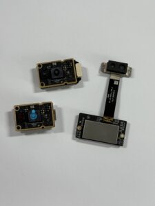
Figure 1: Dtof front
Optical Ranging Capabilities & Accuracy
The HM-LD1 is designed to handle tough, real-world operational environments, seamlessly adapting its performance based on surrounding light conditions:
- ⚙️ Indoor/Night Operational Range (0.5m to 25m): In indoor industrial zones or dark warehouses free of ambient infrared interference, the system easily tracks objects out to 25 meters, giving logistics AMRs plenty of runway to spot hazards and plan their paths.
- ⚙️ Outdoor Range (0.2m to 8m @ 80,000 Lux): Even when subjected to direct, harsh solar illumination of 80,000 Lux, the sensor maintains highly reliable ranging up to 8 meters. This direct outdoor capability makes it highly suited for measuring distances to hard-to-reach municipal infrastructures, such as bridges, overpasses, and dams.
- ⚙️ Precision Ranging Accuracy (±3cm): Because the core dToF chronometry clock has exceptional resolution, the module maintains an operating accuracy of ±3 centimeters across its active detection spectrum. This tight specification is essential for close-proximity docking, precision payload handling, and highly stable UAV flight control.
Comprehensive Technical Specifications
For engineering reviews, systems integration, and procurement evaluations, the complete physical and performance parameters of the DTOF Solid-State LiDAR HM-LD1 are detailed in the tables below:
View Product Details & Pricing ➔
5. Multi-Scenario Industrial and Robotics Applications
Because the HM-LD1 is designed around a lightweight physical footprint, extremely low electrical overhead, and a highly robust dToF calculation engine, it is incredibly versatile. It is deployed across a wide variety of industrial and robotic sectors:
Unmanned Aerial Vehicles (UAVs): Altitude Hold & Terrain Following
In the flight engineering world, excess weight is a complete dealbreaker. Every extra gram you bolt onto a drone frame directly translates to shorter flight times and decreased payload capacity.
Because the HM-LD1 core module weighs a mere 28 grams, it can be mounted to the underside of lightweight UAVs without affecting flight dynamics or power efficiency. Operating as a downward-facing sensor, it provides real-time, highly accurate distance-to-ground data. This enables ultra-stable altitude hold, precise terrain following, automated landing, and easy navigation over challenging obstacles like dense foliage, moving water, or complex physical structures.
Warehouse AMRs & AGVs: Active Obstacle Avoidance
Modern warehouse logistics routes are incredibly dynamic. Autonomous vehicles must navigate narrow aisles filled with moving workers, manual forklifts, and discarded inventory.
With its wide 60° x 45° field of view, a single front-mounted HM-LD1 can scan the entire vehicle path. It easily detects low-profile hazards, such as dropped pallets or forklift forks near the floor, which traditional 2D single-line scanners often miss entirely. Plus, because the sensor draws a modest 1.2W of power, it won’t drain your AMR’s batteries, keeping your fleet runtime high and boosting overall system efficiency.
Simultaneous Localization and Mapping (SLAM)
For robots exploring unknown and complex physical structures, generating reliable 3D point-cloud data packaging is critical for robust localization.
By pairing the HM-LD1’s depth stream with wheel odometry and IMU data, developers can easily generate rich 3D SLAM maps. This lets the robot identify, categorize, and navigate complex physical obstacles—like structural pillars, industrial racking, and safety guardrails—even in GPS-denied indoor environments.
Industrial Safety Cover & Zone Intrusion Monitoring
Smart factories must keep human workers safe around dangerous, high-speed automated equipment.
By projecting its 40 x 30 active depth grid over access pathways and robotic work cells, the HM-LD1 acts as an intelligent, high-density optical safety screen. Unlike traditional safety mats or simple light curtains that only check a single point of light, this sensor can monitor complex 3D volumes. It can trigger an immediate machine slowdown or emergency stop the moment an object or worker breaches a predefined safety zone, avoiding workplace accidents without interrupting normal production flows.
6. Developer Integration & Embedded Platform Compatibility
Look, we have all been there: you buy a piece of hardware with great specs on paper, get it to the testbench, and spend the next three weeks tearing your hair out because of compile errors, missing headers, or unsupported operating systems. The engineers behind the HM-LD1 deliberately designed the module to make integration as smooth as possible.
Multiple Hardware Interface Options
To ensure you can easily integrate this sensor with your existing hardware architectures, the HM-LD1 supports three distinct physical connection methods:
- ⚙️ UART (Universal Asynchronous Receiver-Transmitter): Ideal for low-level embedded system control, allowing you to feed raw distance values directly to microcontrollers, flight compute units, and ultra-low-power industrial processors without routing through an intermediate conversion chip.
- ⚙️ UDP (User Datagram Protocol): Designed for larger robotic platforms with onboard computers, enabling reliable, high-speed point-cloud data streaming over a local network.
- ⚙️ UVC (USB Video Class): This is a massive timesaver. UVC compatibility means you can plug the LiDAR module directly into a PC or single-board computer, and the OS will recognize it as a standard camera device. You can access the raw depth stream instantly, bypassing the need to compile custom USB drivers.
Complete SDK Support Across OS Environments
Instead of forcing your software team to write low-level register configuration code, the product includes comprehensive, proven SDKs for major operating systems:
- ✅ x86 Windows & Linux: Perfect for high-power industrial PCs, central server processing hubs, and desktop simulation testing.
- ✅ Arm Linux: Fully optimized for compact single-board computers, including the Raspberry Pi, NVIDIA Jetson series, and specialized embedded ARM architectures.
With native ROS/ROS2 compatibility nodes ready to go, your software team can spin up a node, subscribe to the topic, and start visualizing high-resolution 3D point-clouds in hours, rather than months.
Product Development Resources
To help you get started with mechanical and software prototyping, grab the official developer packages, CAD files, and technical schematics at the link below:
📥 Download the DTOF SSL HM-LD1 Product Brochure & Technical Datasheet
7. Comprehensive Technical FAQ
Why is there a clear polarization in recent LiDAR news, where some automakers drop it while low-cost systems integrate it?
This polarization comes down to contrasting speed requirements and target budgets. Automotive self-driving programs operating at highway speeds require long-range scans—often exceeding 200 meters—to allow safe braking times at 75 mph. Achieving this range requires high-power, multi-beam optical setups, complex cooling systems, and specialized scanning elements, which can drive system costs into thousands of dollars per car. To keeping vehicle pricing competitive for consumers, some passenger car makers are pivoting to purely camera-based neural networks.
Conversely, industrial AMRs, AGVs, warehouse safety systems, and terrain-following UAVs travel at lower, managed speeds (typically under 12 mph). Within these limits, they don’t need extremely long-range sensors; a highly robust, short-to-medium-range sensor (1m to 25m) provides ample reaction time. Transitioning from complex, fragile mechanical systems to monolithic solid-state dToF chips like the HM-LD1 allows robotics developers to bypass delicate mechanical failures and excessive costs. This shift enables affordable, robust 3D perception for industrial platforms without demanding premium budgets.
What is the future of LiDAR technology, and how does it address developer pain points?
The future of LiDAR lies in silicon-level component integration, moving away from complex, hand-assembled physical systems. This shift addresses major developer pain points across three primary areas:
- ✅ Hardware Reliability: Advancements in SPAD configurations and dToF DSP arrays deliver robust solid-state modules with no moving parts. This design eliminates physical wear-and-tear and easily handles operations in harsh, vibration-prone environments.
- ✅ Calibrated Data Out-of-the-Box: Legacy sensors often required developers to perform complex calibration steps to extract clean depth data. Modern solid-state chips include on-board processors that handle environmental filtering automatically, delivering ready-to-use 3D coordinates.
- ✅ Seamless Framework Support: Modern development platforms support standard communication interfaces like UVC or UDP. Combined with official ROS/ROS2 nodes and open-source SDKs, this allows engineering teams to implement and test 3D perception in hours, significantly accelerating development cycles.
How does the HM-LD1 handle multipath interference (ghost obstacles) in highly reflective industrial settings?
Industrial settings often feature challenging materials like polished epoxy floors, metal racking, and glass enclosures. These reflective surfaces can cause multipath interference, where the sensor’s optical signal reflects off multiple objects before returning, potentially generating “ghost” obstacles in the depth map.
The HM-LD1 mitigates this issue using its dToF architecture and statistical histogram filtering. While continuous-wave phase-shift systems can easily misinterpret overlapping signal phases, dToF measures the exact flight duration of individual photons. The onboard DSP builds a high-resolution photon histogram for each pixel zone. When a pulse bounces off multiple surfaces, it creates separate peaks in the histogram. The sensor’s firmware analyzes these curves, isolates and ignores the secondary reflections, and logs only the primary obstacle. This direct filtering ensures clean spatial data and minimizes false obstacle detections in reflective environments.
Why is the FOV of the HM-LD1 optimized at 60° (H) x 45° (V) rather than 360°?
While 360-degree coverage is useful for general mapping, a focused Field of View provides significant advantages for practical industrial integration:
- ✅ High Spatial Density: Spreading an active 40×30 resolution across a full 360-degree circle would yield extremely low angular detail. Focusing those 1,200 data points within a 60° × 45° window provides a much denser depth grid, allowing the system to reliably detect small obstacles like cables, thin pipes, and tool handles directly in the team’s path.
- ✅ No Moving Parts: True 360-degree coverage typically requires spinning mechanical mirrors or multiple expensive modules. A solid-state 60° × 45° configuration strikes the ideal balance for forward-facing obstacle avoidance, landing zone analysis, and path planning, providing excellent spatial awareness where the robot needs it most.
- ✅ Flexible Multi-Sensor Layouts: For applications requiring wider coverage, designers can easily network multiple low-cost, low-power (1.2W) HM-LD1 modules. This approach allows system architects to position sensors exactly where needed, tailoring the vehicle’s perception suite without the high cost and complexity of spinning mechanical LiDARs.
📚 References & Further Reading
- Industry Standard: HOKUYO Automation Scanning Technology and Industrial Safety Systems Solutions Group
- Related Guide: Explore fundamental timing configurations and mathematical layouts under the Wikipedia Direct and Indirect Time of Flight Physics Resource Page