


Dtof LiDAR Depth Sensor for Robotics: Compact 3D Sensing, Obstacle Avoidance & Fast Integration
Here’s the deal: a Dtof lidar depth sensor is not just another distance gadget. For robots, drones, smart cameras, and industrial automation equipment, it gives the system direct time-of-flight distance data in a compact solid-state package. In the shop, the real problem is rarely “Can we measure distance?” The harder question is whether the machine can get stable 3D perception in a tight mechanical envelope, use it outdoors when lighting is ugly, keep power draw under control, and feed the data into software without turning the project into a science experiment. Traditional rotating LiDAR units can be powerful, but they bring size, cost, moving parts, weight, and integration work that do not always make sense for compact robots, UAVs, embedded AI cameras, or space-limited industrial equipment.
The DTOF Solid state LiDAR HM-LD1 is a compact SPAD dToF solid-state LiDAR module built to output real-time depth images and 3D point cloud data for environmental perception. It offers a 60° horizontal by 45° vertical field of view, 40 × 30 resolution, 10 fps frame rate, ±3 cm ranging accuracy, UART / UDP / UVC interfaces, and SDK support for x86 Windows, x86 Linux, and ARM Linux. This guide walks through how dToF sensing works, what specifications actually matter, where HM-LD1 fits in robotics and UAV systems, and how engineering teams can approach integration for prototypes and deployed products.
Table of Contents
- 👉 What Is a Dtof LiDAR Depth Sensor?
- 👉 How dToF LiDAR Works
- 👉 dToF vs iToF vs Traditional LiDAR
- 👉 Robotics Depth Sensing Requirements
- 👉 HM-LD1 dToF Solid-State LiDAR Overview
- 👉 Real Product Specifications
- 👉 DTOF Solid state LiDAR HM-LD1 Product Showcase
- 👉 Point Cloud and Depth Map Output
- 👉 Obstacle Avoidance and Autonomous Navigation
- 👉 UAV and Drone Applications
- 👉 Industrial Inspection and Security Applications
- 👉 Integration Interfaces and SDK Support
- 👉 Selection Checklist for Engineers
- 👉 Why Choose MRP for dToF LiDAR Integration
- 👉 Technical FAQ
What Is a Dtof LiDAR Depth Sensor?
A Dtof lidar depth sensor is a direct time-of-flight sensing module that measures distance by sending out light and timing how long the reflected photons take to return to the receiver. “dToF” means direct Time of Flight, and LiDAR means light detection and ranging. Instead of trying to infer depth from visual texture, stereo camera matching, or object size, a dToF LiDAR module calculates distance from the travel time of light. That matters in robotics because machines need measured spatial information, not just pretty camera images.
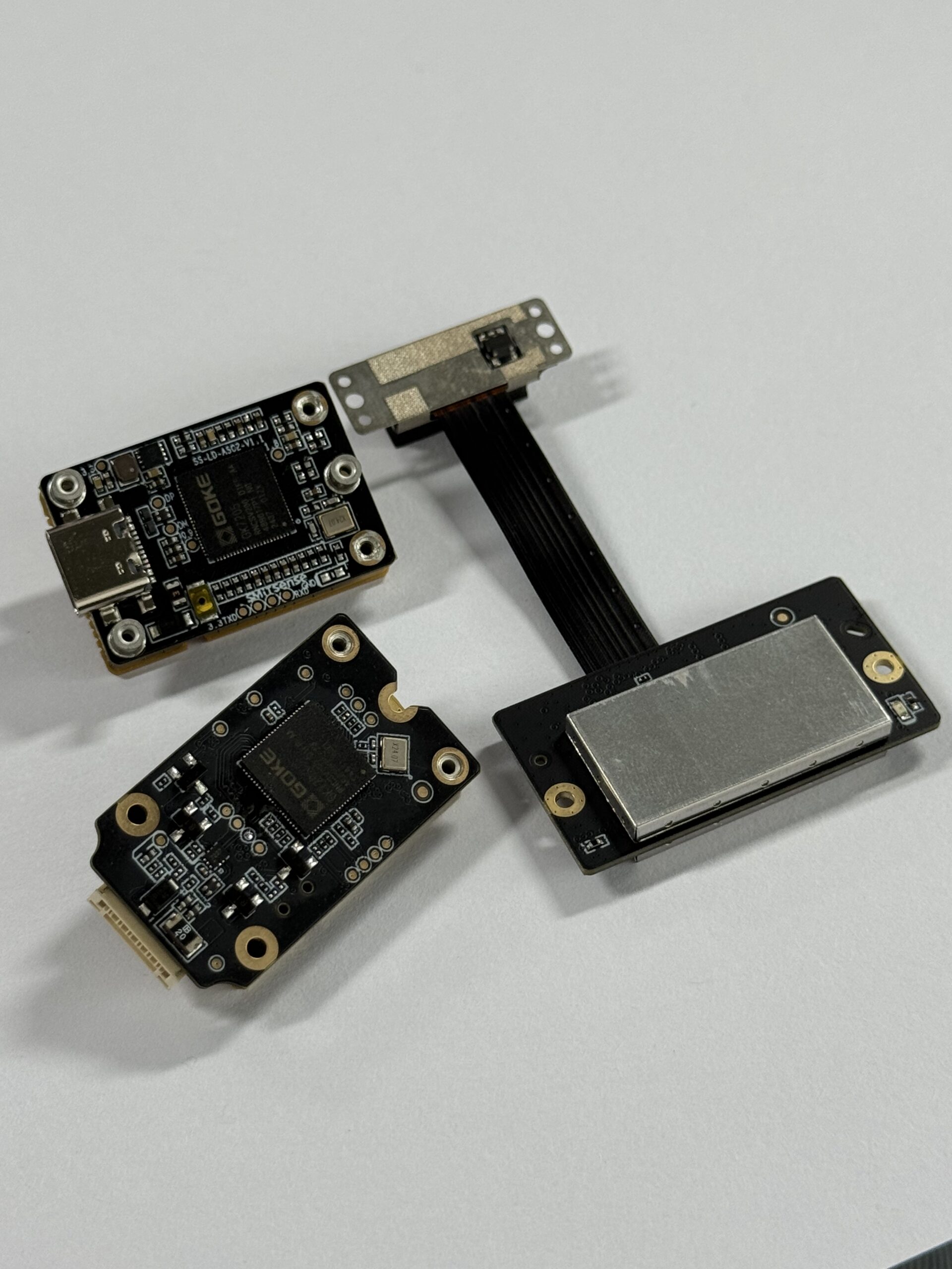
Look at it from the standpoint of a mobile robot on a factory floor. It needs to know how far away a pallet is, whether a person has stepped into its path, whether a docking target is close enough, or whether the floor surface ahead has changed. A solid-state depth sensor can help the system understand nearby shelves, walls, obstacles, terrain, infrastructure, and fixed zones. That depth information can feed collision avoidance, approach control, object presence detection, docking logic, inspection workflows, and machine perception. It can also work alongside cameras, IMUs, wheel odometry, GNSS, ultrasonic sensors, and other LiDAR devices.
The solid-state part is not marketing fluff. Many modern robotics platforms simply do not have room for a big rotating assembly. Small AMRs, compact drones, smart inspection tools, and embedded AI cameras often need low mass, low power draw, and a mounting footprint that does not force a full mechanical redesign. A compact dToF LiDAR module can provide structured 3D sensing for robotics without the bulk of a traditional scanning LiDAR. For broader autonomous platform applications, see this related guide on unmanned surface vehicle technology.
How dToF LiDAR Works
dToF LiDAR works by emitting a light pulse, receiving reflected light from a target surface, and calculating distance from the measured round-trip time. Since light travels at a known speed, the sensor estimates distance by multiplying the travel time by the speed of light and dividing by two. The division matters because the measured time covers the trip from the sensor to the object and back again. On paper, that sounds simple. In actual hardware, it takes precise timing, sensitive detection, optical design, thermal discipline, and signal processing to make that measurement useful in a small module.
In a robotics depth sensing system, the emitter projects light into the scene. Objects reflect some of that light back toward the receiver. The receiver detects returned photons, and internal processing converts timing data into distance values. Those values become a depth frame. A single-point rangefinder may tell you one distance. A depth sensor gives you many distance samples across a field of view, which lets software reason about objects, surfaces, and free space instead of reacting to one isolated measurement.
The HM-LD1 is based on SPAD dToF technology. SPAD stands for single-photon avalanche diode, a highly sensitive photon-detection technology used in compact time-of-flight sensing. SPAD-based detection is useful because returned light can be weak. Targets may be farther away, dark, angled, low reflectivity, or exposed to ambient illumination. A receiver that can detect very small amounts of returned light gives the module a practical advantage in real robotics work, especially when the system has to perform both indoors and outdoors.
For HM-LD1, the output resolution is 40 × 30. In plain terms, the module provides a structured depth image rather than one distance number. Each frame can be used as a compact depth map, and that depth map can also be converted into point cloud data. This gives software a way to interpret object positions in 3D space. Robotics teams combining LiDAR depth with GNSS or positioning modules may also evaluate navigation suppliers such as Unicore Communications for high-precision positioning components in broader autonomous systems.
dToF vs iToF vs Traditional LiDAR
Depth sensing technologies are not interchangeable. The right choice depends on range, field of view, resolution, frame rate, power budget, enclosure space, software architecture, and the environment where the machine will operate. dToF and iToF are both time-of-flight approaches, but they measure distance differently. dToF measures direct photon travel time, while iToF typically estimates distance from phase shift. Neither one wins every job. But dToF is often attractive when engineers want direct distance measurement, compact LiDAR hardware, and practical short-to-mid-range perception for robots, drones, and industrial equipment.
Compared with traditional rotating LiDAR, a solid-state dToF LiDAR depth sensor has no spinning tower. That can reduce mechanical complexity, simplify enclosure design, improve shock and vibration packaging, and make the sensor easier to mount on compact autonomous platforms. Rotating LiDAR systems still have a place in mapping, navigation, and wide-area autonomy. But they can be larger, heavier, more expensive, and more mechanically involved than a small solid-state module. If the job is front-facing obstacle awareness, docking support, presence detection, or fixed-zone monitoring, a compact dToF module may be the cleaner fit.
In the shop, this usually comes down to the job the sensor is expected to do. A drone may use dToF for altitude hold or terrain-relative movement. A mobile robot may use it for near-field obstacle detection. A smart camera may use it for user presence detection or autofocus. A security device may define a virtual detection zone. An embedded AI product may use distance data to make image recognition more reliable. These applications do not always need dense 360° mapping. They need reliable local spatial awareness in a compact, low-power package.
Larger LiDAR systems may still be the right answer for long-range outdoor autonomy, high-density mapping, wide-area scanning, or certified safety scanning. A compact dToF LiDAR depth sensor should be selected based on the actual sensing job, not on the assumption that one LiDAR type replaces every other LiDAR type. For many short-to-mid-range embedded perception tasks, dToF can reduce hardware complexity and speed up integration. For high-speed autonomy, large-scale surveying, or dense 3D reconstruction, it may be one useful input inside a larger perception system.
Robotics Depth Sensing Requirements
Before choosing a Dtof lidar depth sensor, engineers should define the sensing problem in measurable terms. Start with range. Indoor robots may need to detect shelving, walls, docking stations, pallets, people, machines, and low obstacles. Outdoor robots may need to detect terrain, barriers, infrastructure, equipment, or vegetation under sunlight and changing surface conditions. A sensor that behaves well at close range indoors may not behave the same way outdoors, where ambient light, target reflectivity, and target angle can weaken the optical return.
Accuracy is the next major parameter. HM-LD1 specifies ±3 cm ranging accuracy, which can be important for obstacle boundaries, docking assistance, approach distance control, inspection positioning, and safe navigation behavior. Accuracy should always be reviewed at the system level. Mounting vibration, calibration error, time synchronization, data filtering, lens contamination, and robot motion can all affect real-world performance even when the sensor itself has a strong specification.
Field of view determines how much of the environment the sensor sees in each frame. A 60° horizontal by 45° vertical FOV gives a useful rectangular sensing window for front-facing, downward-facing, or fixed-zone applications. Horizontal coverage helps detect obstacles entering the robot path. Vertical coverage helps identify floor objects, shelves, height changes, and terrain variation. FOV must be considered together with resolution because each depth sample represents a slice of the observed scene.
Frame rate affects responsiveness. HM-LD1 provides 10 fps, which can support real-time detection in many short-to-mid-range robotic and embedded applications. Whether 10 fps is enough depends on robot speed, stopping distance, control loop design, safety requirements, and how quickly the perception software processes each frame. Size, weight, and power also matter. With a 28 g weight and 1.2 W power consumption, HM-LD1 is practical for platforms where payload, thermal design, and battery capacity are constrained.
HM-LD1 dToF Solid-State LiDAR Overview
The DTOF Solid state LiDAR HM-LD1 is a compact SPAD dToF solid-state LiDAR module designed for real-time depth images and 3D point cloud output. It is positioned for robotics, UAVs, smart cameras, security systems, embedded vision development, obstacle avoidance, distance detection, autonomous navigation assistance, and industrial perception. Its solid-state design is a good fit when engineers need depth sensing without a bulky mechanical scanning assembly.
According to the supplied specification table, the HM-LD1 mechanical dimension is 43.5 mm × 30 mm × 26.5 mm, and the module weighs 28 g. The product copy also emphasizes compact housing for autonomous mobile robots with limited space for depth sensors and drones where weight affects flight distance. Because a separate product text statement contains a different dimensional description, the verified specification table should be treated as the primary source for engineering review.
The sensor supports indoor ranging from 0.5 m to 25 m and outdoor ranging from 0.2 m to 8 m. The product description also highlights useful measurement at 8 meters outdoors under clear summer daylight conditions assuming 80,000 lux. That makes the module relevant for projects needing short-to-mid-range perception in both controlled indoor environments and outdoor daylight scenarios. Still, a veteran engineer will always test against real target materials, surface angles, lighting transitions, dust, vibration, and mounting conditions before signing off on deployment.
Integration flexibility is one of the module’s strongest commercial advantages. HM-LD1 supports UART, UDP, and UVC interfaces. UART can work well for embedded controllers and flight controllers. UDP can support network-based streaming to computers or robotics processors. UVC can simplify camera-style host access for prototyping and visualization. MRP also offers SDKs for x86 Windows, x86 Linux, and ARM Linux, which supports development across PCs, Raspberry Pi-class platforms, embedded Linux systems, and industrial computing environments.
View Product Details & Pricing ➔
Real Product Specifications
Before selecting a Dtof lidar depth sensor for robotics, teams should evaluate mechanical envelope, range, accuracy, field of view, resolution, frame rate, interfaces, operating temperature, and power consumption. The HM-LD1 specifications below summarize the key engineering parameters for early feasibility review. These values are taken from the supplied product details and are presented as a practical engineering spec sheet for integration planning.
| Specification | DTOF Solid state LiDAR HM-LD1 |
|---|---|
| Dimension | 43.5 mm × 30 mm × 26.5 mm |
| Ranging Capability | Indoor: 0.5–25 m; Outdoor: 0.2–8 m |
| Ranging Accuracy | ±3 cm |
| Field of View | 60° horizontal × 45° vertical |
| Weight | 28 g |
| Resolution | 40 × 30 |
| Frame Rate | 10 fps |
| Interface | UART / UDP / UVC |
| Operating Temperature | -20 ℃ to 60 ℃ |
| Power Consumption | 1.2 W |
The product brochure is available here: DTOF SSL HM-LD1 Product Brochure. For engineering teams, this specification set is useful during early feasibility review, mechanical layout planning, interface selection, prototype architecture decisions, and supplier comparison. It gives the team enough hard numbers to decide whether the module deserves bench testing before deeper integration work begins.
DTOF Solid state LiDAR HM-LD1 Product Showcase

The DTOF Solid state LiDAR HM-LD1 is a compact SPAD dToF LiDAR depth sensor designed for robotics, UAVs, embedded vision, obstacle avoidance, distance detection, smart inspection, and 3D perception development. It delivers real-time depth images and 3D point cloud data, helping machines understand nearby objects, surfaces, and spatial zones with direct distance measurement.
Its compact 43.5 mm × 30 mm × 26.5 mm module size, 28 g weight, and 1.2 W power consumption make it practical for space-limited platforms. The module supports indoor ranging from 0.5 m to 25 m and outdoor ranging from 0.2 m to 8 m, with ±3 cm ranging accuracy and a 60° horizontal × 45° vertical field of view. The 40 × 30 resolution and 10 fps output provide structured depth data suitable for local perception, obstacle detection, zone monitoring, and development of robotic vision functions.
- ✅ Compact solid-state dToF LiDAR module for robots, UAVs, cameras, and security systems
- ✅ Real-time depth image and 3D point cloud output for environmental perception
- ⚙️ UART, UDP, and UVC interfaces for flexible integration workflows
- ⚙️ SDK support for x86 Windows, x86 Linux, and ARM Linux development
- ✅ Useful for obstacle avoidance, altitude hold, terrain following, distance detection, autofocus, presence detection, object recognition, volume measurement, and zone intrusion monitoring
View Product Details & Pricing ➔
Point Cloud and Depth Map Output
A depth map is a two-dimensional grid where each pixel or cell corresponds to a measured distance. For the HM-LD1, the 40 × 30 resolution creates a compact depth image that can be used to detect objects, surfaces, distance zones, and approximate shape changes in the environment. Unlike a standard camera image, where pixel values represent color or brightness, a depth map represents distance. That gives robots a more direct understanding of physical space.
Point cloud output adds another layer of usefulness. A point cloud maps distance samples into 3D space, allowing software to reason about object location, free space, approximate height, and spatial boundaries. A robot may use depth data to detect whether an object is crossing a safety boundary. A drone may use downward-facing depth information to estimate height over terrain. A security device may use a defined distance zone to detect intrusion. An inspection system may use depth changes to identify surface position or object presence.
In practical robotics systems, depth frames are usually processed through a software pipeline. The system acquires a depth frame, filters invalid or noisy points, transforms the data into the robot coordinate frame, segments obstacles or zones, and then sends usable information to a navigation, control, or AI perception layer. The exact algorithm depends on the platform and application. A slow indoor service robot, a small UAV, a smart camera, and an industrial monitoring system may all use the same raw sensor data in very different ways.
The key benefit is that a Dtof lidar depth sensor provides measurable spatial information without relying only on visual appearance. This is useful in environments where lighting, texture, and object color can make camera-only perception less reliable. Depth data can complement image recognition, improve object approach detection, support docking logic, assist obstacle avoidance, and create more robust embedded perception systems. Look, no single sensor makes a robot smart by itself, but clean distance data makes a perception stack a lot easier to trust.
Obstacle Avoidance and Autonomous Navigation
Obstacle avoidance is one of the most important use cases for a compact dToF LiDAR depth sensor. Mounted on the front of a robot, HM-LD1 can help detect walls, shelves, boxes, people, doorways, equipment, and other objects within its field of view. The 60° horizontal by 45° vertical FOV provides a practical sensing window for front-facing perception. The 40 × 30 depth output gives software a structured grid of distance values, allowing the system to identify occupied zones rather than relying on a single distance point.
For navigation assistance, the sensor can help distinguish nearby free space from blocked space. It can support behaviors such as slowing down near obstacles, confirming docking distance, detecting objects in a path, or triggering avoidance logic. It should be understood as part of a perception stack rather than a complete autonomous navigation solution by itself. A full navigation system may combine depth sensing with odometry, IMU data, cameras, maps, localization modules, or other LiDAR sensors depending on the platform requirements.
Depth data and point cloud information may also support SLAM systems, especially when combined with other localization inputs. The important word is “support.” A compact 40 × 30 depth sensor does not provide the same dense 360° mapping data as a high-resolution rotating LiDAR. However, it can contribute useful local 3D information for near-field mapping, obstacle boundaries, docking environments, and perception zones. Engineers should validate whether the sensor resolution, FOV, and frame rate match the robot’s motion speed and mapping needs.
Industrial robots often use multiple sensors for robustness. A dToF LiDAR depth sensor can contribute to situational awareness, but safety-rated applications may require certified safety sensors, redundant detection channels, and system-level validation. For inspection or aerial perception platforms, depth sensing may also be compared with stabilized vision payloads, such as those discussed in why the tri-spectral gimbal pod is game changer. The correct sensor architecture depends on mission type, safety requirements, operating environment, and software maturity.
UAV and Drone Applications
Drones and UAVs are highly sensitive to sensor weight, power consumption, mounting position, and integration complexity. The HM-LD1 weighs 28 g and consumes 1.2 W, making it attractive for compact aerial systems where payload capacity and battery life are limited. A Dtof lidar depth sensor can be mounted downward for altitude support, angled for terrain following, or forward-facing for obstacle awareness depending on the aircraft design and mission requirements.
Altitude hold is a common drone use case. Barometers and GNSS can provide useful altitude information, but near-ground precision may be limited in some conditions. A compact LiDAR depth sensor can help measure distance to the ground or to a surface below the aircraft. This can be useful for low-altitude inspection, landing assistance, indoor flight, terrain-relative movement, and operations where near-field distance matters more than absolute altitude. In the shop, this is where a small sensor can save a lot of tuning time.
Terrain following is another strong fit. During inspection, agriculture, mapping support, or low-altitude flight, measuring distance to surfaces can help the system maintain a more consistent standoff distance. The 60° × 45° field of view can provide a useful detection window when the sensor is mounted downward or at an angle. Engineers should validate performance against expected terrain materials, lighting conditions, vibration, aircraft speed, prop wash, mounting angle, and airframe constraints.
Drone teams combining depth sensing with GNSS positioning may also evaluate suppliers such as Beitian for navigation-related modules. In a practical UAV architecture, the dToF sensor may provide local distance data while GNSS, IMU, flight controller, visual payload, and mission software provide broader navigation and control functions. This multi-sensor approach helps match each sensing technology to the role it performs best.
Industrial Inspection and Security Applications
Beyond mobile robots and drones, a compact dToF LiDAR depth sensor can support industrial inspection and security applications. The supplied product description highlights distance measurement for objects that may be difficult for people to approach, including bridges, expressways, and dams. In these use cases, the value is not only the range measurement itself. The value is having compact distance data that can be mounted on robotic systems, inspection devices, or fixed monitoring equipment without building a large sensor assembly around it.
HM-LD1 supports outdoor ranging from 0.2 m to 8 m, and the product copy notes useful measurement at 8 m outdoors under clear summer daylight conditions assuming 80,000 lux. This makes it relevant for short-to-mid-range outdoor inspection tasks, while still requiring real-world validation under target materials, angles, weather exposure, dust, and lighting transitions. Bridges, roads, dams, and industrial structures can present varied reflectivity and surface geometry, so engineering teams should test representative conditions before deployment.
For security systems, depth maps can define virtual zones and detect when a person or object enters a restricted area. Unlike conventional motion detection, depth-based zone monitoring can use distance thresholds and spatial boundaries. This may support fixed-zone intrusion monitoring, smart access control, object presence detection, or industrial perimeter awareness. The sensor can also be applied in smart cameras for user presence detection, autofocus, object recognition support, and embedded AI vision functions.
Volume measurement is another possible application area. With calibration and suitable software, depth data can help estimate package size, bin fill level, object volume, or material presence. Final accuracy depends on sensor placement, resolution, target surface, calibration quality, and processing method. For many industrial systems, the practical advantage is that the same compact module can support distance detection, zone awareness, object presence, and 3D perception development within one hardware platform.
Integration Interfaces and SDK Support
Integration time is a major purchasing factor for robotics and embedded vision teams. A sensor may have attractive optical specifications, but if the interface is difficult to use or the software support does not match the target platform, development cost can climb fast. HM-LD1 supports UART, UDP, and UVC interfaces, giving engineers multiple ways to connect the sensor to controllers, PCs, embedded Linux devices, and development platforms.
UART is commonly used in embedded control systems. It can be appropriate when the sensor connects directly to a microcontroller, flight controller, or embedded board where serial communication is predictable and simple. UART may be useful when the application needs compact wiring, direct command communication, or integration with a control processor that does not require a full network stack. Engineers should confirm data format, bandwidth, voltage levels, connector design, and command protocol during system design.
UDP can be useful for networked data streaming. In robotics systems, it is common to process sensor data on an embedded Linux computer, industrial PC, or robot controller. UDP can support low-overhead transmission to a perception process, visualization tool, or data logging system. It may be suitable for prototypes where engineers want to monitor depth data in real time, or for deployed systems where the sensor data is streamed to a central processing unit.
UVC can simplify camera-style host integration. Many operating systems already support UVC devices, which can reduce friction during prototyping and visualization. For teams using PC-based development workflows, UVC may make it easier to access depth frames or display sensor output with familiar tools. This does not remove the need for calibration and data processing, but it can help teams move faster during early feasibility evaluation.
MRP offers SDKs for x86 Windows, x86 Linux, and ARM Linux. This matters because robotics teams often prototype on desktop computers and then deploy on ARM Linux systems such as Raspberry Pi-class platforms, Jetson-class embedded computers, or industrial control devices. A realistic integration workflow starts by confirming electrical and mechanical fit, selecting UART, UDP, or UVC, installing the SDK for the target platform, visualizing the depth map and point cloud, calibrating the coordinate frame, filtering noise and invalid points, feeding data into obstacle detection or navigation software, and validating both indoors and outdoors under expected lighting.
For ROS, OpenCV, and embedded AI workflows, engineers should avoid assuming that every example is already production-ready. Modules with SDKs and standard interfaces can reduce effort for ROS/OpenCV-style development, but teams should confirm available documentation, data format, driver support, and sample code before committing architecture. Need help selecting the right interface for your robot or UAV? Contact us about HM-LD1 integration.
Selection Checklist for Engineers
Choosing a Dtof lidar depth sensor should begin with mechanical constraints. Confirm available mounting space, sensor orientation, cable routing, vibration exposure, enclosure requirements, and total weight budget. For compact robots and drones, even small differences in size and weight can affect placement, center of gravity, airflow, protection, and maintenance access. HM-LD1’s 43.5 mm × 30 mm × 26.5 mm dimension and 28 g weight make it suitable for many compact designs, but engineers should still verify connector clearance, mounting stability, and field-of-view obstruction.
Optical and performance requirements should be reviewed next. Define required indoor range, required outdoor range, accuracy tolerance, field-of-view coverage, minimum detection distance, target reflectivity, ambient light conditions, and frame rate needs. HM-LD1 specifies indoor ranging of 0.5–25 m, outdoor ranging of 0.2–8 m, ±3 cm accuracy, 60° × 45° FOV, and 10 fps output. These specifications should be matched against robot speed, stopping distance, target size, surface materials, lighting transitions, and mission safety requirements.
Software compatibility is equally important. Confirm required output format, SDK compatibility, operating system, data visualization tools, point cloud processing needs, middleware integration, coordinate calibration, and logging requirements. If the product must integrate with ROS, OpenCV, a proprietary autonomy stack, or an embedded AI pipeline, confirm how the depth frames will be read, converted, filtered, and synchronized with other sensors. Also decide whether UART, UDP, or UVC is the best fit for the system architecture.
Deployment planning should include operating temperature, power budget, cleaning and maintenance, EMI/EMC review, enclosure design, field validation, and safety requirements. HM-LD1 specifies -20 ℃ to 60 ℃ operating temperature and 1.2 W power consumption, but the full system may experience additional heat, vibration, dust, moisture, cable strain, or electrical noise. After confirming technical requirements, teams can proceed to request pricing, samples, or purchasing support through checkout if purchasing is enabled for the selected configuration.
Why Choose MRP for dToF LiDAR Integration
MRP specializes in perception and positioning modules for robots and UAVs, with a focus on navigation devices and solutions. For engineering teams, that specialization matters because depth sensors are rarely purchased as isolated components. They must be mechanically installed, electrically connected, integrated into software, calibrated, tested, and validated under real operating conditions. A supplier familiar with robotics and UAV applications can help shorten the path from early evaluation to system deployment.
MRP has a professional independent R&D team focused on innovation in perception and positioning technology. This is relevant for customers building autonomous mobile robots, drones, industrial inspection systems, smart cameras, or embedded vision products that require more than a generic distance sensor. Technical context, interface selection, SDK guidance, and application-level integration support can reduce risk during prototype development and system qualification.
Technical support services are especially valuable when teams must choose between UART, UDP, and UVC, confirm SDK support, test depth maps, interpret point cloud data, or validate performance in indoor and outdoor environments. MRP also emphasizes direct manufacturing from the source factory, with in-house production for stable supply. For procurement engineers, supply stability, documentation access, and product continuity can be just as important as sensor specifications.
MRP also supports customized products on demand based on project requirements. Customization should always be confirmed through direct technical and sales communication, but the availability of project-oriented support can help teams working on specialized robotics, UAV, security, or industrial perception applications. For buyers evaluating HM-LD1, the most practical next step is to review the product details, download the brochure, and confirm integration requirements with the technical support team.
Technical FAQ
Are all ToF sensors LiDAR, and what makes a dToF LiDAR depth sensor different?
Can a compact dToF LiDAR replace bulky LiDAR towers in robots or smart devices?
How difficult is it to integrate a dToF LiDAR depth sensor into Raspberry Pi, Jetson, ROS, or embedded systems?
What range should I expect from the HM-LD1 dToF LiDAR depth sensor?
Is 40 × 30 resolution enough for robot obstacle avoidance?
Why does field of view matter in a dToF LiDAR depth sensor?
What interfaces are available on the HM-LD1, and which one should I choose?
Can the HM-LD1 be used outdoors?
What makes low weight and low power important for drones and mobile robots?
Does a dToF LiDAR depth sensor work for SLAM?
What operating conditions should be checked before deployment?
📚 References & Further Reading
- Industry Standard: Unicore Communications
- Industry Standard: Beitian
- Product Detail: DTOF Solid state LiDAR HM-LD1
- Product Brochure: DTOF SSL HM-LD1 Product Brochure
- Related Guide: The Surprising Power of USV
- Related Guide: Why the Tri-Spectral Gimbal Pod Is Game Changer






