

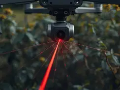
Best LiDAR Sensor for Drone Projects: Lightweight dToF Options for UAV Obstacle Avoidance, Mapping & Development
Here’s the deal: drone teams looking for the best lidar sensor for drone projects usually run into the same engineering trade-off. They need dependable depth perception, but they can’t just bolt a heavy, power-hungry, survey-grade payload onto a small UAV and call it a day. For obstacle avoidance, altitude assistance, terrain following, inspection, robotics education, and embedded perception development, the right LiDAR module is usually not the biggest scanner with the longest range. It’s the sensor that balances weight, power consumption, outdoor performance, field of view, frame rate, interface compatibility, SDK support, and integration simplicity.
This guide walks through how to choose a lightweight drone LiDAR sensor from an engineering point of view, with a special focus on compact solid-state dToF technology. We’ll compare drone LiDAR requirements for obstacle avoidance, mapping, inspection, and development, then take a close look at a real lightweight module: the DTOF Solid State LiDAR HM-LD1, a 28g SPAD dToF LiDAR with 60° × 45° FOV, 40 × 30 resolution, 10fps depth output, UART/UDP/UVC interfaces, and SDK support for Windows, Linux, and ARM Linux platforms. By the end, UAV developers, robotics teams, system integrators, and B2B buyers will know what specs matter, where compact dToF LiDAR fits, and when higher-end survey-grade systems are the right call.
Table of Contents
- 👉 Quick Answer: Best LiDAR Sensor for Drone Projects
- 👉 Why LiDAR Matters for UAV Obstacle Avoidance, Mapping, and Development
- 👉 How a Drone LiDAR Sensor Works: dToF, iToF, Scanning, and Solid-State Designs
- 👉 Key Selection Criteria for a LiDAR Sensor for Drone Integration
- 👉 Why Lightweight dToF LiDAR Is Useful for Small UAVs
- 👉 Recommended Lightweight dToF LiDAR: DTOF Solid State LiDAR HM-LD1
- 👉 Drone Use Cases: Obstacle Avoidance, Altitude Hold, Terrain Following, Inspection, and Mapping
- 👉 Integration Workflow: From Bench Test to UAV Flight Test
- 👉 Interfaces, SDKs, and Development Platforms
- 👉 Drone Mapping vs Obstacle Avoidance: Choosing the Right LiDAR Class
- 👉 When You Need RTK, GNSS, IMU, and Sensor Fusion
- 👉 Comparison Checklist for B2B Buyers and Engineering Teams
- 👉 FAQ: LiDAR Sensor for Drone Projects
- 👉 Conclusion: Choosing the Right Drone LiDAR Sensor
Quick Answer: Best LiDAR Sensor for Drone Projects
The best lidar sensor for drone projects depends on the mission. If you’re building a UAV for obstacle avoidance, you want a lightweight sensor with practical field of view, stable short-to-mid-range detection, low latency, and a software pipeline that can turn raw depth data into safe flight decisions. If the drone is doing altitude assistance or terrain following, you need consistent distance measurement, solid outdoor behavior, and a simple path into the flight controller or companion computer. A professional mapping drone, on the other hand, is a different animal entirely. That class usually needs high-end LiDAR scanning, RTK/GNSS, IMU data, time synchronization, calibration, and mapping software.
For small UAVs and development projects, the DTOF Solid State LiDAR HM-LD1 is a strong lightweight option because it weighs only 28g, consumes 1.2W, provides 40 × 30 depth resolution at 10fps, supports UART/UDP/UVC, and offers 0.5–25m indoor ranging plus 0.2–8m outdoor ranging. It is not meant to be a complete survey-grade mapping payload, but it is very relevant for UAV obstacle avoidance, perception prototyping, embedded development, inspection support, and lightweight robotic vision.
For projects that also require centimeter-level positioning, see our guide: What Is RTK? A Practical Guide. That becomes important when your drone has to relate sensor measurements to a global coordinate system instead of just reacting to nearby obstacles.
For small UAVs and development projects, the DTOF Solid State LiDAR HM-LD1 is a strong lightweight option because it weighs only 28g, consumes 1.2W, provides 40 × 30 depth resolution at 10fps, supports UART/UDP/UVC, and offers 0.5–25m indoor ranging plus 0.2–8m outdoor ranging. It is not positioned as a complete survey-grade mapping payload, but it is highly relevant for UAV obstacle avoidance, perception prototyping, embedded development, inspection support, and lightweight robotic vision.
HM-LD1 dToF Solid-State LiDAR: Compact Depth Sensing for UAVs & Robotics
Why LiDAR Matters for UAV Obstacle Avoidance, Mapping, and Development
LiDAR Gives Drones Direct Distance Awareness
LiDAR measures distance by emitting light and analyzing the return signal. For drones, that matters because a UAV doesn’t just need to “see” the environment; it needs to know how far away objects are. Cameras give you rich visual detail, but they don’t hand over metric range without extra computation. A LiDAR sensor can generate distance information that is much easier to turn into near, medium, and far detection zones for obstacle avoidance, low-altitude control, landing assistance, or inspection standoff monitoring.
Where Cameras Struggle and LiDAR Helps
Visual cameras can run into trouble when surfaces have low texture, lighting changes fast, or the scene is packed with repetitive patterns. Stereo cameras can perform very well in many robotics applications, but their depth calculation still depends on visual correspondence between images. LiDAR gives you another depth source, or a backup to the camera stack. For teams comparing LiDAR with depth cameras, review the 3D Stereo Vision Camera VIOBOT2. In many UAV systems, the best architecture is a mix of LiDAR, cameras, IMU, optical flow, GNSS, and onboard processing instead of betting everything on one sensor type.
Why Lightweight Perception Sensors Are Critical for UAVs
Every gram added to a drone changes the whole engineering picture. Extra payload can cut flight time, shift the center of gravity, increase vibration sensitivity, raise current draw, and complicate mounting. A heavy mapping payload may be fine on a large professional UAV, but it can be a headache on a small development drone, indoor UAV, inspection platform, or robotics education project. That’s why compact solid-state LiDAR modules are attractive: they provide useful depth information without turning the sensor package into the main mechanical and power constraint.
Drone LiDAR Is Not One Single Product Category
The phrase “drone LiDAR” covers multiple product classes. At one end are compact ToF modules used for obstacle awareness, altitude sensing, and prototyping. At the other end are professional multi-sensor mapping payloads with LiDAR scanners, inertial navigation, GNSS receivers, calibration workflows, and post-processing software. Between those extremes are industrial perception sensors, robotic navigation sensors, security depth modules, and inspection sensors. When selecting a lidar sensor for drone use, buyers should define the mission first, then pick the sensor class that actually fits it.
How a Drone LiDAR Sensor Works: dToF, iToF, Scanning, and Solid-State Designs
Direct Time-of-Flight, or dToF
Direct Time-of-Flight, commonly called dToF, measures the actual travel time of emitted light pulses. The sensor emits light, waits for the reflection, and calculates distance based on how long the light took to come back. That approach is useful for direct range measurement and can be built into compact modules. For drone developers, dToF gives a practical balance between size, range, power consumption, and real-time depth output.
Indirect Time-of-Flight, or iToF
Indirect Time-of-Flight, or iToF, estimates distance by measuring phase shift between emitted and received light signals. It shows up in some depth camera technologies and can be useful in robotics and human-machine interaction applications. That said, depending on the implementation, iToF systems may deal with range ambiguity, environmental sensitivity, or performance limits in certain lighting conditions. For UAV use, the point is not whether dToF or iToF is always better. The real question is whether the sensor’s actual specs match the mission.
Mechanical Scanning LiDAR
Mechanical scanning LiDAR uses moving parts to sweep laser beams across the environment. These sensors can deliver wide coverage and dense point cloud data, which is why they show up in a lot of robotics and mapping systems. But rotating or scanning systems may also be larger, heavier, more expensive, and more mechanically complex than compact solid-state modules. On small drones, that complexity can create mounting headaches, vibration concerns, and payload limits.
Solid-State LiDAR
Solid-state LiDAR avoids large rotating assemblies, which is why it’s attractive for UAVs and embedded systems. A compact solid-state LiDAR can be mounted forward for obstacle detection, downward for altitude assistance, side-facing for wall following, or angled downward for terrain awareness. Mechanical simplicity also helps development teams build more reliable prototypes because there’s less risk of a rotating mechanism interacting badly with airframe vibration, prop wash, or repeated takeoff and landing shocks.
SPAD-Based dToF LiDAR
The HM-LD1 is a solid-state LiDAR module based on SPAD dToF technology. SPAD-based dToF sensing enables real-time depth images and 3D point cloud data for accurate environmental perception. In UAV applications, that matters because perception algorithms can work with both 2D depth frames and 3D spatial information. The module can support obstacle avoidance, distance detection, autonomous navigation development, smart inspection, and robotic vision research.
Depth Map vs Point Cloud Output
A depth map is a 2D array where each pixel represents measured distance. A point cloud is a 3D spatial representation built from depth information and sensor calibration. For a drone, a depth map can be split into zones for decision-making, while a point cloud can support more advanced perception, visualization, and robotics algorithms. The HM-LD1 provides example ranging measurement data as point cloud and depth data, which makes it useful for both basic distance decisions and development of more advanced perception pipelines.
Key Selection Criteria for a LiDAR Sensor for Drone Integration
Weight and Payload Budget
Weight is one of the first specs to check. A drone LiDAR sensor has to be light enough that it doesn’t chew up flight time or throw off the center of gravity. For small drones, a 28g module is a lot easier to integrate than a large mapping payload. And the sensor is never the only payload item. Engineers also need to account for mounting brackets, cables, vibration isolation, voltage regulators, companion computers, and protective housing if the UAV operates outdoors.
Power Consumption and Flight Time
Power consumption hits flight time directly and it also affects thermal design. A 1.2W module is reasonable for embedded platforms where more than one sensor may share a power rail. Even so, engineers should still check peak current, voltage stability, and regulator headroom. A drone often carries cameras, telemetry radios, GNSS receivers, flight controllers, companion computers, and other sensors, so even a low-power LiDAR needs to be included in the full power budget.
Outdoor Ranging Capability
Indoor and outdoor ranging need to be evaluated separately. Sunlight can boost optical background noise and reduce effective range for many depth sensors. The HM-LD1 supports 0.5–25m indoors and 0.2–8m outdoors. The product details note accurate measurement even at 8 meters on a clear summer day under high illumination conditions, assuming around 80,000 lux. For drone projects, that outdoor range is relevant for near-field safety, inspection support, and terrain awareness, but it still has to be validated under the real mission conditions.
Ranging Accuracy
The HM-LD1 specifies ±3cm ranging accuracy. That’s useful for obstacle detection, distance awareness, altitude support, and development testing. It’s important not to confuse that with complete mapping accuracy. A LiDAR module can measure distance relative to the sensor, but survey-grade deliverables require positioning, orientation, synchronization, calibration, and mapping software. For a perception system, ±3cm can be very useful. For legal land survey deliverables, the accuracy question is completely different.
Field of View
Field of view determines how much of the scene gets covered. The HM-LD1 provides a 60° horizontal × 45° vertical FOV. For forward obstacle detection, that can cover a practical area in front of a UAV. Developers can split the depth image into left, center, right, upper, and lower regions to detect obstacles and generate warnings or avoidance commands. If you need full 360° coverage, you’ll need multiple sensors or a different LiDAR architecture.
Resolution and Frame Rate
The HM-LD1 outputs 40 × 30 resolution at 10fps. Think of that as a lightweight depth grid, not dense high-resolution mapping data. For embedded decision-making, lower resolution can actually help because it reduces processing load and bandwidth. For obstacle avoidance, the algorithm often needs to know whether a zone is occupied and how far away the obstacle is, not whether it can reconstruct a photorealistic model of the environment.
Interface Compatibility
Interfaces shape the whole system architecture. UART is useful for microcontrollers, flight controllers, and simple embedded control. UDP is useful for networked processing on a companion computer. UVC is useful for camera-like integration with PCs and Linux platforms. The HM-LD1 supports UART/UDP/UVC, which gives developers flexibility as they move from bench testing to onboard processing and flight integration.
SDK and Development Support
SDK support can decide whether a sensor becomes a useful product or just a frustrating part on a shelf. MRP offers SDKs for x86 Windows, x86 Linux, and ARM Linux, which lets teams develop across different operating systems and architectures. That matters for UAV developers who may start with a Windows laptop, move to a Linux workstation, and then deploy to a Raspberry Pi, Jetson-class companion computer, or ARM Linux board.
Operating Temperature
Operating temperature matters in industrial UAV deployments. The HM-LD1 operates from -20℃ to 60℃. That range is fine for many indoor and outdoor robotics environments, but engineers still need to think about enclosure design, airflow, solar heating, battery temperature, and local regulations. A drone sitting in direct sun or flying near hot industrial surfaces can see thermal conditions that are very different from ambient air temperature.
Mechanical Mounting and Vibration Considerations
Drone sensors have to survive vibration, airframe resonance, landing impacts, and cable movement. Mounting should keep the optical window clear of propellers, landing gear, wires, and payload frames. The module should be aligned with the intended detection zone and protected from dust or water if the mission requires it. If your UAV prototype needs to move UART-based sensor data wirelessly during bench testing, see: Stop Dragging a Cable: Make Any UART/Pose/Odometry Sensor Wireless with an ESP8266 Bridge.
Why Lightweight dToF LiDAR Is Useful for Small UAVs
Compact Form Factor for Small Airframes
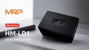
Small drones don’t have the payload capacity or mechanical real estate of large professional UAVs. A compact module such as the HM-LD1, with a listed dimension of 43.5mm × 30mm × 26.5mm and a weight of 28g, is easier to fit into tight spaces. The product description also emphasizes compact and lightweight integration for autonomous mobile robots and drones where weight affects flight distance. In the shop, that translates to less bracket hardware, fewer mounting headaches, and less need for major airframe redesign.
Low Power for Battery-Powered Robotics
Battery-powered platforms live and die by energy management. A 1.2W LiDAR module is easier to work into a UAV power budget than a high-power mapping payload. That leaves more room for the flight controller, propulsion, communication system, companion computer, and other perception sensors. Lower power also helps hold down thermal load, which matters when the sensor is tucked inside a compact enclosure or mounted near other electronics.
Direct Depth Data for Real-Time Perception
dToF LiDAR provides direct depth data that can be used for real-time perception. For drones, the engineering trick is turning depth frames into flight-relevant information. A developer might compute the minimum distance in the center zone, detect whether the lower portion of the image indicates rising terrain, or monitor a side-facing zone for wall-following. The HM-LD1’s depth map and point cloud output support exactly those kinds of development workflows.
Solid-State Design for Easier Mechanical Integration
A solid-state design can make mechanical integration easier because it avoids a large rotating assembly. That’s valuable for drones that see vibration, rapid attitude changes, and repeated takeoff or landing impacts. It also lets the sensor sit in a fixed position where the detection direction is predictable. Forward-facing mounting may support collision avoidance, while downward-facing mounting may support altitude assistance and landing support.
Useful Outdoor Detection Range for Near-Field UAV Safety
The HM-LD1’s outdoor ranging capability of 0.2–8m is relevant for near-field UAV safety and inspection workflows. It can help detect objects that are close enough to matter for slow or moderate-speed operation. But outdoor LiDAR performance depends on target reflectivity, sunlight, angle, weather, and algorithm thresholds. Engineers should not design around maximum range alone. They should test realistic targets and set conservative safety margins.
Recommended Lightweight dToF LiDAR: DTOF Solid State LiDAR HM-LD1
The DTOF Solid State LiDAR HM-LD1 is a compact SPAD dToF LiDAR module built for real-time depth sensing and 3D point cloud output. For drone teams, its main advantages are its 28g weight, 1.2W power consumption, compact housing, multiple data interfaces, and compatibility with common development platforms. It is suitable for UAV obstacle avoidance, altitude assistance, autonomous navigation development, robotic vision research, smart inspection, SLAM research, zone intrusion monitoring, and embedded perception prototypes.
HM-LD1 supports indoor or nighttime ranging up to 25m and outdoor daytime ranging up to 8m. The product description highlights accurate measurement even from long outdoor distances such as 8 meters on a clear summer day under high illumination conditions. That makes it useful for measuring distances to structures or objects that people may not be able to approach easily, including bridges, expressways, dams, warehouses, industrial facilities, and infrastructure inspection targets.
View DTOF Solid State LiDAR HM-LD1
Download DTOF SSL HM-LD1 Product Brochure
View Product Details & Pricing ➔
| Specification | DTOF Solid State LiDAR HM-LD1 |
|---|---|
| LiDAR Type | Solid-state dToF LiDAR based on SPAD technology |
| Dimension | 43.5mm × 30mm × 26.5mm |
| Weight | 28g |
| Indoor Ranging Capability | 0.5–25m |
| Outdoor Ranging Capability | 0.2–8m |
| Ranging Accuracy | ±3cm |
| Field of View | 60° horizontal × 45° vertical |
| Resolution | 40 × 30 |
| Frame Rate | 10fps |
| Interfaces | UART / UDP / UVC |
| Operating Temperature | -20℃ to 60℃ |
| Power Consumption | 1.2W |
| Supported SDK Platforms | x86 Windows, x86 Linux, ARM Linux |
| Typical Applications | UAV obstacle avoidance, altitude assistance, terrain following, distance detection, autonomous navigation, robotic vision development, smart inspection, SLAM research, zone intrusion monitoring |
Why HM-LD1 Fits Lightweight Drone Development
HM-LD1 fits lightweight drone development because it gives engineers usable depth output without the weight and power burden of a large LiDAR scanner. Its 28g weight and compact package make it practical for small UAVs where payload capacity is tight. Its 1.2W power consumption is suitable for battery-powered robotics. Its UART, UDP, and UVC interfaces lower integration friction and let the same module move across laboratory evaluation, embedded Linux development, and flight controller integration.
Where HM-LD1 Performs Best
HM-LD1 performs best in applications where compact 3D sensing, distance awareness, and near-field perception matter more than survey-grade mapping density. Good fits include forward obstacle detection, downward altitude assistance, terrain following at controlled speeds, smart inspection, indoor UAV navigation development, robotic vision development, and SLAM research. It can also support user presence detection, object recognition workflows, volume measurement concepts, and zone intrusion monitoring in security or automation systems.
Where a Higher-End Mapping LiDAR May Be Required
A higher-end mapping LiDAR may be required when the final deliverable is a georeferenced, survey-grade point cloud. In that case, the LiDAR sensor alone is not enough. The system must include RTK or PPK GNSS, an IMU, timestamp synchronization, calibration between sensors, trajectory estimation, and mapping software. HM-LD1 is best viewed as a compact perception and development module, not as a complete professional aerial surveying payload.
Recommended Development Platforms
Because HM-LD1 supports SDKs for x86 Windows, x86 Linux, and ARM Linux, it’s a good fit for development on PCs, Linux workstations, Raspberry Pi-class computers, Jetson-class platforms, and embedded Linux boards. A practical workflow is to start with a PC for visualization, move to a companion computer for onboard processing, then send processed warnings or control signals to the UAV flight controller. That staged approach cuts risk and helps engineers validate each piece before autonomous flight tests.
Drone Use Cases: Obstacle Avoidance, Altitude Hold, Terrain Following, Inspection, and Mapping
Forward Obstacle Avoidance
A forward-facing LiDAR can detect obstacles in the drone’s flight path. With a 60° × 45° FOV, HM-LD1 can be used to build detection zones such as left, center, and right regions. A simple algorithm might slow the UAV when the center zone falls below a safe threshold, while a more advanced algorithm could combine LiDAR data with camera classification and IMU data. For safe design, engineers should avoid tying raw distance data directly to aggressive maneuvers without filtering, confidence checks, and fail-safe logic.
Downward Altitude Assistance
A downward-facing LiDAR can provide distance-to-ground awareness. That can support landing assistance, low-altitude flight, terrain-relative hovering, and height estimation in indoor or GNSS-denied environments. Downward sensing is especially useful when barometric altitude isn’t good enough for close-to-ground operations. Still, ground surface reflectivity, slope, dust, water, grass, and sunlight can all affect readings, so real-world testing is essential.
Terrain Following
Terrain following means the drone has to hold a safe distance from changing surfaces. A downward or angled-forward LiDAR can help identify rising terrain, slopes, platforms, or infrastructure elements. Compact dToF LiDAR is useful in slow-speed terrain awareness scenarios, especially when paired with conservative control logic. High-speed terrain following requires careful evaluation of range, frame rate, flight dynamics, and stopping distance.
Industrial Inspection
Industrial inspection drones often need to maintain a safe standoff distance from bridges, expressways, dams, walls, tanks, machinery, and facility structures. HM-LD1 can help by giving distance data to objects that may be difficult or unsafe for people to approach. Its compact size makes it easier to mount on inspection UAVs where cameras, lighting, and communication systems may already take up most of the payload budget.
Indoor UAV Navigation Development
Indoor drones work in GPS-denied environments and often depend on onboard perception. LiDAR can help detect walls, doors, shelves, machines, and structural features. HM-LD1’s 0.5–25m indoor ranging capability is suitable for many indoor robotics labs, warehouses, education platforms, and research environments. Developers may combine LiDAR with visual odometry, optical flow, IMU data, and SLAM algorithms to estimate motion and avoid obstacles.
SLAM and Robotic Vision Research
SLAM research benefits from sensors that produce repeatable depth data and point cloud output. HM-LD1’s 40 × 30 depth frame and point cloud capability make it useful for lightweight perception development. It’s not a dense survey scanner, but it can support algorithm testing, occupancy detection, zone monitoring, and compact 3D perception experiments. Researchers can evaluate how lower-resolution depth data behaves in embedded systems with limited compute resources.
Entry-Level Mapping and Terrain Awareness
Compact LiDAR can support entry-level mapping concepts and terrain awareness, but buyers need to understand the difference between perception mapping and professional surveying. A drone can use compact LiDAR to build local awareness, detect obstacles, and visualize nearby structures. Survey-grade mapping requires a complete georeferenced system with positioning and motion compensation. That distinction matters for procurement teams because it prevents overpromising what a compact sensor can really deliver.
Integration Workflow: From Bench Test to UAV Flight Test
Step 1: Define the Drone Mission
Start by defining the mission. Is the drone avoiding obstacles, holding altitude, following terrain, inspecting infrastructure, or supporting research? The answer drives mounting location, required range, field of view, processing architecture, safety thresholds, and test procedures. A forward obstacle avoidance system is not the same as a downward landing support system.
Step 2: Select Mounting Position
Mount the LiDAR based on the detection goal. Forward-facing mounting supports collision avoidance. Downward-facing mounting supports altitude and landing assistance. Side-facing mounting supports wall following or inspection. Angled forward/downward mounting can support terrain awareness. The mounting position should avoid propeller interference, landing gear obstruction, vibration hotspots, and reflective parts of the airframe.
Step 3: Validate Power and Thermal Requirements
Confirm the 1.2W load within the complete UAV power system. Engineers should check voltage regulation, cable length, connector reliability, current margin, thermal environment, and electromagnetic compatibility. Power quality matters a lot when sensors share rails with motors, radios, or companion computers.
Step 4: Connect the Interface
Choose the interface based on the development stage. UVC may be convenient for fast visualization. UDP may be better for networked processing on a Linux companion computer. UART may be the right move for embedded control or flight controller communication. The availability of all three interfaces gives the HM-LD1 flexibility from early evaluation through system deployment.
Step 5: Visualize Depth Map and Point Cloud Data
Before you hook it into flight logic, visualize the depth map and point cloud data. Make sure the sensor sees expected objects, that the field of view is aligned properly, and that distance measurements are reasonable. Visualization helps you catch mounting mistakes, reflections, blocked regions, unexpected noise, and outdoor performance limits before the UAV ever goes autonomous.
Step 6: Build Detection Zones
Convert depth data into detection zones. For example, a forward-facing system may analyze left, center, and right regions. A downward-facing system may calculate median ground distance. Apply filtering to reduce noise and ignore invalid readings. Detection zones make depth data easier to translate into control decisions.
Step 7: Integrate with Flight Logic
Don’t connect raw LiDAR output to aggressive flight maneuvers right away. Use conservative thresholds, speed limits, and fail-safe behaviors. Flight logic should consider sensor confidence, vehicle velocity, braking distance, mission mode, and operator override. The goal is to improve safety, not create unstable reactions to noisy data.
Step 8: Conduct Static Ground Testing
Test the sensor on the ground with real target materials. Evaluate walls, poles, floors, grass, concrete, metal, glass, and dark objects if they matter to the mission. Test at different distances and lighting conditions. Record data so algorithm thresholds can be tuned before flight.
Step 9: Perform Tethered or Low-Speed Flight Testing
After bench and ground validation, move into controlled flight tests. Start with tethered tests, protective cages, or low-speed indoor flights where possible. Confirm that vibration, motion, attitude changes, and airflow do not create unacceptable measurement problems. Add complexity gradually.
Step 10: Tune Thresholds for Outdoor Conditions
Outdoor testing should include different sunlight conditions, target reflectivity, flight angles, and environmental backgrounds. Because optical sensors can behave differently outdoors than indoors, engineers should tune thresholds for real mission conditions. Conservative margins are especially important when a compact LiDAR is used for safety-related functions.
Interfaces, SDKs, and Development Platforms
UART for Embedded and Flight Controller Integration
UART is a simple serial interface that’s common in embedded systems. For drone LiDAR integration, UART may be useful when a microcontroller or flight controller receives processed distance data or simple measurement packets. It also helps with prototypes where low wiring complexity is important.
UDP for Networked Computing
UDP is useful when a companion computer processes sensor data over a networked architecture. In robotics, UDP can support data streaming to Linux applications, visualization tools, or custom perception pipelines. It works well when depth data or point cloud information needs to move between devices with low overhead.
UVC for PC and Linux Visualization
UVC allows camera-like integration. That can be handy for early testing because developers can use familiar video-device workflows on PCs and Linux platforms. For a drone team, UVC can speed up the process of seeing data, debugging field of view, validating measurement behavior, and building prototype applications.
SDK Support for x86 Windows
Windows SDK support is useful for lab evaluation, demonstrations, and engineering teams that prefer PC-based testing. A Windows environment can help procurement teams and application engineers quickly verify sensor output before they commit to embedded integration.
SDK Support for x86 Linux
Linux SDK support matters for robotics middleware, perception development, automation software, and research environments. Many UAV developers use Linux workstations to prototype algorithms before moving them onto onboard computers. Linux support also improves compatibility with robotics tools and custom data pipelines.
SDK Support for ARM Linux
ARM Linux support is especially important for drone companion computers, Raspberry Pi-class systems, and Jetson-class embedded platforms. Those boards are common in UAV development because they offer onboard compute while still staying relatively compact and power efficient. HM-LD1’s ARM Linux SDK support helps developers move from desktop testing to onboard deployment.
Typical Development Stack: Raspberry Pi, Jetson, PC, and Flight Controller
A typical development stack may start with a PC for visualization and data logging. The next stage may use Raspberry Pi or Jetson-class hardware for onboard processing. The processed output can then be sent to a flight controller as obstacle warnings, distance estimates, or behavior triggers. That staged workflow is safer and easier to maintain than trying to build a complete autonomous flight system all at once.
Drone Mapping vs Obstacle Avoidance: Choosing the Right LiDAR Class
Obstacle Avoidance LiDAR
Obstacle avoidance LiDAR is optimized for real-time perception, practical detection range, low weight, and integration with flight logic. It helps the drone determine whether an object is nearby and whether action is required. HM-LD1 fits this category for lightweight UAV development because it provides depth map and point cloud data in a compact, low-power form factor.
Development and Research LiDAR
Development LiDAR should be easy to connect, visualize, and program. SDK availability, interface flexibility, and platform support matter more than raw range alone. The HM-LD1 supports UART, UDP, and UVC, along with SDKs for x86 Windows, x86 Linux, and ARM Linux. That makes it suitable for universities, R&D labs, industrial prototypes, and robotics teams.
Inspection and Distance Measurement LiDAR
Inspection applications often need stable distance measurement to structures rather than dense large-area mapping. A compact dToF LiDAR can help monitor standoff distance, support approach control, or detect nearby infrastructure. For bridges, expressways, dams, and industrial facilities, that can improve safety and repeatability when paired with careful flight procedures.
Survey-Grade Mapping LiDAR
Survey-grade mapping LiDAR is a different class. It requires a professional scanning system, a high-quality IMU, GNSS/RTK or PPK, time synchronization, sensor calibration, trajectory processing, and mapping software. For GNSS module and positioning technology context, see u-blox. A compact module may support local awareness, but survey-grade mapping needs a complete system.
Why Maximum Range Alone Is Not Enough
Maximum range is only one spec. A drone LiDAR sensor should be judged on range, accuracy, field of view, resolution, frame rate, outdoor performance, interface, SDK, mounting constraints, power draw, and environmental reliability. A long-range sensor that’s too heavy or too hard to integrate may be less useful than a compact sensor that actually fits the mission. B2B buyers should define application requirements before they compare models.
When You Need RTK, GNSS, IMU, and Sensor Fusion
Why LiDAR Alone Is Not Enough for Georeferenced Mapping
A LiDAR sensor measures distance relative to the sensor. It does not automatically know where the drone is on Earth, how it is oriented, or how each measurement should land in a global coordinate frame. For georeferenced mapping, the system needs position, attitude, timing, calibration, and processing. That’s why professional mapping payloads are systems, not just sensors.
RTK for Centimeter-Level Positioning
RTK GNSS provides centimeter-level positioning under suitable conditions. If a UAV project needs accurate georeferenced outputs, RTK or a related positioning method may be required. For a practical introduction to RTK positioning, read: What Is RTK? A Practical Guide.
IMU for Motion Compensation
An IMU measures angular velocity and acceleration, which helps estimate drone attitude and motion. During flight, the LiDAR is always moving, rotating, and vibrating. Without motion compensation, point cloud data can get distorted. Survey-grade systems require careful synchronization and calibration between LiDAR and IMU coordinate frames.
GNSS/INS and Time Synchronization
Professional UAV mapping systems often use GNSS/INS integration. Time synchronization makes sure LiDAR points, GNSS positions, and IMU measurements line up with the same moments in flight. Even small timing errors can create mapping errors when the drone is moving. For professional positioning and navigation technology references, see Bynav Technology.
Sensor Fusion for Professional UAV Systems
Sensor fusion combines LiDAR, GNSS, IMU, cameras, barometers, and other data sources to estimate position, motion, and environment structure. For obstacle avoidance, sensor fusion can improve robustness. For mapping, it’s essential. Compact dToF LiDAR can be one useful perception element, but system-level performance depends on the whole architecture.
Comparison Checklist for B2B Buyers and Engineering Teams
Technical Checklist
Before selecting a lidar sensor for drone integration, ask the following: What is the indoor range? What is the outdoor range? What is the ranging accuracy? What field of view is provided? What is the resolution? What is the frame rate? Does it output a depth map, point cloud, or both? What interfaces are available? What is the operating temperature? How does sunlight affect performance? Is the update rate fast enough for the drone’s speed and stopping distance?
Mechanical Checklist
Evaluate weight, dimensions, mounting method, cable orientation, connector robustness, vibration isolation, optical window protection, and environmental sealing requirements. A sensor that performs well on a bench can still fail in flight if it’s mounted where vibration is too high, the field of view is blocked, or cable strain relief is poor. The HM-LD1’s compact 28g form factor helps, but mechanical integration still deserves careful attention.
Software Checklist
Check SDK availability, supported platforms, sample code, visualization tools, data formats, Linux compatibility, ARM support, and integration with robotics frameworks. Developers should confirm whether the sensor can be tested quickly on a PC and then moved to onboard embedded hardware. HM-LD1’s support for x86 Windows, x86 Linux, and ARM Linux is valuable for that staged workflow.
Supply Chain Checklist
For B2B buyers, technical specifications are not enough. Consider whether the supplier offers direct manufacturing, stable supply, OEM/ODM customization, long-term availability, and engineering communication. MRP emphasizes direct manufacturing from the source factory, in-house production for stable supply, and customized products on demand.
Support and Customization Checklist
Support can be the difference between a prototype and a deployed system. Look for documentation, technical support for integration, application consulting, and custom product development capability. MRP specializes in perception and positioning modules for robots and UAVs, with an independent R&D team focused on perception and positioning technology, professional technical support services, and OEM/ODM support for customized needs.
FAQ: LiDAR Sensor for Drone Projects
Is there a LiDAR sensor for small drones?
What entry-level LiDAR sensor should beginners choose for a drone project?
Can a budget drone LiDAR be used for land surveying?
What is the difference between drone LiDAR for obstacle avoidance and drone LiDAR for mapping?
How much range does a drone LiDAR sensor need?
Is solid-state LiDAR better than mechanical LiDAR for drones?
Can a LiDAR sensor help a drone fly indoors?
Can HM-LD1 be connected to Raspberry Pi or embedded Linux platforms?
Does LiDAR work outdoors in sunlight?
What field of view is good for drone obstacle avoidance?
Is 40 × 30 LiDAR resolution enough for a drone?
What interface should I use for a drone LiDAR sensor: UART, UDP, or UVC?
Conclusion: Choosing the Right Drone LiDAR Sensor
Choosing the best lidar sensor for drone projects comes down to engineering requirements, not just the longest advertised range. For small UAVs, obstacle avoidance, development, inspection, altitude assistance, and terrain awareness usually call for a compact, lightweight, low-power sensor with reliable interfaces and SDK support. The DTOF Solid State LiDAR HM-LD1 fits that role with its 28g weight, 1.2W power consumption, 60° × 45° FOV, ±3cm ranging accuracy, 40 × 30 depth resolution, 10fps frame rate, and UART/UDP/UVC interfaces.
Professional land surveying and high-precision mapping require a different system class involving RTK/GNSS, IMU synchronization, calibration, trajectory processing, and mapping software. A compact dToF module can be a valuable perception sensor, but it is not a complete mapping payload by itself. For industrial teams, the best approach is to define the mission first, identify the required sensor class, then validate performance through bench testing, controlled ground tests, and staged flight trials.
Need help choosing a LiDAR sensor for your UAV, robotics, inspection, or embedded perception project? Explore the DTOF Solid State LiDAR HM-LD1 or contact our engineering team for integration support and customized recommendations.
📚 References & Further Reading
- Industry Standard: u-blox | Bynav Technology
- Related Guide: What Is RTK? A Practical Guide | 3D Stereo Vision Camera VIOBOT2 | Stop Dragging a Cable: Make Any UART/Pose/Odometry Sensor Wireless with an ESP8266 Bridge






