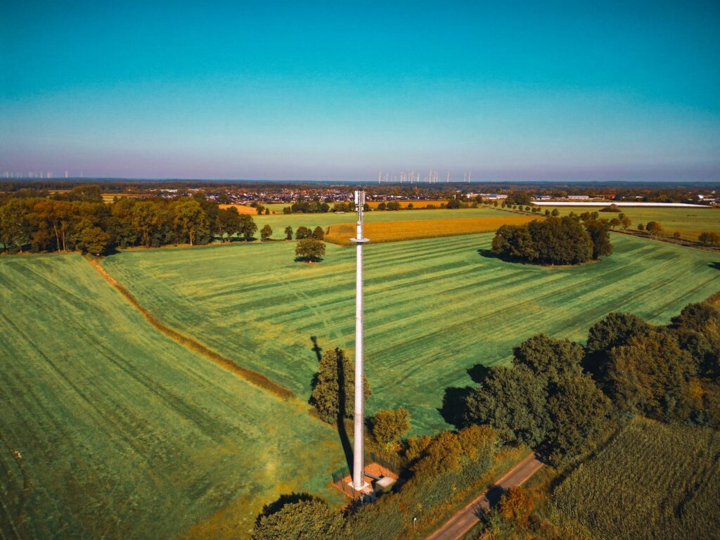
What Is Drone RTK? Accuracy, RTK vs PPK, and How to Choose a UAV Module
A standard drone usually knows where it is within a few meters. That is good enough for basic navigation, aerial photography, and return-to-home functions. It is not good enough when every image, flight line, crop row, inspection point, or survey coordinate must line up with a precise position in the real world. Drone RTK closes that gap by combining satellite observations with correction data from a known reference source. Once the receiver resolves the carrier-phase ambiguities and holds an RTK fixed solution, it can deliver centimeter-level positioning in real time.
Here’s the deal: centimeter-level positioning at the receiver does not automatically make every point in an orthomosaic, point cloud, digital surface model, or 3D reconstruction accurate to one centimeter. The completed job still depends on satellite geometry, correction-link quality, camera calibration, image overlap, shutter behavior, flight altitude, terrain, timestamp synchronization, antenna placement, processing settings, and independent field checks. This guide covers how drone RTK works, how it compares with PPK and ground control points, and which specifications actually matter when choosing a GNSS RTK receiver for a commercial or custom UAV.
Table of Contents
- 👉 What Is Drone RTK? The Quick Answer
- 👉 Why Standard Drone GNSS Is Not Centimeter-Accurate
- 👉 How Drone RTK Works
- 👉 Components of a Drone RTK System
- 👉 How Accurate Is Drone RTK?
- 👉 RTK vs PPK vs Ground Control Points
- 👉 RTK Drone Mapping Workflow
- 👉 How to Choose a UAV RTK Module
- 👉 RTK Module Specifications and Product Comparison
- 👉 Integrating RTK into a Custom UAV
- 👉 Common Drone RTK Failure Modes
- 👉 Industrial Applications of Drone RTK
- 👉 How to Validate Drone RTK Accuracy
- 👉 Conclusion and Selection Checklist
- 👉 Frequently Asked Questions
What Is Drone RTK? The Quick Answer
Drone RTK, or real-time kinematic positioning for unmanned aerial vehicles, is a GNSS technique that uses correction data from a known reference station or correction network to improve a drone’s real-time position from meter-level accuracy to centimeter-level accuracy under suitable operating conditions.
What does RTK mean?
RTK stands for real-time kinematic. “Real time” means the system applies correction data while the aircraft is operating. “Kinematic” means the receiver is built to maintain a precise positioning solution while moving, not just while sitting still on a survey point.
A typical RTK drone carries a multi-frequency GNSS rover receiver and an antenna with a clear view of the sky. It also needs a correction source and a communication link. Corrections may come from a local drone base station or a continuously operating reference station, usually called a CORS network. Depending on the hardware and the jobsite, that data may arrive through cellular internet and NTRIP, LoRa, telemetry radio, or another compatible link.
The corrected position can be sent to the flight controller for navigation, to a companion computer for autonomous operation, or to a payload controller that records accurate image-event coordinates. In mapping work, exposure timing matters just as much as position quality. If the camera fires at one moment and the system assigns a coordinate from another moment, the map can be wrong even though the GNSS receiver itself is working properly.
What RTK does not automatically guarantee
Look, there are several different accuracy numbers in play. RTK receiver accuracy, drone trajectory accuracy, camera exposure-center accuracy, and final map accuracy are related, but they are not interchangeable. A receiver may report an excellent antenna position while the finished map still contains errors from camera-trigger latency, an incorrect antenna-to-camera offset, rolling-shutter distortion, motion blur, weak photogrammetric geometry, or the wrong coordinate reference system.
That means a published specification such as 1 cm horizontal accuracy should be treated as receiver-level performance under suitable conditions. It is not an unconditional promise that every pixel, point, contour, or measured feature in the finished survey will be accurate to 1 cm.
Why Standard Drone GNSS Is Not Centimeter-Accurate
Autonomous drones normally calculate position from signals transmitted by satellite constellations such as GPS, BeiDou, Galileo, GLONASS, QZSS, and IRNSS. A standalone receiver works from those satellite signals without receiving precise corrections from a nearby or networked reference station.
Several error sources stack up in that process. They include satellite clock and orbital errors, ionospheric and tropospheric delays, receiver noise, limited satellite visibility, poor dilution of precision, antenna behavior, radio-frequency interference, and reflected signals. Reflections are a major concern around buildings, vehicles, metal roofs, towers, industrial machinery, and steep terrain. They produce multipath, where the antenna receives the direct satellite signal along with one or more delayed reflections.
Electrical integration can make or break the installation. In the shop, motors, electronic speed controllers, high-current power cables, transmitters, DC-to-DC converters, and poorly shielded electronics are all worth checking. Carbon-fiber structures can also block, reflect, or distort GNSS signals when the antenna is buried in the wrong part of the airframe.
Carrier-phase positioning
Conventional GNSS positioning relies heavily on ranging codes transmitted by the satellites. RTK also measures the phase of the GNSS carrier signal. Because the carrier wavelength is much shorter than the ranging-code scale, carrier-phase observations can support much finer positioning. The catch is that the receiver must first determine how many complete signal cycles exist between the satellites and the antennas.
That process is called integer ambiguity resolution. Until the receiver resolves those unknown cycles with enough confidence, it may report an RTK float solution instead of an RTK fixed solution. Fixed is the state operators want for precision work, but it has to be earned and maintained through clean observations and valid correction data.
Why a reference station helps
A reference receiver is installed over a known or accurately determined coordinate. The base and rover observe many of the same satellites at roughly the same time. Because the two receivers share several error sources, the system can estimate or reduce those common errors. The rover combines the correction stream with its own observations to calculate a more accurate position relative to the reference source.
RTK does not replace satellite navigation. It tightens satellite navigation by adding reference observations, carrier-phase processing, ambiguity resolution, and a live correction stream.
How Drone RTK Works
The RTK process step by step
- ⚙️ Satellite observation: The reference receiver and UAV rover track signals from multiple GNSS satellites and, ideally, more than one frequency band.
- ⚙️ Reference coordinate: The base station operates from a known coordinate, a carefully established coordinate, or an established correction network.
- ⚙️ Correction generation: The reference system compares its observations with its known position and generates correction information.
- ⚙️ Correction transmission: The corrections reach the UAV through LoRa, telemetry radio, 4G, an internet-connected ground station, or NTRIP.
- ⚙️ Carrier-phase processing: The rover combines incoming corrections with its own satellite observations.
- ⚙️ Ambiguity resolution: The receiver estimates and attempts to resolve the integer carrier-cycle ambiguities.
- ⚙️ Fixed solution: When ambiguity resolution succeeds with sufficient confidence, the receiver reports an RTK fixed position.
- ⚙️ Position output: The corrected result goes to the flight controller, payload controller, companion computer, or data logger through a supported interface and protocol.
RTK fixed, RTK float, and standalone GNSS
RTK fixed means the receiver has resolved the carrier-phase ambiguities. This is the state normally associated with centimeter-level positioning. To keep that fixed solution, the receiver must continue seeing a usable set of satellites and receiving valid corrections.
RTK float means the receiver is still estimating the ambiguities or has lost confidence in a previously fixed result. Float positioning may be better than ordinary standalone GNSS, but its accuracy is typically poorer and less predictable than fixed positioning.
Single, autonomous, or standalone positioning means the receiver does not currently have a usable RTK solution. It is calculating position from its own satellite measurements without a successfully resolved correction-based result.
An RTK-capable receiver is not guaranteed to operate at fixed accuracy for every second of a mission. Good UAV software should log solution status, correction age, satellite data, and timestamps. Logging only latitude, longitude, and altitude leaves out the evidence needed to judge whether those coordinates can be trusted.
Why dual-frequency GNSS matters
Dual-frequency reception, including combinations such as L1/L5 RTK, gives the receiver observations on more than one frequency. That can improve ionospheric-error estimation, speed up ambiguity resolution, and help maintain continuity when individual signals are weak or obstructed. Multi-constellation support also increases the number of satellites and improves the geometry available to the receiver.
Those features make a system more robust, but they are not magic. Dual-frequency hardware cannot eliminate severe multipath, poor antenna placement, dense foliage, urban obstruction, or electrical interference. The installation still matters just as much as the specification sheet.
Understanding “1 cm + 1 ppm”
The abbreviation ppm means parts per million. In an RTK accuracy specification, it represents a distance-dependent term tied to the baseline between the rover and the reference source. At a 1 km baseline, 1 ppm contributes roughly 1 mm. At 5 km, it contributes roughly 5 mm.
A horizontal specification of 1.0 cm + 1 ppm therefore contains a constant 1 cm term plus a baseline-related term. Keep the context straight: this is a receiver-positioning specification under stated or appropriate operating conditions. It is not a blanket accuracy guarantee for every point in a completed mapping deliverable.
Components of a Drone RTK System
1. UAV rover receiver
The rover tracks satellites, receives correction data, calculates the corrected position, and outputs position and status information. Important selection factors include supported frequencies, constellations, update rate, time to first fix, communication protocols, correction interfaces, weight, input voltage, power demand, and the receiver’s ability to hold a fixed solution in the intended environment.
2. GNSS antenna
The antenna needs a clear view of the sky and a stable orientation. Its location should limit obstruction, vibration, multipath, and interference from motors, power electronics, transmitters, and high-current wiring. Phase-center stability, antenna gain, ground-plane requirements, cable quality, connector quality, and the airframe material can all affect real performance.
An all-in-one antenna and receiver assembly reduces external cabling and may simplify UAV integration. That is useful, especially on a compact airframe, but it does not remove the need for thoughtful mounting and EMI control.
3. Local base station or CORS network
A local base station gives the operator direct control over the equipment, coordinate, correction link, and site setup. It is often the practical choice where cellular service is unavailable. The risk is straightforward: if the base coordinate is wrong, the entire project can be precisely wrong by the same amount.
A CORS or network RTK service reduces the need to deploy a local base. In exchange, the job depends on service coverage, credentials, cellular connectivity, correction compatibility, network latency, and the coordinate framework used by the provider.
4. Correction-data link
4G and NTRIP are practical when reliable internet access and an appropriate correction service are available. A direct LoRa or telemetry-radio connection can support local base-to-rover operation without depending on public cellular infrastructure.
Published radio range should always be treated as a best-case or test-condition number. Terrain, line of sight, antenna orientation, interference, airframe shadowing, transmit power, and configuration all affect what happens in the field. Frequency and power regulations also vary by jurisdiction, so a default 915 MHz setup must be checked against local spectrum rules before operation.
5. Flight controller, IMU, and complementary sensors
RTK provides globally referenced position. The inertial measurement unit supplies much higher-rate acceleration and angular-motion data between GNSS updates. A robust autonomous platform often combines GNSS with inertial estimation, barometric altitude, cameras, LiDAR, radar, or other sensors. VectorNav provides useful industry context on GNSS and inertial navigation, while HOKUYO is an established source of industrial ranging and detection technology.
Visual and inertial systems have their own failure modes. Poor lighting, low-texture surfaces, calibration errors, motion blur, vibration, or rapid motion can all reduce localization quality. The guide to visual-inertial odometry issues looks at these complementary localization problems in more detail.
How Accurate Is Drone RTK?
Under suitable satellite, correction, and installation conditions, an RTK fixed solution can provide centimeter-level positioning for the GNSS antenna. The important phrase is “for the GNSS antenna.” The finished drone-mapping product comes from a chain of measurements, transformations, timestamps, offsets, and processing decisions.
| Accuracy layer | What it describes | Major influences |
|---|---|---|
| Receiver solution | Position of the GNSS antenna phase center | Satellites, corrections, baseline, antenna quality, multipath |
| Drone trajectory | Estimated aircraft position through time | GNSS, IMU, filtering, latency, synchronization |
| Camera event position | Position assigned to an individual exposure | Trigger latency, lever arm, clock alignment, camera behavior |
| Mapping output | Orthomosaic, point cloud, DSM, contours, or 3D model | All prior factors plus camera calibration and processing quality |
Horizontal and vertical accuracy
Vertical GNSS accuracy is usually weaker than horizontal accuracy because satellite geometry provides less strength along the vertical axis. The HM-D20 and HM-D13, for example, publish horizontal accuracy of 1.0 cm + 1 ppm and vertical accuracy of 1.5 cm + 1 ppm. Those numbers describe module performance. They should not be presented as guaranteed orthomosaic, point-cloud, or elevation-model accuracy.
Factors affecting real-world drone RTK accuracy
- ⚙️ Number, signal quality, and geometry of tracked satellites
- ⚙️ Open-sky operation versus urban, tree-covered, or mountainous terrain
- ⚙️ Multipath from structures, vehicles, roofs, water, and machinery
- ⚙️ Accuracy of the local base-station coordinate
- ⚙️ Distance between the rover and the reference source
- ⚙️ Correction age, latency, packet loss, and format compatibility
- ⚙️ Percentage of the mission completed with an RTK fixed solution
- ⚙️ Camera focal-length and lens-distortion calibration
- ⚙️ Global-shutter or rolling-shutter behavior
- ⚙️ Flight altitude, ground sample distance, overlap, and image geometry
- ⚙️ Wind, vibration, aircraft attitude, image focus, and motion blur
- ⚙️ Camera-trigger synchronization and timestamp quality
- ⚙️ GNSS antenna-to-camera lever-arm compensation
- ⚙️ Coordinate system, geoid, ellipsoid, and datum configuration
RTK vs PPK vs Ground Control Points
| Method | When corrections are applied | Live link required | Primary advantage | Primary limitation |
|---|---|---|---|---|
| RTK | During the flight | Yes | Immediate corrected positions and precise live navigation | Depends on correction-link continuity |
| PPK | After the flight | No continuous link required | Can recover accurate positions despite in-flight link interruptions | Requires raw observations and post-processing |
| GCPs | During photogrammetric adjustment | No | Adds surveyed spatial constraints to the model | Requires placement, surveying, marking, and image identification |
Choose RTK when
RTK makes sense when precise live navigation matters, corrected camera positions are needed immediately, field turnaround must be fast, and a reliable base or network correction source is available. It can reduce the number of ground control points required for routine mapping, but independent checkpoints should still be used to verify the result.
Choose PPK when
PPK is a strong option when cellular or radio links are unreliable, the job can tolerate post-processing, and the system records compatible raw rover observations and event timestamps. Since the corrections are applied after the mission, PPK can recover precise image positions even when the live link was unavailable, weak, or intermittent.
Use ground control and checkpoints when
Ground control is appropriate when the project specification requires surveyed constraints, the terrain has substantial relief, camera calibration is uncertain, or the work carries contractual or regulatory accuracy requirements. A ground control point is included in the model adjustment. A checkpoint is deliberately withheld and used to test the completed output.
For demanding projects, a practical setup may combine all three tools: RTK for field efficiency, PPK-compatible logging for recovery, and independently surveyed checkpoints for objective verification. There is no prize for relying on one method when a redundant workflow reduces risk.
RTK Drone Mapping Workflow
Before the flight
- ✅ Confirm the required coordinate reference system and vertical datum.
- ✅ Verify the base-station coordinate or NTRIP correction service.
- ✅ Inspect antenna mounting, connectors, and cable security.
- ✅ Confirm adequate satellite tracking and correction reception.
- ✅ Wait for RTK fixed status before beginning a precision mission.
- ✅ Check correction age, latency, link strength, and data format.
- ✅ Verify camera-trigger timing and image-event recording.
- ✅ Survey independent checkpoints when validation is required.
During the flight
Monitor fixed, float, and standalone states instead of trusting a simple “RTK connected” indicator. That label may only confirm that a communication path exists. It does not prove that the rover has resolved ambiguities or that every exposure received a fixed coordinate. Operators should also watch satellite geometry, correction age, packet loss, battery voltage, flight path, image overlap, wind, and aircraft attitude.
After the flight
Review the GNSS and flight logs. Identify periods of float operation, correction loss, or suspicious position changes. Confirm that the correct coordinates are associated with the correct exposures. Apply the measured antenna-to-camera lever-arm offset, verify the datum and coordinate settings, and inspect image quality before starting photogrammetric processing.
After generating the orthomosaic, point cloud, or surface model, compare it with independent checkpoints. Report horizontal and vertical residuals, RMSE, maximum error, and the percentage of the mission completed in RTK fixed status. Save the base, rover, correction, camera-event, and mission logs. When a customer questions a result six months later, those records are what let the engineering team reconstruct what happened.
How to Choose a UAV RTK Module
Frequency and constellation support
Multi-frequency tracking is preferable for demanding UAV work because it gives the receiver a stronger observation set for ionospheric estimation and ambiguity resolution. Check the actual bands and constellations on the data sheet rather than relying on the broad marketing term “multi-GNSS.” The HM-D20 lists L1/L5 dual-frequency RTK and support for GPS, BeiDou, Galileo, QZSS, GLONASS, and IRNSS.
Horizontal and vertical accuracy
Look for separate horizontal and vertical specifications. Determine whether a ppm term is included, and ask which baseline, correction format, solution state, confidence level, and operating conditions apply. A clean data sheet should make it possible to distinguish fixed RTK performance from standalone GNSS performance.
Update rate and latency
A 10 Hz output provides up to ten position updates per second. That is enough for many mapping drones and mobile robots, especially when a flight controller fuses GNSS with a higher-rate IMU. Update rate is only part of the story. Engineers should also evaluate timestamp quality, end-to-end latency, serial bandwidth, processor loading, and estimator compatibility.
RTK time to first fix
A receiver may start tracking satellites well before it reaches an RTK fixed solution. The HM-D20 and HM-D13 both list an RTK time to first fix of 45 seconds. Actual initialization time can change with sky visibility, correction availability, baseline length, signal quality, multipath, movement, and whether the receiver starts from a favorable state.
Size, weight, and power
On a small UAV, installed mass affects endurance, center of gravity, payload capacity, and flight dynamics. The HM-D20 is listed at 38.2 g, measures Φ54.5 × 53 mm, and operates at 5 V ±0.5 V. The real installation mass also includes connectors, wiring, mounts, communication hardware, enclosure parts, and any voltage regulator required by the aircraft.
Protocols and electrical interfaces
Check NMEA support, vendor binary output such as UBX, connector type, serial voltage level, baud rate, raw observation availability, timing support, and flight-controller driver compatibility. Two devices can be physically connected and still be unable to communicate correctly. Pinouts, logic levels, message rates, and firmware support all need to match.
Correction-link options
Determine whether the deployment needs 4G/NTRIP, a CORS subscription, local LoRa, one-to-many rover networking, or offline PPK redundancy. The HM-D20 and HM-D13 list CORS/NTRIP support for their 4G option and a default 915 MHz LoRa option with a published communication range of up to 6 km. Actual range depends on terrain, antennas, interference, line of sight, configuration, transmit power, and local regulations.
Mechanical and environmental integration
Evaluate weather exposure, temperature, vibration, connector retention, cable strain relief, propeller airflow, EMI, and structural obstruction. Do not assume a product has an ingress-protection rating, shock qualification, or environmental certification unless that rating is explicitly published for the exact configuration being purchased.
RTK Module Specifications and Product Comparison
The HM-D20 and HM-D13 share several core RTK performance specifications, but they serve different integration priorities. The HM-D20 is the more direct UAV option because it combines antenna, positioning, and communication functions in a compact 38.2 g assembly. The HM-D13 is positioned more broadly for surveying, field systems, UGVs, USVs, autonomous outdoor equipment, and base-station-oriented deployments.
HM-D20 All-in-One RTK GNSS Helical Antenna Module for Drone
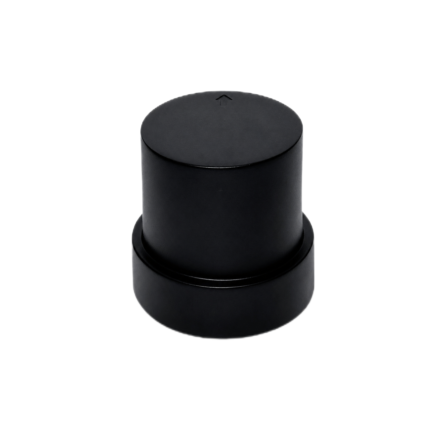
The HM-D20 is a compact L1/L5 dual-frequency GNSS RTK module designed for UAVs, autonomous vehicles, robotics, and survey mapping. It integrates the antenna, positioning receiver, and correction communication functions into one 38.2 g device. For a custom aircraft, that all-in-one layout can simplify packaging and reduce the external antenna cabling that would otherwise need to be routed and secured.
The receiver lists a 10 Hz maximum update rate, a 45-second RTK time to first fix, 200 tracking channels, and support for GPS, BeiDou, Galileo, QZSS, GLONASS, and IRNSS. Correction options include 4G for CORS/NTRIP and a default 915 MHz LoRa configuration. The LoRa implementation supports one base station communicating with one or multiple rovers, with a listed maximum of 4096 rovers.
| Positioning capability | L1/L5 dual-frequency RTK |
|---|---|
| Horizontal accuracy | 1.0 cm + 1 ppm |
| Vertical accuracy | 1.5 cm + 1 ppm |
| Maximum update rate | 10 Hz |
| RTK time to first fix | 45 s |
| 4G version | CORS/NTRIP |
| LoRa default frequency | 915 MHz |
| Published LoRa range | Up to 6 km |
| LoRa networking | One base station to one or multiple rovers |
| Maximum number of rovers | 4096 |
| Satellite systems | GPS, BeiDou, Galileo, QZSS, GLONASS, IRNSS |
| Tracking channels | 200 |
| Cold start / hot start | 28 s / 1 s |
| Antenna system gain | 40 dB |
| Dimensions / weight | Φ54.5 × 53 mm / 38.2 g |
| Operating voltage | 5 V ±0.5 V |
| Data and interface | 8-pin / NMEA / UBX |
| Magnetometer | QMC5883L, SCL/SDA |
View Product Details & Pricing ➔
HM-D13 RTK GNSS Receiver for UGV, USV, and Field Navigation
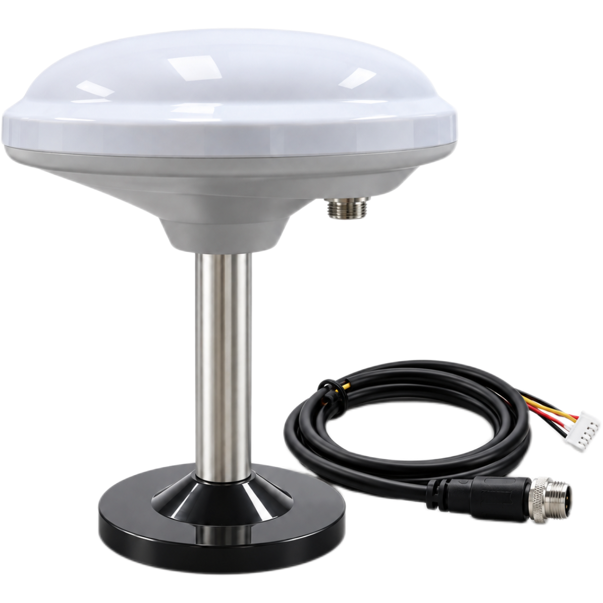
The HM-D13 is a multiband GNSS RTK system designed for surveying, field mapping, agricultural machinery, outdoor robots, UGVs, USVs, drones, and other autonomous platforms. It combines antenna, positioning, and communication functions and supports one-to-many rover networking.
Like the HM-D20, it publishes L1/L5 dual-frequency RTK capability, horizontal accuracy of 1.0 cm + 1 ppm, vertical accuracy of 1.5 cm + 1 ppm, a 10 Hz maximum update rate, and a 45-second RTK time to first fix. The supplied mechanical specification of Φ152 × 67.9 mm and 550 g applies to the base station, so anyone considering aircraft use should verify the exact rover configuration and total installed mass before designing the mount.
The HM-D13 product information also describes operation in demanding outdoor conditions and lists an operating temperature range of -40°C to 85°C. As always, verify the environmental requirements and exact purchased configuration rather than assuming an unlisted certification or protection rating.
| Positioning capability | L1/L5 dual-frequency RTK |
|---|---|
| Horizontal accuracy | 1.0 cm + 1 ppm |
| Vertical accuracy | 1.5 cm + 1 ppm |
| Maximum update rate | 10 Hz |
| RTK time to first fix | 45 s |
| 4G version | CORS/NTRIP |
| LoRa default frequency | 915 MHz |
| Published LoRa range | Up to 6 km |
| LoRa networking | One base station to one or multiple rovers |
| Maximum number of rovers | 4096 |
| Satellite systems | GPS, BeiDou, Galileo, QZSS, GLONASS, IRNSS |
| Cold start / hot start | 28 s / 1 s |
| Antenna system gain | 40 dB |
| Dimensions / weight | Φ152 × 67.9 mm / 550 g (base station) |
| Operating voltage | 5 V |
| Data and interface | 5-pin XH2.54 / NMEA / UBX |
| Listed operating temperature | -40°C to 85°C |
View Product Details & Pricing ➔
Direct comparison
| Specification | HM-D20 | HM-D13 |
|---|---|---|
| RTK capability | L1/L5 dual-frequency | L1/L5 dual-frequency |
| Accuracy | 1.0 cm + 1 ppm horizontal; 1.5 cm + 1 ppm vertical | 1.0 cm + 1 ppm horizontal; 1.5 cm + 1 ppm vertical |
| Update rate | 10 Hz | 10 Hz |
| Tracking channels | 200 | Not specified in supplied data |
| Mechanical specification | Φ54.5 × 53 mm / 38.2 g | Φ152 × 67.9 mm / 550 g for base station |
| Interface | 8-pin / NMEA / UBX | 5-pin XH2.54 / NMEA / UBX |
| Best-fit use | Compact UAVs, custom drones, mapping platforms, and mobile robots | Field systems, base stations, UGVs, USVs, surveying, and outdoor robotics |
Integrating RTK into a Custom UAV
Mechanical mounting
Mount the GNSS antenna where the airframe does not block its view of the sky. Keep reasonable separation from motors, ESCs, power distribution boards, high-current battery wiring, and high-power transmitters. Carbon-fiber plates can attenuate or reflect signals, so placing the antenna above the main structure is often the better arrangement when the mechanical design allows it.
The mount should be rigid enough to preserve a stable antenna orientation and a repeatable lever-arm measurement. At the same time, it should control excessive vibration. Connector retention and cable strain relief deserve special attention on an aircraft because propeller vibration, transport, and repeated handling can loosen marginal connections.
Electrical integration
For the HM-D20, design around the specified 5 V ±0.5 V input. Verify regulator output while the motors are under maximum expected load, not just while the aircraft sits idle on the bench. Check grounding, logic-level compatibility, pinout, reverse-polarity protection, noise filtering, and connector retention. Obtain current-consumption requirements from the applicable documentation instead of designing around a guessed value.
Flight-controller compatibility
Confirm that the flight controller or companion computer can parse NMEA, UBX, or whichever data format the installation requires. Integration testing should verify baud rate, update rate, coordinate output, altitude reference, satellite count, fixed/float status, correction age, and recovery after a temporary interruption.
Some systems deliver correction data to a GNSS receiver and perform the RTK calculation onboard. Other architectures use an integrated receiver that outputs the completed position solution. The software, wiring, message routing, and correction path must match the selected operating mode.
Time synchronization and camera triggering
Photogrammetry requires the coordinate to be associated with the exact exposure time. Camera-trigger latency, flight-controller clock drift, GNSS timestamps, event markers, PPS capability where available, and rolling-shutter timing can all influence the result.
Here is a useful shop-floor calculation. At an aircraft speed of 15 m/s, a 100 ms timestamp error equals about 1.5 m of travel. A receiver can be accurate to centimeters while the assigned image position is wrong by more than a meter. That is why synchronization can be every bit as important as static GNSS accuracy. The measured vector between the antenna phase center and the camera perspective center must also be applied as a lever-arm offset.
Multi-sensor integration
RTK provides global position, while inertial, visual, and ranging sensors can provide attitude, short-term motion, terrain distance, and obstacle information. For short-range ranging considerations, review the MRP HM-LD1 dToF LiDAR distance test report and the comparison of dToF HM-LD1 vs Sony AS-DT1. These sensors complement RTK; they do not replace globally referenced GNSS positioning.
Common Drone RTK Failure Modes and Troubleshooting
| Symptom | Likely causes | Checks and actions |
|---|---|---|
| Receiver remains in float | Multipath, poor sky view, weak corrections, long baseline | Move to open sky, verify correction source, inspect satellite geometry |
| Fixed-to-float transitions | Obstruction, EMI, packet loss, vibration | Review logs, reposition the antenna, inspect power and correction links |
| Map is consistently shifted | Incorrect base coordinate, CRS, datum, or transformation | Verify base setup, coordinate reference, geoid, and ellipsoid treatment |
| Weak elevation accuracy | Vertical geometry or datum mismatch | Verify vertical reference and compare against surveyed checkpoints |
| Good GNSS but blurred mapping output | Camera, wind, focus, shutter, or flight-planning issue | Check shutter speed, focus, image overlap, and aircraft motion |
| Position jumps near structures | Multipath or signal blockage | Increase clearance from buildings, roofs, vehicles, and machinery |
| Link works on the ground but not in flight | Antenna orientation, airframe shadowing, range, or interference | Conduct airborne range tests and review antenna placement |
| Image positions lag behind exposures | Trigger or timestamp delay | Measure latency and configure accurate event synchronization |
Detailed logging is essential. Troubleshooting turns into guesswork when the system stores coordinates but leaves out RTK status, correction age, timestamps, satellite information, and image-event data. In the shop, a complete log is often the difference between fixing the root cause and replacing good hardware for no reason.
Industrial Applications of Drone RTK
Surveying and mapping
RTK supports direct georeferencing for orthomosaics, point clouds, contour maps, topographic surveys, stockpile measurements, and construction-progress monitoring. An aircraft should not be called survey grade simply because an RTK receiver is bolted to it. The complete workflow and the independently measured output determine whether the system meets the project requirement.
Precision agriculture
Common applications include field-boundary mapping, crop scouting, repeatable flight paths, multispectral surveys, drainage analysis, and coordination with autonomous agricultural equipment. Accurate repeatability can help teams compare conditions across multiple missions, provided the coordinate systems, base references, sensors, and processing settings remain consistent.
Infrastructure inspection
RTK can improve repeatable positioning for powerline, bridge, tower, solar, roof, and corridor inspections. It can help the aircraft or payload return to consistent coordinates, but close-range operation still requires obstacle awareness, appropriate flight planning, and a safe response to GNSS degradation.
Construction and mining
Construction and mining teams use RTK drone mapping for earthworks, cut-and-fill analysis, stockpile volumes, progress surveys, and comparison with CAD or GIS data. Coordinate-system consistency across the UAV, base station, machine-control system, engineering design, and processing software is essential. A datum mismatch can create a clean-looking deliverable that is unusable in the field.
Autonomous UAV and robotics navigation
High-accuracy global positioning can support repeatable routes, docking approaches, fleet coordination, UGV navigation, USV operations, and outdoor field robotics. In obstructed or safety-critical environments, RTK should be fused with inertial, visual, LiDAR, or other localization methods rather than treated as the only navigation source.
How to Validate Drone RTK Accuracy
Use independent checkpoints
Spread checkpoints across the project area instead of clustering them near takeoff. Include the center, edges, high and low elevations, and areas with different terrain or vegetation. Survey those checkpoints with a method that provides enough accuracy for the project’s acceptance criteria.
Report more than one number
A professional accuracy report should include horizontal RMSE, vertical RMSE, mean bias, maximum residual, checkpoint count, individual checkpoint errors, survey method, coordinate system, vertical datum, and RTK fixed percentage. RMSE is useful, but it can hide localized outliers. Individual residuals matter on higher-risk projects.
Repeatability is not absolute accuracy
Repeatability describes how closely repeated measurements agree with one another. Absolute accuracy describes how closely those measurements match the correct real-world coordinates. A drone can produce highly repeatable models that are all shifted because the base coordinate, datum, geoid, or transformation is wrong. Repeated flights alone do not prove absolute accuracy.
Recommended commissioning test
- ⚙️ Fly an open-sky test site containing independently surveyed checkpoints.
- ⚙️ Confirm RTK fixed status across the mission.
- ⚙️ Process the data with the intended production workflow.
- ⚙️ Compare horizontal and vertical checkpoint residuals.
- ⚙️ Repeat the mission at another time or under different satellite geometry.
- ⚙️ Introduce a controlled correction-link interruption.
- ⚙️ Verify behavior during fixed, float, standalone operation, and recovery.
- ⚙️ Document the results as the system’s integration baseline.
Conclusion: Drone RTK Selection Checklist
Drone RTK combines multi-frequency satellite observations with reference corrections to improve real-time UAV positioning from meter-level to centimeter-level performance under suitable conditions. Its main advantages are precise live navigation, more accurate image geotagging, repeatable operation, and reduced dependence on dense ground control.
The limitations are just as important. Performance depends on satellite visibility, correction quality, antenna installation, coordinate management, timing, and software integration. The final map must be checked independently rather than accepted on the strength of a receiver specification.
- ✅ Does the module support the required GNSS frequencies and constellations?
- ✅ Are horizontal and vertical accuracy specified separately?
- ✅ Can it maintain an RTK fixed solution in the intended environment?
- ✅ Is the total installed mass suitable for the aircraft?
- ✅ Does the power input match the UAV power architecture?
- ✅ Are NMEA, UBX, or the required raw observations available?
- ✅ Is the maximum update rate sufficient for the platform?
- ✅ Can corrections arrive through NTRIP, CORS, LoRa, or the intended radio?
- ✅ Can the antenna be installed away from obstruction and EMI?
- ✅ Can the system record fixed/float status and correction age?
- ✅ Can camera events be timestamped accurately?
- ✅ Will the completed system be tested against independent checkpoints?
- ✅ Does the radio configuration comply with local regulations?
For lightweight custom UAV integration, explore the HM-D20 all-in-one RTK GNSS module. For field systems, base-station use, UGVs, USVs, and broader outdoor positioning applications, review the HM-D13 RTK GNSS receiver.
Frequently Asked Questions About Drone RTK
How accurate is RTK drone mapping in real-world conditions?
Should I choose RTK, PPK, or ground control points for UAV mapping?
Can I add RTK to a mini drone or custom UAV?
Does an RTK drone always need its own base station?
What is the difference between RTK fixed and RTK float?
Is NTRIP better than LoRa for an RTK drone?
Is a 10 Hz GNSS update rate enough for a UAV?
Will RTK work near buildings, trees, or power infrastructure?
📚 References & Further Reading
-
- Industry Standard: VectorNav GNSS and inertial navigation resources
- Industry Standard: HOKUYO industrial sensing resources
- Related Guide: Explore Visual-Inertial Odometry Issues