


How to Choose an Inertia Sensor for Robotics, Drones, and Industrial Automation
Here’s the deal: choosing an inertia sensor is not as simple as buying the smallest module or picking the one with the highest advertised output rate. In robotics, drones, and industrial automation, gyro bias instability, accelerometer stability, bandwidth, temperature behavior, vibration sensitivity, interface compatibility, and mounting accuracy all affect whether the machine can maintain reliable attitude, localization, and motion control. A unit that looks excellent on a quiet laboratory bench can become noisy, unstable, or downright troublesome once it is bolted to a robot arm, autonomous vehicle, UAV, or industrial machine.
This guide approaches inertia-sensor selection from both an engineering and purchasing standpoint. It explains how inertial measurement units work, which specifications deserve close attention, how to compare gyroscope and accelerometer errors, and how to match a sensor to a real application. It also uses the Industrial High Precision IMU HM-G12 as a practical example, including its published performance, electrical interface, mechanical dimensions, operating temperature range, and integration considerations.
Table of Contents
- 👉 What Is an Inertia Sensor?
- 👉 How an Inertia Sensor Works
- 👉 Key Inertia Sensor Specifications
- 👉 Match the Sensor to the Application
- 👉 Mounting and System Integration
- 👉 Common Inertia Sensor Errors and How to Reduce Them
- 👉 Industrial High Precision IMU HM-G12 Specifications
- 👉 Inertia Sensor Selection Checklist
- 👉 Choose the Inertia Sensor That Matches the Motion Problem
- 👉 Frequently Asked Questions

View Product Details & Pricing ➔
What Is an Inertia Sensor?
Inertia sensor versus inertial sensor
An inertia sensor measures motion associated with linear acceleration, rotation, or both. Buyers often use the phrase “inertia sensor,” although “inertial sensor,” “inertial measurement unit,” and “IMU” are the more established engineering terms. A typical 6-axis IMU combines three gyroscope axes and three accelerometer axes. Depending on the product, embedded electronics may also provide signal conditioning, calibration compensation, digital filtering, health monitoring, diagnostics, and a communication interface for the host controller.
Look closely at what the manufacturer actually supplies. The word “inertial” does not guarantee that a module includes every function required for navigation. Some IMUs output calibrated angular-rate and acceleration measurements. Others calculate attitude internally and may provide roll, pitch, or yaw estimates. Magnetometers, GNSS receivers, pressure sensors, and absolute position outputs are separate capabilities unless the manufacturer explicitly says otherwise. Start any comparison by defining the required output data instead of relying on the IMU label.
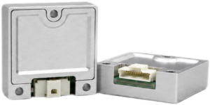
a short-flex design and a long-flex design for different robotics and UAV d…
What an inertia sensor measures
A gyroscope measures angular velocity around one or more axes, usually expressed in degrees per second or radians per second. An accelerometer measures specific force along one or more axes, usually expressed in g or meters per second squared. When a machine is stationary or moving slowly, the gravity vector observed by the accelerometer can help estimate roll and pitch. Once the platform begins accelerating, braking, vibrating, or taking an impact, the accelerometer responds to gravity and machine dynamics at the same time. The sensor cannot cleanly separate those effects without additional estimation.
An IMU does not directly measure absolute position. Orientation, velocity, and position must be calculated by integrating measured angular rate and acceleration over time. The catch is that sensor bias and noise are integrated too. Small errors therefore grow into drift. That is why practical systems often combine an IMU with wheel encoders, GNSS, cameras, LiDAR, joint encoders, or another external reference.
In the shop, this distinction matters. A machine builder may expect an IMU to provide a trustworthy position indefinitely, only to discover that the position estimate begins wandering after a short period. That is not necessarily a defective sensor. It is a fundamental property of inertial navigation. Better bias performance slows the drift, but external observations are normally required to constrain it over longer operating periods.
Why inertia sensors matter in automation
Inertial sensing supports flight stabilization, robot attitude estimation, mobile-platform heading, gimbal control, machine monitoring, dead reckoning, motion compensation, and vibration analysis. A robotic arm can use local inertial measurements to observe end-effector movement or structural vibration. AGVs and AMRs can use an IMU to bridge short gaps between localization updates and identify movement that does not agree with wheel-encoder predictions. UAV flight controllers depend on rapid angular-rate and acceleration measurements to remain stable.
In modern sensor-based perception and autonomous systems, inertial sensors and LiDAR handle different but complementary jobs. An IMU observes rapid local motion without requiring external landmarks. LiDAR measures surrounding geometry and can provide environmental constraints for localization. Combining them can produce a more robust estimate than either sensor can provide by itself.
How an Inertia Sensor Works
MEMS gyroscopes
A microelectromechanical systems gyroscope detects angular movement using microscopic vibrating structures. When the sensor rotates, Coriolis forces alter the movement of those structures. Electronic circuitry measures the resulting displacement and converts it into angular-rate data for the X, Y, or Z axis.
Real gyroscopes never produce a perfectly clean zero while sitting still. Their output includes bias offset, random noise, temperature effects, scale-factor error, axis misalignment, and cross-axis sensitivity. Bias deserves special attention because a nearly constant angular-rate error turns into steadily increasing orientation error after integration. Angular random walk describes another form of growing orientation uncertainty caused by gyro noise.
Temperature changes the mechanical and electrical behavior inside a MEMS device. Industrial IMUs often use factory calibration tables or compensation models to reduce these effects. Even then, engineers should review startup behavior, warm-up time, thermal transients, and the exact conditions under which the published specifications were measured. A sensor mounted beside a motor drive may behave differently from the same sensor resting on an air-conditioned bench.
MEMS accelerometers
A MEMS accelerometer uses a small proof mass suspended by microscopic structures. Applied specific force moves the mass, and electronics measure that displacement. A three-axis accelerometer reports specific force along its X, Y, and Z axes. Those measurements include the apparent effect of gravity as well as dynamic acceleration from the machine.
Important accelerometer characteristics include range, bias, scale factor, noise, velocity random walk, bandwidth, vibration sensitivity, and shock tolerance. Bias is especially important in dead-reckoning applications. A small acceleration error integrates into a growing velocity error, and that velocity error is integrated again into an even larger position error. A unit that appears stable during a five-minute bench test may still be unsuitable for extended inertial navigation.
From raw measurements to usable motion data
- ⚙️ MEMS sensing elements generate raw signals related to angular movement and specific force.
- ⚙️ Analog and digital electronics amplify, digitize, and condition those signals.
- ⚙️ Calibration data corrects known bias, scale-factor, axis-alignment, and temperature effects.
- ⚙️ An embedded MCU applies compensation, filtering, diagnostics, and output formatting.
- ⚙️ The communication interface sends measurements to a robot controller, flight controller, PLC, or industrial computer.
- ⚙️ The host system uses the measurements for estimation, control, logging, monitoring, or sensor fusion.
Bandwidth and output rate describe different portions of that measurement chain. The HM-G12 lists 200 Hz gyroscope and accelerometer bandwidth together with a 1000 Hz output rate in its product summary. The 200 Hz bandwidth describes the physical response range of the sensor. The 1000 Hz rate describes how often processed data can be delivered to the host. A 1000 Hz output rate does not create 1000 Hz of independent physical measurement bandwidth.
A high output rate can still be valuable. It can improve control-loop timing, make interpolation easier, and give the estimator more frequent updates. However, sample timing, filter delay, packet latency, synchronization, and aliasing still have to be managed. If those details are ignored, a fast interface can simply deliver delayed or contaminated data more often.
Key Inertia Sensor Specifications
Gyroscope range
Gyroscope range defines the largest angular velocity the sensor can measure without saturating. A narrow range may provide finer effective resolution, while a wider range is necessary for aggressive UAV maneuvers, high-speed machinery, impacts, or rapid robotic motion. The correct range should exceed the highest expected angular rate with reasonable margin for abnormal but credible events.
Before selecting a sensor, determine both normal and peak platform rates. Consider whether mechanical shock could produce brief rotational spikes and what happens to the estimator if the data clips. The supplied HM-G12 information does not state a gyroscope measurement range. That value should be confirmed in current manufacturer documentation rather than inferred from bandwidth, bias, or accelerometer specifications.
Gyro bias instability
Gyro bias instability describes slow variation in the apparent zero-rate output over time. Lower bias instability generally supports better attitude propagation while an external reference is unavailable. It matters in mobile robots, UAVs, gimbals, and navigation systems that must maintain orientation between camera, LiDAR, GNSS, landmark, or encoder updates.
The HM-G12 specification table lists gyro bias instability as ≤ 1.4°/h. Its product summary separately describes 1.4°/h as typical performance. Keep those qualifiers intact when comparing the product. A typical value and a guaranteed upper limit are not automatically the same thing. Purchasing decisions should reference the current controlled datasheet and the associated test conditions.
Angular random walk
Angular random walk quantifies the effect of gyro noise on integrated angular uncertainty. The HM-G12 lists angular random walk of ≤ 0.15°/√h. A lower figure is useful for short-term attitude propagation, stabilization, inertial navigation, and motion tracking during temporary loss of visual or satellite references.
Do not judge a gyro from angular random walk alone. Filter configuration, sampling behavior, mechanical vibration, bandwidth, temperature, and estimator design all affect the result at system level. Two products with similar headline numbers can perform very differently when mounted near motors, gearboxes, propellers, or flexible structures.
Bias stability and orthogonality error
Bias stability describes how consistently the sensor offset remains under defined conditions. The HM-G12 gyroscope specification lists bias stability of ≤ 4°/h. Engineers should ask how the manufacturer distinguishes this value from bias instability and what averaging period, temperature condition, warm-up state, and test method apply.
Orthogonality error describes how far the sensing axes deviate from an ideal 90-degree relationship. The HM-G12 lists gyroscope orthogonality error of ≤ 0.05°. Its product summary also uses the phrase “gyro cross-axis coupling” with a value of ≤ 0.05°. Those terms should not be treated as interchangeable without checking the manufacturer’s definitions. Sensor-axis geometry, installation angle, structural flex, and software coordinate transforms can all contribute to cross-axis error.
Accelerometer range
The HM-G12 provides a ±16 g accelerometer range. The selected range must cover normal acceleration, vibration, shocks, impacts, and expected transient events without clipping. Saturated accelerometer data can corrupt attitude estimation and make velocity or position calculations unreliable.
On the other hand, choosing much more range than needed can reduce effective low-level resolution, depending on the sensor architecture and output format. The practical target is enough headroom without throwing away useful measurement quality. UAV launches, hard landings, robot collisions, gearbox vibration, wheel impacts, and industrial handling events should all be considered.
Accelerometer bias instability and stability
The HM-G12 lists accelerometer bias instability of 0.016 mg and accelerometer bias stability of 0.055 mg. These values matter because constant or slowly varying acceleration errors accumulate in calculated velocity and position. The longer a platform operates without an external reference, the more consequential those errors become.
For dead reckoning, compare bias behavior alongside temperature compensation, velocity random walk, scale factor, vibration response, and estimator design. A system receiving frequent external corrections may work acceptably with a less precise accelerometer. A system expected to navigate independently for longer intervals usually needs stronger inertial performance and better characterization.
Bandwidth and output rate
The published HM-G12 values include 200 Hz gyroscope bandwidth, 200 Hz accelerometer bandwidth, and a 1000 Hz output rate. Bandwidth describes the frequency range over which physical movement is measured. Output rate describes how frequently digital data is sent to the host.
Look beyond those two numbers. Review anti-alias filtering, selectable digital filters, group delay, packet latency, timestamp precision, synchronization inputs, and clock stability. Filtering can reduce noise, but every filter carries a tradeoff. Strong filtering often adds phase delay, and that delay may become a problem in a fast flight-control or stabilization loop.
Temperature performance
The HM-G12 has a specified operating temperature range of -40°C to 85°C and the same listed storage temperature range. The supplied product information states that each module is factory calibrated across the full operating range. This calibration is intended to reduce bias and scale-factor changes caused by temperature.
For high-accuracy or safety-related machinery, request details about the calibration method, acceptance limits, startup behavior, thermal-transient response, and test conditions. A module that passes a steady-state chamber test may still need careful validation next to a processor, battery, motor, heater, or sealed enclosure. Local sensor temperature can differ substantially from the room or outdoor air temperature.
Match the Sensor to the Application
Robotics and robotic arms
Robotic systems expose sensors to vibration from motors, gearboxes, bearings, cable carriers, and structural movement. An IMU mounted on an end effector experiences different acceleration from one mounted near the robot base. Rotational movement creates tangential and centripetal acceleration, and those terms change with the sensor’s distance from the axis of rotation.
Important selection factors include bias stability, usable bandwidth, communication latency, cable routing, connector retention, and repeatable mechanical alignment. Calibration must account for the actual installed orientation. For precision work, test the sensor over the complete robot trajectory rather than relying on stationary noise measurements.
In the shop, pay particular attention to cable forces. A stiff or poorly restrained cable can tug on a small IMU enclosure and create movement between the sensor and its mounting surface. That relative motion can appear as a genuine machine event. Proper strain relief is part of the measurement system, not an afterthought.
AGVs and AMRs
AGVs and AMRs use inertial measurements for heading estimation, wheel-slip detection, dead reckoning, and continuity between external localization updates. Low-speed platforms can be surprisingly sensitive to gyro drift because small heading errors build over long operating periods. Floor joints, ramps, payload changes, wheel wear, and curb impacts add dynamic conditions that should be represented during testing.
An IMU can complement LiDAR-based localization and mapping, wheel encoders, cameras, and GNSS. The inertial sensor provides rapid motion observations, while external perception limits long-term drift. A system can also combine inertial data with a 3D depth camera such as the P008G when depth perception is part of the navigation architecture.
Drones and UAVs
Drone IMUs need fast attitude response, appropriate angular-rate range, low latency, predictable timing, low weight, and strong resistance to vibration. Motors and propellers can generate narrow-band vibration and excite structural resonances in the frame. Those effects contaminate both gyroscope and accelerometer measurements. Temperature can also change rapidly because of altitude, airflow, sunlight, battery heating, and onboard electronics.
The HM-G12’s 14 g weight, 30 mm × 30 mm × 10.6 mm dimensions, listed 1000 Hz output rate, and ±16 g accelerometer range are relevant starting points for a UAV evaluation. Those specifications alone do not prove suitability for every airframe. The module must be validated with the intended propellers, motors, flight controller, filtering, power system, control-loop settings, and mounting arrangement.
Industrial automation and machinery
Industrial inertia sensors can support conveyor monitoring, gantry movement, platform leveling, mobile equipment, motion compensation, and machine-condition analysis. In these environments, environmental durability and lifecycle support may matter as much as laboratory noise performance.
Buyers should evaluate calibration traceability, connector reliability, electromagnetic compatibility, protocol documentation, firmware control, long-term availability, and technical support. Confirm the temperature at the actual sensor location rather than relying on general room temperature. Motors, drives, processors, and enclosed electronics can create local hot spots that are not obvious during initial design.
Camera stabilization and payload systems
Stabilized cameras and payloads require low gyro noise, stable bias, low communication latency, rigid mounting, and accurate alignment between the sensor and optical axes. Timing consistency is critical. Even an accurate angular-rate measurement can produce poor compensation if the data arrives late or is paired with the wrong image timestamp.
Mechanical flex between the IMU and payload creates relative movement that the sensor cannot distinguish from intended platform movement. Test the actual camera, lens, gimbal, cabling, and payload mass. A lightweight test fixture may not reproduce the resonances of the finished assembly.
Mounting and System Integration
Mount the sensor rigidly
An inertia sensor should be attached to the structural reference whose movement must be measured. Loose fasteners, flexible brackets, unsupported sheet metal, and untested adhesive mounts can introduce resonances or relative movement. When that happens, the sensor reports the behavior of its bracket instead of the intended platform.
The HM-G12 product information identifies screw mounting, a 10-pin connector, and a compact 30 mm × 30 mm × 10.6 mm package. Control mounting torque, fastener type, contact-surface flatness, and cable strain. Excessive mechanical stress can also affect sensor behavior, particularly if the enclosure or underlying board is distorted during installation.
Align the sensing axes
The host software must know the exact relationship between the sensor axes and the coordinate system used by the robot, vehicle, payload, or flight controller. Even a small mounting rotation can create substantial cross-axis error during strong acceleration or rapid movement.
- ⚙️ Identify the X, Y, and Z directions from the current controlled mechanical drawing.
- ⚙️ Define the coordinate convention used by the host software and estimator.
- ⚙️ Confirm whether each system uses a right-hand or left-hand convention.
- ⚙️ Perform boresight or extrinsic calibration when the accuracy requirement calls for it.
- ⚙️ Store the verified mounting orientation in controlled configuration data.
Mount near the center of rotation when appropriate
For mobile vehicles and many UAVs, installation near the body reference point or center of rotation can reduce lever-arm effects and simplify motion modeling. A sensor mounted far from that point experiences additional acceleration whenever the platform rotates. That acceleration is physically real, but it complicates the estimator if the offset is unknown or ignored.
The correct location depends on the job. An IMU near a robot end effector may intentionally measure local movement, while a navigation IMU is generally mounted close to the vehicle reference point. Measure any significant offset and include it in the system model where necessary.
Electrical integration
The HM-G12 lists UART ×1 as its default external data interface, an input voltage of DC 5 ± 0.5 V, operating current of ≤ 31 mA, and a 10-pin connector with a 3.3 V digital signal level. Supply voltage and communication logic voltage are separate requirements. A controller may provide 5 V power while its UART pins still need to be compatible with 3.3 V signaling.
Before connecting the module, verify the pinout, polarity, ground reference, UART voltage, packet structure, baud rate, startup sequence, cable length, shielding, and connector-retention requirements against current integration documents. Do not guess at a baud rate or pin assignment. Motors, relays, variable-frequency drives, and switching power supplies should be active during electrical-noise testing.
Common Inertia Sensor Errors and How to Reduce Them
Bias drift
Sensor bias changes with temperature, time, supply conditions, mechanical stress, aging, and normal device behavior. Factory calibration and temperature compensation can reduce drift, but they do not eliminate the need for system-level estimation. Warm-up routines, stationary bias estimation, and periodic correction from external references can materially improve practical performance.
Navigation systems commonly fuse inertial measurements with GNSS, cameras, wheel odometry, encoders, or LiDAR. Each source offers different observability and failure characteristics. Industrial LiDAR manufacturers such as Hesai Technology provide complementary perception hardware, but the external sensor must be synchronized and calibrated correctly before it can constrain inertial drift.
Vibration and resonance
Vibration can increase noise, create aliasing, excite resonances, and produce vibration-rectification effects. Improvised soft mounting is not always the answer. It may attenuate one frequency while amplifying another, and it can introduce phase delay or relative movement. The mounting strategy should be based on measured vibration data rather than guesswork.
Identify dominant frequencies, compare them with sensor bandwidth and control-loop behavior, and review the delay introduced by filtering. Test across motor speed, payload, flight condition, and machine operating mode. A laboratory shaker can be useful, but it may not reproduce every structural resonance or cable-coupling path found on the finished machine.
Axis misalignment and cross-axis coupling
Errors can come from sensor-axis orthogonality, installation angle, scale-factor mismatch, structural flex, or sensitivity to motion on another axis. Software calibration can reduce stable geometric errors. It cannot fully correct a loose bracket or a structure that bends differently as the load changes.
A controlled installation process should define mounting datums, fastener conditions, orientation tolerances, and calibration steps. Dynamic testing should include combined-axis movement. Single-axis bench tests often miss the cross-axis behavior that appears during real machine operation.
Electrical noise and communication errors
Ground loops, motor EMI, switching regulators, poor decoupling, long unshielded cables, and loose connectors can corrupt an otherwise capable sensor. Digital failures may appear as UART framing errors, dropped packets, incorrect byte order, stale data, incomplete startup, or intermittent resets.
Timing failures can be just as damaging as corrupted values. A valid measurement associated with the wrong control cycle can degrade stabilization and state estimation. Monitor packet sequence, timestamps, latency, error detection, and recovery behavior under realistic electrical loads.
Poor calibration and insufficient validation
A practical validation program should include more than a quick stationary test. At minimum, perform a stationary gyro-bias check, a static six-position accelerometer test, dynamic comparison against an external reference, vibration testing with operating motors, long-duration drift measurement, and communication stress testing. Add thermal cycling or chamber testing when the application spans a broad temperature range.
- ⚙️ Run the sensor long enough to observe startup and warm-up behavior.
- ⚙️ Record raw data as well as filtered or fused outputs.
- ⚙️ Test with production-intent brackets, fasteners, cables, and power supplies.
- ⚙️ Repeat tests at minimum, nominal, and maximum expected temperatures.
- ⚙️ Check the system during motor startup, braking, reversal, and maximum load.
- ⚙️ Document firmware, filter settings, and estimator configuration for every test.
Compare candidate sensors with the same mounting method, filter configuration, trajectory, vibration profile, temperature sequence, and estimator. Otherwise, an apparent performance advantage may simply come from inconsistent test conditions.
Industrial High Precision IMU HM-G12 Specifications
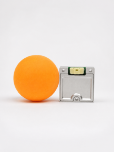
The Industrial High Precision IMU HM-G12 is a compact 6-axis inertia sensor integrating three-axis gyroscopes, three-axis accelerometers, and an MCU. It is presented for drones, robotics, and industrial motion-sensing applications. The supplied product information emphasizes low-noise inertial measurement, full-temperature calibration, high-rate output, compact dimensions, UART integration, and screw mounting.
The module provides 200 Hz gyroscope bandwidth and 200 Hz accelerometer bandwidth. Its product summary lists a 1000 Hz output rate, allowing data to be sent frequently to a host controller. Keep these characteristics separate during comparison: bandwidth concerns the physical measurement response, while output rate concerns digital data delivery. The product also lists full-temperature calibration across its -40°C to 85°C operating range.
| Category | Parameter | Specification |
|---|---|---|
| Gyroscope | Bandwidth | 200 Hz |
| Angular Random Walk | ≤ 0.15°/√h | |
| Bias Instability | ≤ 1.4°/h | |
| Bias Stability | ≤ 4°/h | |
| Orthogonality Error | ≤ 0.05° | |
| Accelerometer | Accelerometer Range | ±16g |
| Velocity Random Walk | 0.018 m/s/√h | |
| Bias Instability | 0.016 mg | |
| Bias Stability | 0.055 mg | |
| Bandwidth | 200 Hz | |
| Electrical Interface | External Data Interface | UART ×1 (Default) |
| Operating Current | ≤ 31 mA | |
| Input Voltage | DC 5 ± 0.5 V | |
| Interface Type | 10-pin connector, 3.3 V digital signal level | |
| Mechanical | Dimensions | 30 mm × 30 mm × 10.6 mm |
| Operating Temperature | -40°C to 85°C | |
| Weight | 14 g | |
| Storage Temperature | -40°C to 85°C |
HM-G12 product highlights
- ✅ High-precision 6-axis inertial sensing using three-axis gyroscopes and three-axis accelerometers.
- ✅ 1.4°/h gyro bias instability listed in the product summary.
- ✅ 0.016 mg accelerometer bias instability.
- ✅ ±16 g accelerometer measurement range.
- ✅ 200 Hz gyroscope and accelerometer bandwidth.
- ✅ 1000 Hz output rate listed in the product summary.
- ✅ Full-temperature calibration from -40°C to 85°C, according to the supplied product information.
- ✅ Built-in redundant architecture with sensor-status monitoring and fault detection, according to the supplied product information.
- ✅ Compact 30 mm × 30 mm × 10.6 mm dimensions.
- ✅ 14 g module weight.
- ✅ UART connectivity through a 10-pin connector.
- ✅ Screw mounting for stable mechanical integration.
The combination of compact construction, low listed bias values, industrial temperature coverage, and high-rate output makes the HM-G12 a reasonable candidate for robotics, drones, motion-control systems, and industrial machinery. Final suitability still has to be established through application-specific testing and current manufacturer documentation.
Pay particular attention to the unstated gyroscope range, communication protocol, mounting drawing, timing behavior, vibration environment, and external estimator requirements. Those details can determine whether the module is straightforward to integrate or becomes an expensive engineering distraction later in the program.
View Product Details & Pricing ➔
Inertia Sensor Selection Checklist
Performance requirements
- ⚙️ Define the required gyroscope range and maximum credible angular rate.
- ⚙️ Compare gyro bias instability, angular random walk, and bias stability.
- ⚙️ Confirm that the accelerometer range includes shock and transient margin.
- ⚙️ Review accelerometer bias instability, stability, and velocity random walk.
- ⚙️ Examine orthogonality, axis alignment, scale factor, and cross-axis performance.
- ⚙️ Separate physical bandwidth from digital output rate.
- ⚙️ Verify latency, timestamp precision, synchronization, and filter behavior.
- ⚙️ Determine what happens when a channel saturates or data packets are lost.
Environmental requirements
- ⚙️ Confirm operating and storage temperature limits.
- ⚙️ Define expected vibration, shock, and resonance exposure.
- ⚙️ Evaluate electromagnetic compatibility and nearby electrical-noise sources.
- ⚙️ Identify moisture, dust, altitude, and enclosure requirements.
- ⚙️ Review warm-up behavior and temperature-calibration coverage.
- ⚙️ Check whether mechanical stress from mounting can affect performance.
Integration requirements
- ⚙️ Confirm supply voltage, current consumption, and digital logic levels.
- ⚙️ Select the required UART, CAN, SPI, Ethernet, or other interface.
- ⚙️ Review connector, cabling, grounding, shielding, and strain-relief needs.
- ⚙️ Check dimensions, mass, mounting holes, and axis orientation.
- ⚙️ Obtain protocol documentation, configuration instructions, and firmware information.
- ⚙️ Verify startup timing, error handling, and power-cycle behavior.
Commercial and lifecycle factors
- ✅ Check engineering-sample availability and production lead time.
- ✅ Request calibration traceability and specification test conditions.
- ✅ Evaluate firmware stability and change-control practices.
- ✅ Confirm long-term supply, obsolescence notification, and customization options.
- ✅ Review technical support, validation, return, and warranty processes.
- ✅ Confirm that production units will be tested to the same requirements as evaluation units.
Compare candidate sensors with the same trajectory, vibration profile, temperature range, mounting arrangement, filter settings, and estimator configuration. A single headline value cannot represent system performance. The best inertia sensor is the one that satisfies the complete motion, environmental, electrical, integration, and lifecycle requirement at an acceptable total cost.
Look at total cost rather than unit price alone. A cheaper sensor can become expensive if it requires a custom isolation mount, extensive temperature compensation, repeated field calibration, or months of software work. A higher-performing module may reduce integration risk, but only if its specifications apply to the conditions your machine will actually experience.
Choose the Inertia Sensor That Matches the Motion Problem
An inertia sensor must be evaluated as part of the complete motion-estimation and control system. Gyro bias, angular random walk, accelerometer bias, bandwidth, temperature behavior, vibration response, mounting accuracy, latency, and interface compatibility all influence real-world results. Output rate alone is not a sufficient selection criterion, and an impressive bench specification does not remove the need for platform-level validation.
The HM-G12 provides a practical industrial option for systems requiring compact 6-axis sensing, 200 Hz gyroscope and accelerometer bandwidth, high-rate output, full-temperature calibration, a ±16 g accelerometer range, and UART integration. Its 30 mm × 30 mm × 10.6 mm enclosure and 14 g weight also provide concrete mechanical parameters for early system design.
Before approval, confirm the required gyroscope range, interface protocol, timing behavior, mounting orientation, environmental limits, and estimator compatibility. Test the production-intent installation under representative movement, vibration, temperature, power, and electrical-noise conditions. In the shop, that final installed test is where good specifications either prove themselves or fall apart.
Request product information or view the Industrial High Precision IMU HM-G12
Frequently Asked Questions
What is an inertial sensor used for in robotics?
An inertial sensor measures angular velocity and linear acceleration so a robot can estimate how its body is moving and changing orientation. In practice, this information supports attitude estimation, stabilization, motion control, dead reckoning, vibration monitoring, and sensor fusion. Gyro data tracks rapid rotation, while accelerometer data helps observe translational movement and the gravity vector.
These measurements are normally combined with wheel encoders, cameras, LiDAR, GNSS, joint sensors, or external positioning references because inertial error accumulates over time. In AGVs and AMRs, an inertia sensor can help estimate heading during wheel slip and bridge short gaps between localization updates. In UAVs, it is a core flight-control input. In robot arms, it can help characterize end-effector movement, vibration, and orientation. The HM-G12 combines three-axis gyroscopes and three-axis accelerometers in a compact 6-axis industrial IMU.
Where should I mount an inertia sensor, and what causes sensor errors?
Mount an inertia sensor rigidly to the structural reference whose movement you need to measure. Align the sensing axes with the robot, vehicle, payload, or flight-controller coordinate system, and document the installed orientation in software. For a mobile platform, placing the sensor near the body reference point or center of rotation can reduce lever-arm effects. A sensor installed on a robot end effector, however, may intentionally measure local movement rather than base movement.
Common error sources include vibration, mounting flex, axis misalignment, temperature drift, electrical noise, unstable power, poor calibration, packet-timing errors, and communication failures. Loose or overly soft mounting can introduce resonances and phase differences that software cannot reliably remove. Validate the installation with static tests, dynamic trajectories, temperature cycling, vibration testing, and communication checks. For the HM-G12, use its screw-mounting provisions and verify the 10-pin connector, DC 5 ± 0.5 V supply requirement, and 3.3 V digital signal level during integration.
How should I compare industrial IMUs within my budget?
Start with the real operating conditions instead of comparing purchase price and output rate alone. For gyro performance, review range, bias instability, angular random walk, bias stability, bandwidth, and orthogonality or cross-axis specifications. For the accelerometer, examine range, bias instability, bias stability, velocity random walk, bandwidth, and expected shock behavior. Then compare temperature calibration, vibration response, latency, timestamp quality, interface compatibility, dimensions, weight, current consumption, documentation, and technical support.
A lower-cost IMU may be adequate for short-duration stabilization but unsuitable for long dead-reckoning intervals or severe temperature changes. A highly precise sensor may be unnecessary when the system receives frequent external corrections. The HM-G12 provides a concrete comparison point with ≤ 1.4°/h gyro bias instability, 0.016 mg accelerometer bias instability, a 1000 Hz output rate listed in the product summary, UART connectivity, a ±16 g accelerometer range, and full-temperature calibration from -40°C to 85°C. Request current test conditions, interface documentation, sample data, and application support before approving it for production.
📚 References & Further Reading
- Product Information: Industrial High Precision IMU HM-G12






