


Obstacle Avoidance Drone Guide: Choosing LiDAR Sensing for Safer UAV Navigation
Here’s the deal: an obstacle avoidance drone is no longer just a premium feature for consumer quadcopters. In industrial UAV work, robotics labs, inspection programs, autonomous navigation projects, terrain-following systems, and field data collection, obstacle avoidance is becoming a basic engineering requirement. When a drone is flying near bridges, warehouses, trees, cranes, wind turbines, power lines, scaffolding, or indoor test rigs, one hard strike can cost more than the aircraft. Broken props are cheap. Damaged cameras, LiDAR payloads, RTK receivers, custom electronics, or one-off research boards can stop a whole project cold. For engineers and UAV developers, obstacle avoidance is not about convenience. It is about protecting payloads, improving mission reliability, and giving autonomous systems a fighting chance in messy real-world environments.
Look, every sensing method has tradeoffs. Many drones rely on cameras, ultrasonic sensors, GPS, visual positioning, or a mix of all of them. Cameras need texture and decent light. Ultrasonic sensors are usually short range and low resolution. GPS can tell a drone where it is, but it cannot see a wall, cable, tree branch, or forklift in the flight path. This is where compact dToF LiDAR sensing earns its place. A solid-state LiDAR module can deliver real-time distance data, depth images, and 3D point cloud information for near-field perception. In this guide, we will walk through how obstacle avoidance drones work, compare common sensing technologies, explain when LiDAR is the better choice, and show how a lightweight module such as the DTOF Solid State LiDAR HM-LD1 can support safer UAV navigation, prototyping, terrain following, and autonomous robotic development.
Table of Contents
- 👉 What Is an Obstacle Avoidance Drone?
- 👉 Why Obstacle Avoidance Matters for Industrial UAVs
- 👉 How Drone Obstacle Avoidance Works
- 👉 Obstacle Avoidance Sensor Technologies Compared
- 👉 Why LiDAR Is Valuable for Drone Obstacle Avoidance
- 👉 What Is dToF LiDAR and How Does It Work?
- 👉 DTOF Solid State LiDAR HM-LD1 for Obstacle Avoidance Drone Development
- 👉 Drone Integration Architecture: Sensor, Controller, and Software
- 👉 Industrial Use Cases for Obstacle Avoidance Drones
- 👉 How to Choose an Obstacle Avoidance LiDAR Module
- 👉 Deployment Best Practices and Engineering Tips
- 👉 Obstacle Avoidance Drone FAQ
What Is an Obstacle Avoidance Drone?
An obstacle avoidance drone is a UAV equipped with sensors and software that help it detect nearby objects and react before a collision happens. In a simple consumer drone, that may mean slowing down, stopping, or nudging around an object during manual flight. In a serious industrial system, obstacle avoidance becomes part of a larger autonomy stack that may include mapping, localization, waypoint navigation, terrain following, object tracking, inspection path planning, and emergency braking.
Sharing a compact dToF sensor we’ve been working with for drone obstacle av…
In the shop, we usually think about obstacle avoidance as a closed-loop safety process. The drone has to perceive the environment, decide whether an object is a real threat, and then command the aircraft to do something useful. That response might be as simple as blocking a forward stick command when a wall is too close. It might also be as complex as rerouting around a steel beam while holding a fixed inspection distance from a bridge face.
Three layers are usually involved. The first layer is perception, where sensors such as LiDAR, stereo cameras, ultrasonic sensors, radar, optical flow cameras, or depth cameras detect objects. The second layer is decision-making, where software evaluates distance, direction, velocity, and risk. The third layer is control response, where the drone brakes, hovers, reroutes, climbs, descends, or maintains a safe standoff distance.
Consumer Obstacle Avoidance vs Industrial Obstacle Avoidance
Consumer obstacle avoidance systems are usually tuned for photography, casual flight safety, and protecting a camera drone from obvious mistakes. They help users avoid trees, walls, people, and large objects while capturing video. Industrial drone obstacle avoidance has a tougher job. It needs predictable output, real-time range data, compatibility with external flight controllers, embedded software integration, and documented operating limits. Engineers need to know the sensor field of view, frame rate, range, weight, interface, power consumption, and operating temperature before they can design it into a vehicle with confidence.
Industrial UAV developers also care about repeatability. A research drone flying through a warehouse test course should detect the same obstacle in roughly the same position across repeated trials. An inspection drone operating near a dam, bridge, or expressway needs distance measurements that support conservative safety rules. For teams building visual-inertial or SLAM-based autonomy, our guide on how to build VIO and VSLAM systems explains how perception and localization technologies can work together inside a broader navigation stack.
Why Obstacle Avoidance Is Not the Same as Autonomous Navigation
Obstacle avoidance is a safety layer. Autonomous navigation is the broader capability to move from one location to another using positioning, mapping, perception, and motion control. A drone can have obstacle avoidance without full autonomy, and it can have autonomous waypoint navigation without reliable near-field obstacle detection. The safest UAV systems combine both. GPS or RTK can help define where the drone should go, while LiDAR or depth sensing can help determine whether the immediate flight corridor is actually safe.
Why Obstacle Avoidance Matters for Industrial UAVs
Industrial drones often operate in places where manual flying is difficult and GPS alone is not enough. Think bridge inspections, warehouse flights, under-canopy mapping, dam inspection, construction monitoring, power infrastructure inspection, tunnel research, mine research, agriculture, and robotics education. These environments contain irregular obstacles such as beams, cables, walls, columns, trees, terrain changes, scaffolding, machinery, temporary work platforms, and moving vehicles.
Obstacle avoidance matters because it reduces collision risk, protects expensive payloads, increases confidence in semi-autonomous operation, enables repeatable missions, improves safety around people and assets, and supports research or product development. It also helps close the gap between laboratory autonomy and field deployment. A prototype drone may behave nicely in open air, but the real engineering challenge starts when the aircraft has to operate near complex structures that were not designed with drones in mind.
The Cost of a Drone Collision
A collision may damage the UAV frame, propulsion system, propellers, gimbal, camera payload, LiDAR mapping payload, RTK receiver, companion computer, battery, wiring harness, or test electronics. For industrial teams, downtime can be more expensive than the broken parts. A crash during an inspection program can delay data collection, create safety concerns, and force a revalidation of the airframe. A crash during an R&D project can destroy prototype electronics that may take weeks to rebuild or replace.
GPS Alone Cannot See Obstacles
GPS or RTK positioning can tell a drone where it is, but it cannot tell whether a tree branch, wall, vehicle, crane cable, hanging sign, or bridge beam is in the flight path. Positioning and obstacle perception solve different problems. For high-precision outdoor positioning, read our guide to the HM-D20 RTK module. For safer autonomous navigation, RTK positioning should often be combined with near-field perception such as LiDAR or depth sensing.
This distinction matters in the real world. A drone may follow a waypoint route with centimeter-level positioning accuracy and still hit a temporary obstacle that was not included in the mission plan. A parked vehicle, newly installed scaffold, moving worker, hanging cable, or overgrown branch can defeat a route that looks safe on a map. Obstacle avoidance gives the drone a local awareness layer that complements global positioning.
How Drone Obstacle Avoidance Works
A drone obstacle avoidance system follows a continuous loop. The sensor captures distance or image data. The onboard processor interprets the environment. The control software determines whether an obstacle is close enough to require action. The flight controller receives commands to slow, stop, reroute, or maintain a safe distance. This process has to happen repeatedly and reliably while the aircraft is moving, vibrating, tilting, and responding to wind or pilot input.
Step 1: Sensing the Environment
Obstacle avoidance starts with sensing. Sensors may generate single-point range data, multi-zone distance data, a depth map, a 3D point cloud, optical flow, a stereo disparity map, or radar returns. LiDAR-based systems are especially useful when direct distance measurement is required. Instead of estimating distance only from visual patterns, LiDAR measures distance using emitted light and reflected signals.
Step 2: Estimating Distance and Direction
For obstacle avoidance, distance alone is not enough. The system must understand how far the obstacle is, where it appears in the field of view, whether the UAV is moving toward it, whether it lies inside the planned flight corridor, and how quickly the situation is changing. A forward-facing sensor may detect objects in the center, left, or right side of the field of view. The software can then decide whether to slow down, turn away, hold position, or ignore an object that is outside the danger zone.
Step 3: Defining a Safety Zone
Developers typically define safety zones such as warning distance, braking distance, emergency stop distance, a no-fly bubble around the UAV, a terrain-following height band, or a landing clearance zone. These zones should not be guessed. They should be based on aircraft speed, mass, braking behavior, frame rate, processing latency, environmental risk, and the consequences of collision. A slow indoor research drone can use shorter thresholds than a faster outdoor inspection UAV.
Step 4: Flight Controller Response
When an obstacle enters a defined zone, the software may command the drone to brake and hover, climb above the obstacle, descend below the obstacle, move laterally, reduce speed, trigger return-to-home, reject pilot input in an unsafe direction, or update an autonomous trajectory. In many systems, obstacle avoidance begins with conservative speed reduction instead of aggressive evasive maneuvers. That is usually the smarter move because sudden avoidance commands can destabilize the vehicle or create a new collision risk.
Step 5: Sensor Fusion
Advanced obstacle avoidance drones often combine LiDAR with IMU, GPS, RTK, barometer, optical flow, or visual SLAM. Sensor fusion helps compensate for the limitations of any single technology. For example, an IMU provides short-term motion information, RTK provides outdoor position, a barometer estimates altitude, a camera provides visual context, and LiDAR provides direct distance measurement. When the design is done properly, the combined system is more robust than one sensor operating alone.
Obstacle Avoidance Sensor Technologies Compared
Different obstacle avoidance sensors have different strengths. The right choice depends on operating range, payload limit, lighting, target material, speed, integration complexity, and budget. Leading LiDAR companies such as Hesai Technology and industrial sensor manufacturers such as SICK show how important reliable distance sensing has become across robotics, vehicles, automation, and industrial safety systems.
LiDAR
LiDAR measures distance using light. Depending on the module, it can provide accurate range information, depth maps, or point clouds. Solid-state LiDAR is especially attractive for drones because it avoids bulky rotating mechanisms and can be compact enough for weight-sensitive UAV platforms. For a LiDAR obstacle avoidance drone, the value is direct distance measurement in a format that software can convert into safety zones.
Stereo Cameras
Stereo cameras estimate depth by comparing two images. They are useful in textured, well-lit environments and can support visual navigation, SLAM, and object recognition. The catch is that stereo vision may struggle with low-texture walls, poor lighting, glare, fog, motion blur, transparent surfaces, and repetitive patterns. It also requires processing resources and stable calibration.
Ultrasonic Sensors
Ultrasonic sensors are low-cost and simple, but they usually have short range, wide beam angles, low spatial resolution, and sensitivity to surface angle or environmental noise. They can be useful for landing assist or basic indoor proximity detection, but they are often not enough as the primary sensing technology for industrial drone obstacle avoidance.
Radar
Radar can work in dust, fog, smoke, and poor visibility. It can also measure relative motion effectively. However, compact drone radar modules may have lower spatial resolution than LiDAR or vision-based depth sensors. Radar can be useful in harsh environments, but the software design must account for the type of data it produces.
Optical Flow Sensors
Optical flow helps estimate motion relative to the ground, especially for indoor stabilization and low-altitude hover. However, optical flow is not a full obstacle avoidance solution by itself. It does not provide complete forward obstacle detection and depends on visual texture and lighting.
| Sensor Type | Strengths | Limitations | Best Drone Use Cases |
|---|---|---|---|
| LiDAR / dToF LiDAR | Direct distance measurement, depth data, works in many lighting conditions, strong for near-field perception | Range can vary by reflectivity and sunlight; integration requires processing logic | Obstacle avoidance, terrain following, inspection, robotics research |
| Stereo Camera | Rich visual data, useful for mapping and object recognition | Depends on lighting and texture; depth accuracy varies with distance | Visual navigation, SLAM, object recognition |
| Ultrasonic | Low cost, simple integration, useful at short range | Short range, low resolution, affected by angle and soft materials | Landing assist, basic indoor avoidance |
| Radar | Robust in dust, fog, smoke, and poor visibility | Lower spatial detail in compact systems | Harsh environments, speed measurement, all-weather detection |
| Optical Flow | Useful for position hold and motion estimation | Not sufficient for full obstacle detection | Indoor stabilization, low-altitude hover |
Why LiDAR Is Valuable for Drone Obstacle Avoidance
LiDAR is valuable because it provides direct distance measurement. Instead of inferring distance only from image patterns, LiDAR measures the time or behavior of emitted light as it returns from objects. For an obstacle avoidance drone, this is a major advantage because the control system needs distance data quickly and repeatedly. If readers need a foundational explanation, see our guide on what LiDAR stands for and how LiDAR works.
Direct Distance Data for Real-Time Decisions
Obstacle avoidance requires fast distance updates. A drone moving forward must know whether an object is within braking distance. LiDAR can provide a depth map or range data that software can convert into warning zones. This makes it well suited for behaviors such as slow-down thresholds, emergency hover commands, landing clearance checks, and terrain distance monitoring.
Useful for Low-Texture Obstacles
Walls, floors, ceilings, pipes, bridge surfaces, dams, and infrastructure components may not provide enough visual texture for stereo depth. LiDAR can often detect distance even when visual texture is limited. That does not mean LiDAR is perfect in every condition, but it is a strong complement to camera-based perception in structured industrial environments.
Compact Solid-State Designs for UAV Payload Limits
Traditional scanning LiDAR can be heavy, costly, or power-hungry. Solid-state dToF modules are more suitable for compact UAVs because they can be lightweight, low power, and easier to mount. On drones, every gram affects flight time and payload margin. A compact sensor makes it easier to add obstacle detection without redesigning the entire aircraft.
Depth Maps and Point Clouds for More Than Collision Avoidance
A LiDAR module that outputs depth maps or point cloud data can support obstacle detection, zone monitoring, terrain following, altitude hold, landing assist, SLAM research, object distance measurement, volume measurement, and smart inspection. That is useful for developers because one sensor can support multiple functions as a UAV project matures.
What Is dToF LiDAR and How Does It Work?
dToF stands for direct Time of Flight. A dToF LiDAR emits light pulses and measures the time it takes for reflected photons to return to the sensor. Because light travels at a known speed, the system can calculate distance from the measured travel time. This principle is powerful for compact drone sensing because it directly links the measured return signal to object distance.
Direct Time of Flight Principle
In a direct Time of Flight system, an emitter sends a light pulse into the environment. The light reflects from an object, and the receiver detects the returning photons. The system calculates the time delay between emission and reception, then converts that delay into distance. In a multi-pixel or depth-sensing module, this process is performed across a sensing array to create a depth image or spatial distance field.
Why SPAD Sensors Matter
SPAD stands for Single-Photon Avalanche Diode. SPAD-based sensing is highly sensitive and can detect very small amounts of returned light. This sensitivity is useful in compact LiDAR systems where power, size, and thermal limits matter. For UAVs, SPAD dToF technology can help achieve practical depth sensing in a compact module that can be mounted on a drone, robot, or embedded platform.
Depth Image vs Point Cloud
A depth image represents distance values across a two-dimensional sensor grid. A point cloud converts distance data into three-dimensional spatial points. For UAVs, a depth image may be enough for obstacle zone detection, while point cloud data can be useful for mapping, SLAM, inspection, and spatial analysis. The choice depends on the autonomy goal, processor capability, and required control response.
Important Performance Factors
When selecting a dToF LiDAR drone sensor, engineers should evaluate range, accuracy, field of view, resolution, frame rate, outdoor light tolerance, weight, power consumption, interface compatibility, SDK support, and temperature range. These specifications determine whether the sensor is suitable for a specific drone mission. For example, a sensor with a wide field of view may help detect more of the flight corridor, while a lightweight sensor improves payload flexibility.
DTOF Solid State LiDAR HM-LD1 for Obstacle Avoidance Drone Development
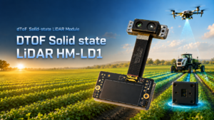
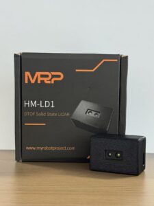
The DTOF Solid State LiDAR HM-LD1 is a compact SPAD dToF LiDAR module designed for real-time depth sensing, point cloud output, obstacle avoidance, distance detection, autonomous navigation, robotic vision, and smart inspection applications. Its compact size, 28 g weight, 1.2 W power consumption, and multiple interfaces make it suitable for UAV prototypes, robotic platforms, Raspberry Pi projects, embedded systems, and companion-computer-based autonomy development.
For obstacle avoidance drone development, the HM-LD1 is especially relevant because it provides real-time depth images and 3D point cloud data in a compact solid-state design. It supports indoor or nighttime ranging up to 25 m and outdoor daytime ranging up to 8 m, giving developers a practical near-field sensing option for controlled UAV navigation, altitude hold, terrain following, and collision risk reduction.
Download DTOF SSL HM-LD1 Product Brochure

| DTOF Solid State LiDAR HM-LD1 Specifications | |
|---|---|
| Product Name | DTOF Solid State LiDAR HM-LD1 |
| Technology | SPAD dToF solid-state LiDAR |
| Dimension | 43.5 mm × 30 mm × 26.5 mm |
| Ranging Capability | Indoor: 0.5–25 m; Outdoor: 0.2–8 m |
| Ranging Accuracy | ±3 cm |
| Field of View | 60° horizontal × 45° vertical |
| Weight | 28 g |
| Resolution | 40 × 30 |
| Frame Rate | 10 fps |
| Interface | UART / UDP / UVC |
| Operating Temperature | -20 ℃ to 60 ℃ |
| Power Consumption | 1.2 W |
| Supported Development Platforms | SDKs for x86 Windows, x86 Linux, and ARM Linux |
| Typical Applications | UAV obstacle avoidance, altitude hold, terrain following, robotic navigation, SLAM, distance detection, smart inspection, zone intrusion monitoring |
View Product Details & Pricing ➔
Why These Specs Matter for UAV Designers
The HM-LD1 weighs 28 g, and that matters because drone payload weight directly affects flight time, maneuverability, and battery margin. A lightweight obstacle avoidance sensor is easier to add to an existing UAV platform without forcing a major airframe redesign. Its 1.2 W power consumption also makes it easier to support from onboard power systems, especially in compact drones where every watt contributes to thermal load and battery drain.
The 60° horizontal by 45° vertical field of view is useful for directional sensing. Mounted forward-facing, it can monitor a practical section of the flight path. Mounted downward-facing, it can support altitude measurement and terrain following. The 40 × 30 resolution provides multi-zone spatial information rather than a single distance value, allowing software to evaluate whether the center flight corridor is blocked or whether an obstacle is off to one side.
The 10 fps frame rate provides repeated distance updates for controlled flight speeds and prototype autonomy. Developers still need to match flight speed to detection range and braking distance, but a repeated depth stream is far more useful than occasional manual distance readings. The UART, UDP, and UVC interfaces allow integration with embedded controllers, companion computers, PCs, and vision pipelines. SDK support for x86 Windows, x86 Linux, and ARM Linux makes the module practical for both laboratory development and embedded deployment.
Need a Compact LiDAR Module for an Obstacle Avoidance Drone?
The DTOF Solid State LiDAR HM-LD1 provides real-time depth images and 3D point cloud data in a lightweight 28 g module with UART, UDP, and UVC interfaces.
Drone Integration Architecture: Sensor, Controller, and Software
An obstacle avoidance drone system usually includes the LiDAR sensor, flight controller, companion computer, power system, and software logic. The LiDAR module detects distance. A companion computer or embedded controller processes the sensor output. The flight controller receives control commands or safety triggers. The engineering challenge is making these components communicate reliably under real flight conditions, not just on a bench with clean power and no vibration.
Companion Computer Options
The HM-LD1 supports integration with development platforms such as PCs, Raspberry Pi systems, embedded Linux computers, ARM Linux systems, x86 Windows systems, and x86 Linux systems. This is useful because UAV development often starts on a PC for visualization and logging, then moves to a smaller companion computer for flight testing. Developers can build algorithms in stages, validate sensor data first, and only then connect the output to flight control behavior.
Interface Selection
UART is useful for embedded control and simpler distance data integration. UDP is useful for networked systems and higher-level computing platforms. UVC can be convenient for video or depth streaming workflows and PC-based prototyping. The correct interface depends on how the system is architected, what processor is available, and whether the project prioritizes low-level control, rapid visualization, or integration with existing vision pipelines.
Mounting Positions on a Drone
A LiDAR module may be mounted forward-facing for collision avoidance, downward-facing for altitude hold and terrain following, rear-facing for reverse movement safety, side-facing for wall following, or in a multi-sensor arrangement for wider coverage. The sensor should have a clear field of view, secure mounting, clean optical access, and minimal interference from landing gear, propellers, payload brackets, or cables.
Software Logic Considerations
Software logic should be conservative and easy to validate. A basic system can define a slow-down threshold and an emergency hover threshold. More advanced systems can divide the depth image into regions, evaluate whether the center flight corridor is blocked, and command a safer trajectory. Developers should check data format, timestamping, latency, calibration, coordinate frame alignment, SDK availability, CPU load, power budget, and vibration isolation before relying on the sensor for autonomous response.
Industrial Use Cases for Obstacle Avoidance Drones
Bridge, Expressway, and Dam Inspection
Infrastructure inspection often requires drones to fly near hard surfaces, beams, columns, rails, or vertical faces. The HM-LD1 product details specifically mention objects that are difficult for people to approach, such as bridges, expressways, and dams. For UAV inspection, near-field sensing helps maintain safe distances from infrastructure while reducing the risk of collision with protrusions, edges, corners, and irregular surfaces.
Indoor Warehouses and Industrial Facilities
Indoor UAVs may operate around shelves, columns, walls, machinery, ceilings, hanging signs, pipes, and moving equipment. GPS may be unavailable indoors, which increases the value of onboard perception. A compact dToF LiDAR can support forward obstacle detection, wall distance measurement, and controlled indoor experimentation when combined with a suitable flight controller and localization method.
Terrain Following and Altitude Hold
A downward-facing dToF LiDAR can support altitude measurement and terrain following where barometric altitude or GPS height is not precise enough. This is useful for low-altitude inspection, agriculture, robotics research, and controlled flight near uneven surfaces. The software must account for field of view, surface reflectivity, aircraft attitude, and flight speed.
Robotics Education and Student Drone Projects
A practical student project can use a compact LiDAR module, Raspberry Pi or companion computer, flight controller, and SDK-supported development environment. The first goal should be simple and safe: detect an object in front of the drone, slow down, and hover before collision. From there, students can expand into depth maps, point clouds, region-based obstacle detection, or sensor fusion.
SLAM and Autonomous Navigation Research
Depth data and point cloud output can support research into mapping, localization, and navigation. LiDAR data can help build local obstacle maps, evaluate clear space, and support experimental autonomy stacks. For teams combining LiDAR with cameras and inertial sensors, the earlier linked VIO and VSLAM guide provides additional context on visual localization systems.
Security, Zone Monitoring, and Intrusion Detection
LiDAR depth sensing can also be used beyond flight control. It can support static zone monitoring, object presence detection, smart inspection, and security applications. A module capable of depth images and point cloud data can detect whether objects enter a defined region, estimate object distance, or assist in volume measurement workflows.
How to Choose an Obstacle Avoidance LiDAR Module
Choosing a LiDAR module for a drone requires balancing performance, size, weight, power, integration, and environmental needs. A sensor that performs well on a ground robot may be too heavy for a drone. A sensor that works indoors may have reduced outdoor range in bright sunlight. A sensor with good range may still be hard to use if the interface or SDK does not match the development platform.
✅ 1. Ranging Distance
The sensor must detect obstacles early enough for the aircraft to slow or stop. Outdoor sunlight can reduce range, so buyers should compare indoor and outdoor performance separately. The HM-LD1 specifies indoor ranging capability of 0.5 to 25 m and outdoor ranging capability of 0.2 to 8 m.
✅ 2. Accuracy
Accuracy determines how confidently the UAV can maintain distance from obstacles. The HM-LD1 offers ±3 cm ranging accuracy, which is useful for near-field distance measurement, controlled standoff behavior, and prototype obstacle avoidance logic.
✅ 3. Field of View
A wider field of view covers more of the flight path. HM-LD1 provides a 60° horizontal by 45° vertical field of view. This is practical for directional sensing, but developers should remember that a single module does not provide full 360-degree coverage.
✅ 4. Resolution
Resolution affects how much spatial detail the sensor provides. A 40 × 30 depth resolution gives multi-zone distance data rather than a single-point measurement. This allows algorithms to evaluate different regions of the sensor view and make more informed safety decisions.
✅ 5. Frame Rate
Frame rate affects how often the UAV receives updated distance information. The required frame rate depends on flight speed, braking distance, and control loop design. The HM-LD1 provides 10 fps, which can support controlled-speed prototype autonomy and near-field safety logic when thresholds are designed conservatively.
✅ 6. Weight and Power
Every gram matters on a drone. At 28 g and 1.2 W, HM-LD1 is suitable for weight-sensitive platforms. These specifications are important not only for flight time but also for thermal management, wiring, voltage regulation, and total payload budget.
✅ 7. Interface and SDK
Check whether the module supports the development environment. HM-LD1 supports UART, UDP, UVC, and SDKs for x86 Windows, x86 Linux, and ARM Linux. This flexibility makes it easier to prototype on a PC and later migrate to an embedded platform.
✅ 8. Environmental Suitability
Consider operating temperature, sunlight tolerance, reflectivity, dust, vibration, and mounting protection. HM-LD1 is specified for an operating temperature range of -20 ℃ to 60 ℃. Outdoor performance should still be validated with real target materials, sunlight angles, and mission speeds.
Deployment Best Practices and Engineering Tips
⚙️ Calibrate Sensor Orientation
The LiDAR coordinate frame must align with the drone body frame. Even small angular mounting errors can affect obstacle position estimation. If the sensor is tilted down, up, or sideways, the software should account for that angle when interpreting depth data. Calibration should be documented so mechanical changes do not quietly invalidate the obstacle avoidance behavior.
⚙️ Use Conservative Safety Thresholds
Obstacle avoidance should include safety margins for latency, braking distance, wind, velocity, and control response. Do not use the maximum sensor range as the only safety threshold. A better approach is to define multiple zones, such as warning, slow-down, and emergency hover. This makes the UAV behavior smoother and easier to test.
⚙️ Test Indoors Before Outdoor Flights
Start in a controlled environment. Validate sensor output, distance thresholds, mounting vibration, and software response before outdoor testing. Indoor testing allows developers to use repeatable obstacle distances, known target materials, and safer low-speed flight. Once the system is stable, outdoor testing can introduce sunlight, wind, reflective surfaces, and more complex backgrounds.
⚙️ Consider Sunlight and Target Reflectivity
Outdoor range may vary depending on sunlight, target material, reflectivity, and angle. HM-LD1 specifies outdoor ranging capability of 0.2 to 8 m. Developers should test concrete, vegetation, painted metal, dark objects, bright objects, and angled surfaces. A robust system should be tuned based on real mission conditions rather than ideal laboratory assumptions.
⚙️ Avoid Blind Trust in One Sensor
For higher-reliability autonomy, combine LiDAR with other sensors such as IMU, GPS/RTK, barometer, optical flow, or cameras. No single sensor detects every object perfectly. Thin wires, transparent materials, highly reflective surfaces, vibration, dirt, and environmental interference can all create edge cases. Sensor fusion and conservative flight rules reduce the likelihood that one failure mode leads to a crash.
⚙️ Match Flight Speed to Detection Range
A drone moving too quickly may not stop within the detected distance. The safety algorithm must account for speed, latency, frame rate, and braking behavior. If outdoor sensing range is 8 m, the drone should not fly so fast near structures that it cannot slow or stop inside that distance. Speed limiting is one of the simplest and most effective ways to improve obstacle avoidance reliability.
⚙️ Protect the Sensor from Vibration and Dirt
Mount the module securely and keep the optical window clean. UAV vibration and dust can affect sensor stability and data quality. Cables should be strain-relieved, the mounting bracket should be rigid, and the sensor should be protected from impacts without blocking its field of view. Maintenance checks should include optical inspection and verification of live depth output.
Build Safer UAV Navigation with dToF LiDAR
Explore compact LiDAR sensing for UAV obstacle avoidance, terrain following, robotic vision, and autonomous navigation development.
Obstacle Avoidance Drone FAQ
Is drone obstacle avoidance really worth the extra cost?
What is a low-cost obstacle avoidance setup for a student or DIY drone project?
Can an obstacle avoidance drone also support GPS, tracking, or autonomous navigation?
What is the best sensor for drone obstacle avoidance?
Can LiDAR work outdoors on a drone?
How much range does an obstacle avoidance drone need?
Is LiDAR better than ultrasonic sensing for drones?
Where should a LiDAR sensor be mounted on a drone?
Can a single LiDAR module provide full 360-degree drone obstacle avoidance?
What data does a LiDAR module provide for drone navigation?
Does obstacle avoidance replace pilot skill?
📚 References & Further Reading
- Industry Standard: Hesai Technology and SICK for LiDAR and industrial sensing context.
- Related Guide: Build VIO and VSLAM Systems, HM-D20 RTK Module, and What Does LiDAR Stand For?






