

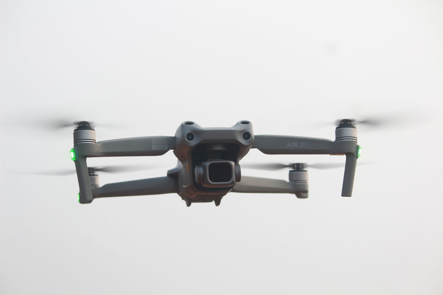
Drones with Collision Avoidance: How to Choose Reliable LiDAR-Based Obstacle Detection for UAV Projects
Here’s the deal: industrial UAV teams are past the old question of whether a drone can fly by itself. The real question is whether it can fly safely around cranes, bridge beams, warehouse racks, tree lines, power structures, mining walls, people, vehicles, and rough terrain without turning an expensive payload into scrap. In inspection, mapping, warehouse automation, agriculture, public safety, and robotics R&D, one collision can wreck the aircraft, damage a sensor package, stop the job, or create a safety problem nobody wants to explain later. That is why drones with collision avoidance are no longer just a premium feature. For serious work, they are part of the basic system design.
Look, not all obstacle detection systems behave the same way. Camera-only systems, ultrasonic sensors, radar, stereo vision, optical flow, and LiDAR each have strengths and weak spots. Some struggle in bright outdoor light. Some struggle in dust. Some need texture. Some work only at short range. Some are hard to integrate on a small airframe. For a UAV engineering team, the important question is not “Which sensor sounds best in a brochure?” It is “Which sensing method gives us dependable distance data under the actual conditions where this aircraft will fly?”
This guide walks through how to evaluate LiDAR-based collision avoidance for UAV projects from an engineering point of view: sensing range, field of view, frame rate, weight, interface, environmental robustness, integration path, and flight-controller compatibility. We will focus especially on compact solid-state dToF LiDAR modules because they provide direct distance measurement, real-time depth output, and lightweight integration for drones where every gram matters.
As a practical reference, we will look at the DTOF Solid-State LiDAR HM-LD1, a 28 g SPAD dToF module with 60° × 45° FOV, 40 × 30 resolution, UART/UDP/UVC interfaces, and indoor/outdoor ranging capability. It is suitable for UAV obstacle avoidance, terrain following, altitude hold, robotic navigation, embedded vision development, and smart inspection systems where close-range perception matters.
Table of Contents
- 👉 Why Collision Avoidance Matters for Industrial Drones
- 👉 What Collision Avoidance Means in UAV Systems
- 👉 Sensor Technologies Used in Drones with Collision Avoidance
- 👉 Why LiDAR Is a Strong Choice for UAV Obstacle Detection
- 👉 How dToF Solid-State LiDAR Works
- 👉 How to Choose a LiDAR Module for Drone Collision Avoidance
- 👉 UAV Integration Architecture: Sensor, Processor, and Flight Controller
- 👉 Industrial Applications for LiDAR-Based Collision Avoidance
- 👉 Product Reference: DTOF Solid-State LiDAR HM-LD1
- 👉 Engineering Checklist Before Deployment
- 👉 Common Mistakes When Building Drones with Collision Avoidance
- 👉 FAQ: Drones with Collision Avoidance
Why Collision Avoidance Matters for Industrial Drones
Industrial airspace is rarely clean, empty, or predictable. A consumer drone flying in an open park is one thing. A UAV working under a bridge, inside a warehouse aisle, around a communications tower, beside a dam wall, near a quarry face, or below a forest canopy is a different animal entirely. In those places, collision avoidance is not a convenience feature. It is an engineering control that helps protect the aircraft, payload, people, infrastructure, and the mission itself.
Collision risk is higher in real industrial airspace
In the shop and out in the field, the clean test environment disappears fast. Inspection drones often fly close to facades, tanks, power structures, bridges, turbines, pipes, roofs, cranes, scaffolding, and structural steel. Mining drones may work near rock walls, conveyors, benches, haul roads, machines, dust clouds, and uneven terrain. Warehouse drones deal with racks, beams, ceilings, forklifts, people, pallets, cables, and narrow aisles. Agriculture and forestry drones may run into tree canopies, poles, nets, irrigation hardware, fences, wires, and uneven ground.
When engineers build drones with collision avoidance, they have to assume the aircraft may approach objects from odd angles and under changing light. The obstacle may be big and obvious, such as a concrete wall, or hard to detect, such as a dark pipe, angled metal panel, glass surface, thin branch, or wire. A reliable drone anti-collision system has to be evaluated as a full perception and control chain, not as one shiny component mounted on the nose.
Payload protection and mission continuity
Industrial drones often carry payloads that cost more than the airframe. That might include thermal cameras, mapping sensors, multispectral cameras, gas detectors, robotic sampling tools, RTK GNSS receivers, or custom inspection instruments. A collision can destroy hardware, corrupt data, force emergency repairs, delay the project, and shake customer confidence. For companies running commercial UAV operations, downtime is not theoretical. It hits the schedule and the invoice.
Collision avoidance also protects data quality. If a drone needs to fly at a consistent standoff distance from a wall, pipe, bridge deck, tank, or warehouse rack, depth perception helps maintain that distance and reduces the amount of constant manual correction required from the pilot. For positioning accuracy beyond basic GNSS, see our guide to drone RTK and centimeter-level flight precision. RTK helps the drone understand where it is in global coordinates. LiDAR-based perception helps it understand what is immediately around it.
Autonomy depends on perception
Flight control keeps the drone stable. Perception helps the drone avoid doing something dumb while it is stable. A flight controller can maintain attitude, altitude, and position using IMU, barometer, GNSS, compass, optical flow, and other inputs. But a perfectly stabilized drone can still fly straight into a wall, shelf, tree, crane, bridge beam, or person if it has no local depth awareness.
That is why autonomous drone navigation needs perception sensors that can observe the nearby environment and feed actionable data into a planning or failsafe system. For industrial autonomy, this matters even more because the drone is often close to objects by design. The mission may require close inspection imagery, thermal scans, or measurement passes near infrastructure. Collision avoidance should be treated as part of the mission architecture, alongside navigation, localization, communications, safety procedures, and operator training.
What Collision Avoidance Means in UAV Systems
Collision avoidance gets marketed like a checkbox, but in engineering terms it is a system function. It requires sensing, processing, decision-making, and flight control. A LiDAR module may provide depth data, but that data has to be filtered, interpreted, and turned into a safe aircraft behavior before it becomes useful.
Obstacle detection vs. obstacle avoidance
Obstacle detection means the system senses that an object exists within a defined range or field of view. For example, a forward-facing LiDAR module may report that an object is 3 m ahead of the drone. Obstacle avoidance means the aircraft takes action based on that detection. It may slow down, stop, climb, descend, reroute, hold position, trigger a failsafe, or alert the pilot.
This distinction matters. A lot of teams install a sensor and assume the drone is now protected. It is not that simple. The sensor output must be connected to behavior. The most dependable drones with collision avoidance combine reliable sensing, conservative logic, and response rules that match the mission.
Reactive avoidance vs. predictive avoidance
Reactive avoidance responds to immediate threats. If an obstacle appears inside a minimum safety distance, the drone slows, stops, or holds position. Predictive avoidance goes further by estimating future motion, building a local map, planning a safer path, or using SLAM and trajectory planning to avoid conflicts before they become urgent.
Reactive systems are simpler and can work well for low-speed inspection, indoor tests, and basic anti-collision functions. Predictive systems are more complex and usually require sensor fusion, onboard computing, localization, and navigation software. Either way, the sensor must provide usable data early enough for the aircraft to respond safely.
Front, rear, side, upward, and downward sensing
A single forward-facing sensor can support forward obstacle detection, but it cannot see behind the drone, above it, or to the sides. Downward LiDAR can support altitude hold, landing assistance, and terrain following. Side-facing modules are useful in warehouse aisles, tunnels, corridors, or bridge inspections. Upward sensing matters when flying under beams, ceilings, canopies, pipes, or bridge decks.
Full omnidirectional obstacle avoidance usually requires multiple sensors or a broader perception architecture. The right sensing layout depends on how the drone moves. If the mission involves slow forward inspection, one forward module may be enough for a basic stop-or-slow function. If the drone flies sideways or backward near structures, blind zones become a serious risk.
Collision avoidance depends on speed
A sensor that works fine at low speed may be inadequate for faster flight. Safe detection distance depends on UAV velocity, processing delay, braking capability, and safety margin. Higher speeds require longer detection range because the drone covers more distance before it can react. Engineers need to consider sensor frame rate, data transmission latency, onboard processing time, flight-controller response, motor dynamics, and environmental uncertainty.
A slow inspection drone moving carefully near a wall can use shorter-range sensing effectively. A faster outdoor UAV needs earlier detection and more conservative thresholds. That is why collision avoidance validation must be done under realistic flight speeds and mission conditions, not just on a bench with a cardboard box in front of the sensor.
Sensor Technologies Used in Drones with Collision Avoidance
There is no universal sensor that solves every drone collision avoidance problem. Camera-based vision, ultrasonic sensing, millimeter-wave radar, LiDAR, optical flow, GNSS, IMU, and barometric sensing all bring something different to the table. Industrial UAV designs often use sensor fusion because one technology can cover another technology’s weak spot.
Camera-based vision
Cameras provide rich visual information and are widely used for inspection, mapping, AI object recognition, visual odometry, and operator awareness. Monocular cameras can identify objects, but they do not directly measure distance unless depth is inferred from motion, known geometry, or machine learning. Stereo cameras estimate depth by comparing two images, and optical flow can estimate motion relative to visual texture.
The limitations are familiar to anyone who has tested vision systems outside a clean lab: lighting, texture, shadows, glare, motion blur, repetitive patterns, and compute demand. A white warehouse wall, dark tunnel, reflective metal panel, or low-light industrial space can make camera-only collision avoidance unreliable. Cameras are powerful, but for distance-critical safety functions, direct ranging sensors are often a better foundation.
Ultrasonic sensors
Ultrasonic sensors are common in simple robotics and low-altitude ranging because they are inexpensive and easy to use. They emit sound and measure the echo return time. In drones, ultrasonic sensors can assist with short-range altitude hold or simple obstacle detection.
But ultrasonic sensing has hard limits. Range is usually short. The sensing cone may be narrow or irregular. Angled surfaces can reflect sound away from the receiver. Soft materials may absorb the signal. Acoustic noise can interfere. For industrial drones, ultrasonic sensors can be useful in narrow roles, but they are rarely enough for robust multi-scenario collision avoidance.
Millimeter-wave radar
Millimeter-wave radar is useful because it can perform well in dust, fog, rain, and poor visibility. It can detect objects when optical sensors struggle. Radar is especially valuable for presence detection, velocity estimation, and adverse-weather operation.
The tradeoff is spatial resolution. Radar may not provide the fine geometry that LiDAR or vision can deliver, especially for small objects or complex indoor scenes. For drones that need to maintain precise distance from infrastructure, radar is often paired with LiDAR or cameras to improve both robustness and scene detail.
LiDAR sensors
LiDAR measures distance using light. Depending on the design, a LiDAR sensor may output a single distance, a line scan, a depth image, or a 3D point cloud. For UAV obstacle detection, LiDAR is attractive because it provides direct range measurements that can be converted into safety thresholds and local obstacle maps.
LiDAR is especially useful in low-texture environments where cameras may struggle. Concrete walls, warehouse floors, pipes, tanks, tunnels, and metal structures may not offer many visual features, but LiDAR can still measure distance if the return signal is adequate. Modern solid-state LiDAR modules are compact enough for smaller drones and embedded robotics platforms.
Sensor fusion
The strongest systems usually combine multiple sensing methods. A drone may use LiDAR for geometry, a camera for object classification, IMU for motion estimation, GNSS or RTK for global positioning, a barometer for altitude, optical flow for relative motion, and VIO or VSLAM for localization. For more background on combining depth cameras, VIO, VSLAM, and robot pose estimation, read Robot State Estimation: VIO, VSLAM, and Depth Cameras.
Many modern depth sensors rely on semiconductor imaging and timing technologies from companies such as STMicroelectronics. For dToF LiDAR, semiconductor-level timing precision and photon detection are central to measuring distance in a compact package.
Why LiDAR Is a Strong Choice for UAV Obstacle Detection
LiDAR is not the only option for drones with collision avoidance, but it is one of the most practical technologies when a UAV needs direct, real-time distance data. For industrial use, LiDAR’s value comes from turning nearby space into usable measurements that algorithms, flight controllers, and companion computers can act on.
Direct distance measurement
Unlike monocular cameras that infer depth, LiDAR measures distance directly. That matters when the drone is flying near low-texture or repetitive structures. A concrete wall, storage tank, smooth floor, pipe surface, or bridge beam may not provide enough visual features for camera-only depth estimation. LiDAR gives the system a measured distance that can be used for thresholding and control.
Direct distance measurement is also helpful for predictable safety behavior. If an obstacle enters a defined zone, the drone can slow, stop, or alert the operator. That makes LiDAR a good fit for industrial inspection workflows where maintaining a safe standoff distance is part of the job.
Depth map and point cloud output
Depth maps provide distance values across a grid of sensing points. Point clouds represent measured points in 3D space. These outputs help a drone understand not only that an obstacle exists, but where it appears within the sensor’s field of view. That enables obstacle zoning, safe corridor estimation, and local navigation behavior.
If the center of the depth map shows a nearby object but the upper region is clear, a planning algorithm may decide to climb. If the left side is blocked and the right side is open, the drone may favor a rightward correction. The behavior can be simple or advanced, but the sensor output is the foundation.
Lightweight solid-state options
Mechanical scanning LiDAR can provide rich 3D data, but larger units may be expensive, power-hungry, and mechanically complex. Solid-state LiDAR modules reduce moving parts and are often easier to integrate into small and medium UAV platforms. Weight matters because every gram affects flight time, payload capacity, stability, and thermal design.
A compact dToF module can provide practical local perception without the burden of a large mapping LiDAR. For many inspection and development drones, that balance is more useful than maximum scan density.
Performance in industrial inspection
Industrial inspection often requires flying close to bridges, dams, expressways, towers, tanks, rooftops, tunnels, warehouses, and confined spaces. LiDAR helps maintain distance from structures and can support controlled approach behavior. That is valuable when the operator is already focused on collecting useful data and cannot manually judge every nearby hazard through a video feed.
In bridge or dam inspection, LiDAR can help the UAV avoid surfaces while still allowing close visual capture. In warehouses, it can help detect racks, beams, and walls. In agriculture, downward or forward LiDAR may help the aircraft understand distance to canopy or ground.
Limitations engineers still need to manage
LiDAR is useful, but it is not magic. Performance can be affected by surface reflectivity, bright sunlight, rain, fog, glass, black materials, shiny metal, and field-of-view limits. Thin objects such as wires may be difficult to detect depending on resolution, distance, angle, and algorithm design. One LiDAR also has blind zones outside its FOV.
For that reason, engineers should validate LiDAR performance in the actual operating environment. Conservative speed limits, multi-sensor fusion, redundancy, and failsafe logic are often necessary for serious industrial deployment.
How dToF Solid-State LiDAR Works
dToF stands for direct Time-of-Flight. It calculates distance by measuring how long emitted light takes to travel to an object and return to the sensor. In compact solid-state modules, that principle can be implemented in a lightweight package suitable for drones, robots, and embedded vision systems.
Direct Time-of-Flight principle
A dToF LiDAR emits light toward a scene. When the light reflects from a surface and returns, the sensor measures the round-trip travel time. Since the speed of light is known, distance can be calculated from that timing. The time intervals are extremely small, which is why semiconductor precision and signal processing matter.
For drone collision avoidance, direct Time-of-Flight is valuable because it produces range information without requiring a textured visual scene. The system does not need to guess depth from image features. It measures distance using the returned light signal.
SPAD technology
SPAD means Single Photon Avalanche Diode. A SPAD is a highly sensitive detector capable of responding to very weak photon returns. SPAD arrays are used in compact depth sensing because they can detect low light signals and support fast timing measurements. At a practical level, SPAD-based dToF LiDAR combines emitted light, photon detection, timing electronics, and processing to produce a depth image.
For UAV designers, the benefit is compact 3D sensing. Instead of mounting a bulky scanning system, a small module can provide a depth grid that supports obstacle awareness, ranging, and local perception.
Depth image generation
A dToF depth module collects distance values across a pixel array. The HM-LD1 has a resolution of 40 × 30, meaning it outputs a low-resolution depth grid. That is not meant to replace a high-resolution inspection camera, but it is very relevant for obstacle detection because each cell can represent a measured distance region.
A UAV algorithm can divide the depth image into zones and decide whether the center, left, right, upper, or lower region is blocked. That supports stop, slow, climb, descend, or steering-assist behavior, depending on the flight architecture.
Why frame rate matters
Frame rate determines how often new depth data is available. A 10 fps sensor updates ten times per second. For slow to moderate UAV obstacle detection, this can support controlled navigation and stop-or-slow behavior. But system designers still need to account for flight speed, compute delay, communication latency, and safety margins.
If a drone is moving quickly, it travels a meaningful distance between depth frames. That makes speed management essential. Collision avoidance should not be judged by sensor frame rate alone. The full control loop matters.
Field of view and obstacle coverage
Field of view defines the angular area the sensor can observe. A wider FOV detects more surrounding space, while angular resolution and detection detail depend on resolution and optics. The HM-LD1 provides a 60° horizontal × 45° vertical FOV, making it suitable for directional sensing such as forward obstacle detection, downward terrain sensing, or application-specific mounting.
The sensor orientation must match the flight behavior. A forward-facing module supports forward motion. A downward-facing module can assist altitude hold and terrain following. Multiple modules may be required if the drone must avoid obstacles in several directions.
How to Choose a LiDAR Module for Drone Collision Avoidance
Selecting a LiDAR module for UAV collision avoidance is a system engineering decision. The best choice depends on range, accuracy, field of view, resolution, frame rate, size, weight, power, interface, software support, environmental performance, and mission risk. A good procurement team looks beyond the headline number and asks how the sensor behaves in the real flight envelope.
Ranging capability
Indoor and outdoor range are often different. Outdoor sunlight adds optical background noise, which can reduce effective range. A specification that looks excellent indoors may not deliver the same result in bright outdoor conditions. For HM-LD1, the listed ranging capability is indoor 0.5–25 m and outdoor 0.2–8 m. That makes it suitable for close-range obstacle detection, controlled approach, terrain following, and many low-to-moderate speed UAV applications.
Accuracy
Accuracy determines how much confidence the drone can place in a measured distance. HM-LD1 provides ±3 cm ranging accuracy. For collision avoidance, that level of accuracy can support threshold logic and controlled navigation near obstacles. Engineers still need safety margin, because real-world conditions introduce noise, missed detections, and latency.
Weight and size
Every gram matters on a UAV. Added mass reduces endurance, payload capacity, and sometimes flight stability. A compact module is easier to mount without disrupting the drone’s center of gravity. HM-LD1 weighs 28 g and has a listed dimension of 43.5 mm × 30 mm × 26.5 mm, supporting integration into compact drone frames, robot bodies, and embedded platforms.
Field of view
The field of view must match the hazard zone. A drone flying forward needs forward coverage. A drone operating near the ground or crop canopy may need downward coverage. A warehouse drone moving through aisles may need side awareness. HM-LD1’s 60° horizontal × 45° vertical FOV provides useful directional coverage, but it should be mounted carefully to avoid blind zones created by the airframe, gimbal, landing gear, or payload.
Resolution
Resolution affects how well the system can detect object shape and localize obstacles within the sensor view. HM-LD1’s 40 × 30 resolution is appropriate for depth-grid obstacle detection, zone monitoring, near-field awareness, and development projects. It is not a high-resolution imaging camera, but it provides distance data that can be converted into safety logic.
Interface compatibility
Interface selection affects development speed and final system architecture. UART is useful for embedded systems, microcontrollers, and simple flight-controller-adjacent communication. UDP is useful for networked data streaming to onboard computers. UVC can simplify plug-and-play access on compatible PCs or Linux systems. HM-LD1 supports UART, UDP, and UVC, giving teams flexibility during both prototyping and deployment.
SDK and platform support
Software support can be just as important as hardware specifications. HM-LD1 supports SDKs for x86 Windows, x86 Linux, and ARM Linux. That matters for developers using PCs, Raspberry Pi-class boards, embedded Linux systems, robotics computers, or UAV companion computers. Good SDK support reduces integration risk and helps teams move from bench testing to flight testing faster.
Power consumption
Power consumption affects battery life and thermal design. HM-LD1 consumes 1.2 W, which is practical for battery-powered UAV and robot systems. Engineers should still account for total system power, including onboard processors, communication modules, cameras, flight controller, motors, and payloads.
UAV Integration Architecture: Sensor, Processor, and Flight Controller
A LiDAR module becomes a drone anti-collision system only when it is integrated into a complete architecture. That architecture typically includes the sensor, an onboard processor or companion computer, obstacle logic, flight-controller communication, and failsafe behavior.
Basic architecture
In a typical architecture, the LiDAR module captures depth data and sends it to an onboard processor. The processor filters the depth map, identifies obstacle zones, compares distances against thresholds, and generates an avoidance decision. That decision is then passed to the flight controller or mission computer, which may slow the drone, stop it, climb, descend, reroute, hover, or alert the pilot.
The exact implementation depends on the UAV platform. Some systems use a companion computer that sends high-level commands. Others use a microcontroller for simple threshold-based triggers. In more advanced systems, depth data may feed mapping, SLAM, or motion-planning software.
Embedded computer options
Common integration platforms include Raspberry Pi-class computers, NVIDIA Jetson modules, x86 single-board computers, ARM Linux boards, and microcontroller-based systems. The best choice depends on algorithm complexity. Simple obstacle thresholding may need very little compute. Point cloud processing, AI fusion, mapping, or predictive navigation may need a more powerful processor.
Because HM-LD1 supports UART, UDP, and UVC, it can fit several development paths. A team may begin with UVC or UDP for visualization and logging, then move to UART or UDP for embedded deployment depending on latency, bandwidth, and control requirements.
Algorithmic pipeline
A practical UAV obstacle pipeline may include depth frame acquisition, timestamping, noise filtering, region-of-interest selection, minimum-distance thresholding, obstacle clustering, safe corridor estimation, and command output. The algorithm may also reject invalid pixels, apply temporal filtering, and adapt thresholds based on speed or flight mode.
For example, a low-speed inspection mode may allow the drone to approach closer to a structure. A transit mode may require a larger safety distance. The collision avoidance logic should understand mission context instead of using one fixed threshold for every situation.
ROS and robotics middleware
Depth maps and point clouds are often used in robotics middleware for visualization, mapping, and navigation. ROS-based systems can subscribe to depth data, transform it into coordinate frames, visualize obstacles, and integrate perception with planning. For UAV R&D, this can accelerate prototyping because developers can inspect sensor output, record logs, replay scenarios, and tune algorithms.
Even if the final product does not use ROS, robotics middleware can be useful during development. It allows teams to validate sensor placement, test algorithms, and compare sensor behavior across environments.
Flight controller integration
Flight-controller integration should be designed carefully. Some architectures use a companion computer that sends high-level velocity, position, or mission commands. Others use serial telemetry or failsafe triggers. MAVLink-style command flow is common in UAV development, but compatibility should be verified for the specific platform before deployment.
The key principle is simple: the flight controller must receive a command it can act on safely. If obstacle data is missing or delayed, the system should fail gracefully. A good collision avoidance design defines what happens during communication loss, invalid measurements, sensor saturation, or processor overload.
Testing before autonomous flight
Testing should start before the drone leaves the bench. Engineers should validate known distances, verify output format, check latency, log frame rate, and test different surface materials. Static obstacle tests should come before moving flight tests. Tethered or low-altitude trials are recommended before fully autonomous operation.
Outdoor testing is especially important for LiDAR because sunlight and surface reflectivity can change performance. Validation should include bright sun, shade, cloudy conditions, different angles, dark surfaces, reflective materials, and mission-specific obstacles.
Industrial Applications for LiDAR-Based Collision Avoidance
LiDAR-based collision avoidance is useful across many industrial UAV applications because it gives the drone real-time distance awareness. The same sensing principle can also support robots, fixed security systems, embedded vision, and research platforms.
Infrastructure inspection
Drones inspect bridges, expressways, dams, towers, tanks, buildings, rooftops, and other assets that are difficult or dangerous for people to access. LiDAR helps maintain a safe distance from surfaces while collecting inspection imagery or measurement data. It can reduce the risk of hitting beams, walls, cables, edges, or protruding structures.
Mining and quarry operations
Mining drones operate near rock walls, benches, stockpiles, conveyors, equipment, and changing terrain. Obstacle detection can help reduce collision risk during mapping and inspection. Dust, sunlight, and surface reflectivity should be tested carefully because mine sites can be rough on optical sensors.
Warehouse and indoor logistics
Indoor drones may operate near racks, beams, ceilings, forklifts, pallets, lights, doors, and people. GNSS may be unavailable indoors, making local perception even more important. LiDAR depth sensing can help detect nearby obstacles and support structured navigation when combined with localization and control systems.
Agriculture and forestry
Agricultural and forestry drones may fly near trees, poles, nets, wires, uneven terrain, crops, and canopy structures. Forward or downward LiDAR can assist terrain following, canopy distance measurement, and obstacle awareness. These environments can include strong sunlight and irregular surfaces, so field validation is essential.
Security and perimeter monitoring
Depth sensing can support zone intrusion monitoring, presence detection, and obstacle awareness for UAV or fixed security systems. A depth module can help determine whether an object or person is present within a defined zone, especially when visual-only methods are affected by lighting changes.
Robotics and UAV R&D
The HM-LD1 is not only for drones. It can support autonomous mobile robots, robot navigation, obstacle avoidance, SLAM experiments, object recognition, autofocus development, user presence detection, volume measurement, zone intrusion monitoring, and embedded perception research. That makes compact dToF LiDAR useful for teams building both UAV and ground robot systems.
Product Reference: DTOF Solid-State LiDAR HM-LD1
The DTOF Solid-State LiDAR HM-LD1 is a compact SPAD dToF LiDAR module designed to output real-time depth images and 3D point cloud data. For UAV projects, its main advantages are low weight, compact size, direct depth measurement, outdoor ranging capability, multiple interfaces, and SDK support for common development platforms. It can be used for obstacle avoidance, distance detection, autonomous navigation, altitude hold, terrain following, smart inspection, robotic vision, and embedded development.
Learn more about the module here: DTOF Solid-State LiDAR HM-LD1.
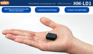
HM-LD1 is based on SPAD dToF technology and delivers real-time depth images and 3D point cloud data for accurate environmental perception. Its listed ranging capability is 0.5–25 m indoors and 0.2–8 m outdoors. The product information also highlights strong outdoor measurement performance, including accurate ranging from 8 m on a clear summer day under an assumed 80,000 lux condition. This makes the module relevant for drones that must sense nearby structures outdoors, such as bridges, expressways, dams, industrial buildings, or other assets that are difficult for people to approach.
The module is compact and lightweight, making it suitable for autonomous mobile robots with limited space for depth sensors and drones where weight affects flight distance. With UART, UDP, and UVC interfaces, HM-LD1 can be integrated with PCs, Raspberry Pi-class systems, flight-controller companion computers, and embedded platforms. MRP offers SDKs for x86 Windows, x86 Linux, and ARM Linux, supporting development across different operating systems and processor architectures.
| Specification | HM-LD1 Value | Relevance for Drones with Collision Avoidance |
|---|---|---|
| Product Name | DTOF Solid-State LiDAR HM-LD1 | Compact dToF LiDAR module for UAV, robot, and embedded perception projects. |
| Dimension | 43.5 mm × 30 mm × 26.5 mm | Small form factor supports integration into compact UAV frames and payload bays. |
| Weight | 28 g | Low weight helps preserve flight time and payload capacity. |
| Ranging Capability | Indoor: 0.5–25 m; Outdoor: 0.2–8 m | Supports close-range obstacle detection indoors and practical outdoor UAV sensing. |
| Ranging Accuracy | ±3 cm | Useful for distance thresholding, obstacle detection, and controlled approach behavior. |
| Field of View | 60° horizontal × 45° vertical | Provides directional coverage for forward, downward, or application-specific sensing. |
| Resolution | 40 × 30 | Outputs a depth grid suitable for obstacle zones, depth maps, and local perception. |
| Frame Rate | 10 fps | Provides real-time updates for low to moderate-speed UAV obstacle awareness. |
| Interface | UART / UDP / UVC | Flexible integration with flight controllers, embedded computers, PCs, and Linux platforms. |
| Operating Temperature | -20 ℃ to 60 ℃ | Suitable for many outdoor and industrial operating conditions. |
| Power Consumption | 1.2 W | Low power draw supports battery-powered UAV and robot systems. |
| Supported Development Platforms | SDKs for x86 Windows, x86 Linux, and ARM Linux | Supports development on PCs, Raspberry Pi-class systems, embedded Linux, and robotics platforms. |
View Product Details & Pricing ➔
Download the DTOF SSL HM-LD1 Product Brochure for additional product information. For engineering teams comparing depth sensors, the HM-LD1 is best understood as a compact, lightweight dToF perception module rather than a complete autonomous flight system. It provides the depth data; the UAV system still requires processing, avoidance logic, mounting design, testing, and flight-controller integration.
Engineering Checklist Before Deployment
Before deploying drones with collision avoidance, engineers should confirm that the system is matched to the mission rather than only matched to a datasheet. A good checklist reduces integration surprises and improves operational safety.
Define the flight scenario
Start by defining whether the drone will operate indoors, outdoors, in warehouses, near infrastructure, in mining environments, around trees, at low altitude, in confined spaces, or at higher speed. Each scenario changes the required sensing direction, detection distance, environmental robustness, and control behavior.
Confirm required detection range
Calculate minimum safe detection distance using UAV speed, processing latency, braking distance, and safety margin. If outdoor LiDAR range is 8 m, the drone must fly slowly enough to react within that distance. A sensor cannot compensate for an aircraft moving too fast for its sensing envelope.
Validate FOV coverage
Check whether one sensor is enough. A forward-facing sensor does not protect against side motion, backward movement, upward obstacles, or landing hazards. Review the airframe for blind zones caused by legs, propeller guards, gimbals, payloads, or mounting brackets.
Test outdoor sunlight performance
Because outdoor range can be shorter than indoor range, validate the sensor in the actual lighting conditions. Test bright sun, shade, cloudy weather, different surface colors, reflective materials, angled surfaces, and mission-specific obstacles.
Confirm interface and processing architecture
Decide whether UART, UDP, or UVC fits the system. Confirm bandwidth, latency, processor load, SDK support, operating system compatibility, and logging capability. Development convenience and final deployment reliability both matter.
Create failsafe behavior
Define what happens when depth data is missing, delayed, noisy, saturated, or outside range. A safe system should fail gracefully by slowing, stopping, hovering, alerting the pilot, or reverting to manual control depending on mission rules and platform capability.
Common Mistakes When Building Drones with Collision Avoidance
Many collision avoidance problems are caused not by bad sensors, but by incomplete system design. Here are the mistakes that show up again and again in UAV development projects.
Treating the sensor as the complete system
A LiDAR module provides depth data. It does not automatically make a drone autonomous or collision-proof. The UAV still needs algorithms, filtering, decision logic, flight-control integration, and safety validation. Buying the sensor is only the start of the work.
Ignoring speed and stopping distance
A system that works at slow speed may fail at higher speed because the drone cannot stop in time. Detection range, frame rate, latency, braking capability, and safety margin must be evaluated together. Speed limits are often necessary for reliable collision avoidance.
Using indoor test results for outdoor assumptions
Indoor testing is useful, but it is not enough for outdoor deployment. Sunlight, reflectivity, rain, fog, dust, temperature, vibration, and surface angle can change sensor behavior. Outdoor specifications and field validation are essential for industrial UAVs.
Choosing range but ignoring FOV
Long range is not enough if the sensor is not looking at the hazard. A narrow or poorly mounted sensor may miss obstacles outside its field of view. FOV, orientation, resolution, and blind-zone analysis are all part of collision avoidance design.
Forgetting weight, power, and mounting
Drone performance depends heavily on mechanical and electrical integration. Added weight can reduce endurance. Poor mounting can introduce vibration or misalignment. Power draw affects battery sizing and thermal design. A compact 28 g, 1.2 W module such as HM-LD1 helps, but integration still requires careful mechanical planning.
Not validating edge cases
Glass, black surfaces, reflective metal, thin wires, angled panels, moving people, rain, fog, dust, and direct sunlight should be tested. Edge cases often reveal whether a collision avoidance system is ready for real operations or only laboratory demonstrations.
FAQ: Drones with Collision Avoidance
What is the cheapest effective anti-collision setup for a DIY drone?
Are drones with collision avoidance reliable in industrial environments such as mining or inspection?
How important is collision avoidance compared with basic flight control?
Is LiDAR better than a camera for drone obstacle avoidance?
How much range does a drone collision avoidance LiDAR need?
Can one LiDAR sensor provide full collision avoidance for a drone?
What interface is best for integrating LiDAR into a UAV?
Can LiDAR-based collision avoidance work outdoors in bright sunlight?
What makes solid-state LiDAR useful for drones?
How should engineers test drones with collision avoidance before deployment?
📚 References & Further Reading
- Industry Standard: STMicroelectronics
- Related Guide: Drone RTK and Centimeter-Level Flight Precision






