

LiDAR Mapping for Robotics, Drones, and SLAM: How to Choose the Right Sensor for Accurate 3D Perception
LiDAR mapping has become one of the workhorse perception technologies behind autonomous robots, drones, inspection platforms, and SLAM-based navigation. Here’s the deal: if a machine has to move through the real world without bumping into things, guessing distance from a camera image alone is often not enough. Whether an AMR is threading its way between pallets in a warehouse, a UAV is holding altitude over uneven ground, or an inspection robot is building a 3D point cloud around a bridge structure, the map is only as good as the measurements feeding it. Range, accuracy, field of view, frame rate, data output, mounting position, and integration environment all matter. In the shop, choosing the wrong LiDAR does not just create a small performance gap. It can mean unstable navigation, noisy point clouds, missed obstacles, too much payload weight, awkward cable routing, or months of extra calibration work.
This guide walks through how LiDAR mapping works, how 2D and 3D LiDAR systems differ, what engineers should evaluate before choosing a sensor, and where compact solid-state dToF LiDAR modules fit into robotics, drone, and embedded vision projects. We will also look at real specifications from the DTOF Solid State LiDAR HM-LD1, including range, accuracy, field of view, resolution, interfaces, power consumption, and development support. The goal is simple: connect the theory to the kind of practical sensor-selection decisions teams actually have to make before bolting hardware onto a robot or aircraft.
Table of Contents
- 👉 What Is LiDAR Mapping?
- 👉 How LiDAR Mapping Works
- 👉 LiDAR Mapping vs Depth Sensing vs 3D Scanning
- 👉 Types of LiDAR Sensors for Mapping
- 👉 LiDAR Mapping for Robotics
- 👉 LiDAR Mapping for Drones and UAVs
- 👉 LiDAR Mapping for SLAM
- 👉 How to Choose a LiDAR Mapping Sensor
- 👉 DTOF Solid State LiDAR HM-LD1 Specifications
- 👉 Integration Workflow for Robotics and Embedded Systems
- 👉 Common LiDAR Mapping Mistakes
- 👉 LiDAR Mapping FAQ
What Is LiDAR Mapping?
LiDAR mapping is the process of using laser-based distance measurements to create a spatial representation of a real environment. Depending on the sensor and software pipeline, the output may be a 2D map, a 2.5D elevation model, a 3D point cloud, an occupancy grid, or a SLAM map that helps an autonomous system localize itself while moving. In robotics and UAV engineering, LiDAR mapping is not just a nice visualization layer. It is a practical perception layer that tells a machine where objects are, how far away obstacles sit, and how the surrounding geometry changes as the platform moves.
LiDAR Mapping in One Sentence
LiDAR mapping converts laser-based distance measurements into spatial data that machines can use to understand, navigate, and measure the physical world. A LiDAR sensor emits light, receives reflections from surfaces, and calculates distance from the returned signal. A complete LiDAR mapping system then combines those distance measurements with motion data, calibration, filtering, and software processing to generate usable maps. Look, the sensor is important, but the full system is what decides whether the map is clean enough to trust.
a short-flex design and a long-flex design for different robotics and UAV d…
Why LiDAR Mapping Matters in Industrial Automation
Industrial robots need reliable geometry, not just camera images. A mobile robot moving through a warehouse must detect pallets, shelves, walls, people, carts, lift trucks, machinery, and temporary clutter even when lighting conditions change. A drone inspecting a bridge, expressway, dam, or industrial site needs distance data to support stable flight and avoid nearby structures. A SLAM research platform needs repeated geometric observations to build a consistent map. That is why LiDAR mapping shows up in AMRs, AGVs, autonomous vehicles, inspection systems, service robots, UAVs, security devices, and embedded vision platforms.
It is also important to separate the LiDAR sensor from the LiDAR mapping system. The sensor measures distance or depth. The mapping system includes the sensor, processing hardware, coordinate frames, pose estimation, calibration, filtering, storage, and mapping algorithms. This distinction matters during procurement because a strong sensor specification does not automatically guarantee a stable map. Engineers must evaluate the full pipeline, including mechanical mounting, software support, interface bandwidth, timestamp handling, and real-world environmental performance. For a broader scanner-selection overview, see our guide on how to choose the best LiDAR scanner.
How LiDAR Mapping Works
LiDAR mapping begins with distance measurement, but a useful map requires several additional steps. The sensor has to capture depth, the software has to convert measurements into coordinates, and the system has to understand where the sensor was located when each measurement was taken. In robotics and drones, this usually means combining LiDAR data with odometry, IMU, GNSS, flight controller data, visual odometry, or SLAM algorithms. In other words, the LiDAR gives the machine geometry, but the rest of the stack gives that geometry context.
1. Laser Emission and Time-of-Flight Measurement
A LiDAR emits light toward a scene and measures the returned reflection. In Time-of-Flight systems, distance is calculated from how long the signal takes to travel to an object and return to the receiver. Direct Time-of-Flight, or dToF, measures the actual photon travel time. SPAD-based dToF architectures are designed to detect weak returned light signals, making them useful for compact depth sensing modules where size, weight, and power are under pressure.
Solid-state dToF modules such as the DTOF Solid State LiDAR HM-LD1 use SPAD dToF technology to generate real-time depth images and 3D point cloud data for perception tasks. This kind of design is especially relevant when the application needs compact size, low weight, defined interfaces, and practical integration into embedded systems. Component-level performance is influenced by photodetectors, timing circuits, optical design, signal processing, and thermal behavior. Industrial teams often review suppliers and technology references from companies such as Onsemi when evaluating sensing architectures.
2. Depth Map Generation
A depth map stores distance values across a field of view. Instead of producing one distance reading, an array-based depth sensor produces multiple distance measurements per frame. For example, a 40 × 30 resolution sensor provides 1,200 measurement cells in each frame. That is enough to understand general object shape, open space, obstacle position, and local scene structure without creating a massive processing burden. In many robots, a depth map is the first data product the software wants because it is compact, predictable, and fast to work with.
3. Point Cloud Creation
A point cloud is a set of 3D coordinates that represents surfaces observed by the sensor. Each point may include position, intensity, timestamp, confidence, or other metadata depending on the sensor and software stack. A depth frame can be transformed into a point cloud when the system knows the field of view, projection model, and calibration parameters. Point cloud density depends on resolution, FOV, frame rate, scanning method, and sensor motion. In LiDAR mapping, point clouds are used for SLAM, obstacle segmentation, object measurement, inspection, and 3D visualization.
4. Pose Estimation and Map Registration
A single LiDAR frame is only one spatial snapshot. Mapping requires knowing where the sensor was when each frame was captured. A ground robot may use wheel odometry, an IMU, visual odometry, or LiDAR SLAM. A drone may combine LiDAR with IMU data, barometer readings, GNSS, visual positioning, or flight controller attitude data. Once the system estimates sensor pose, it can register multiple frames into a larger map. Poor pose estimation can stretch, rotate, or distort a point cloud even if the LiDAR sensor itself is accurate.
5. Filtering, Calibration, and Environmental Compensation
Real-world LiDAR mapping requires filtering and calibration. Reflective metal, glass, dark rubber, sunlight, dust, vibration, and multipath reflections can all affect data quality. Filtering removes invalid readings, unstable depth values, and outlier points. Calibration aligns the LiDAR coordinate frame with the robot body, camera, IMU, map, or flight controller. Environmental compensation is especially important outdoors, where sunlight and target reflectivity can reduce effective range. A professional LiDAR mapping workflow always tests the system under real operating conditions instead of relying only on laboratory measurements.
LiDAR Mapping vs Depth Sensing vs 3D Scanning
LiDAR mapping, depth sensing, and 3D scanning are related, but they are not identical. Confusing these terms can lead teams to select a sensor that does not match the real application. A compact depth sensor can be excellent for obstacle detection, while a high-density 3D scanning system may be better for detailed surveying or digital twin creation. A LiDAR mapping system sits between the sensor and the final spatial model, using measurements over time to build useful environmental understanding.
LiDAR Mapping
LiDAR mapping builds spatial maps over time. It often involves movement, localization, registration, and software processing. In robotics, LiDAR mapping may generate an occupancy grid for navigation or a local obstacle layer for path planning. In UAV systems, it may support terrain awareness, structure inspection, or short-range obstacle awareness. In SLAM, LiDAR measurements help the system estimate both the map and the platform’s location inside that map. Here’s the deal: mapping is not just taking a pretty scan. It is turning repeated measurements into something the machine can use while moving.
Depth Sensing
Depth sensing measures distance within a local field of view. A depth sensor may output a depth image, distance matrix, or low-resolution point cloud. This is useful for obstacle avoidance, user presence detection, autofocus, volume measurement, zone intrusion monitoring, and short-range perception. Depth sensing can be part of a LiDAR mapping workflow, but by itself it does not necessarily create a map unless the data is registered across time and space.
3D Scanning
3D scanning usually focuses on high-detail capture of objects or environments. It may prioritize accuracy, density, and surface detail over real-time operation or lightweight integration. Industrial 3D scanning may use structured light, laser triangulation, photogrammetry, or high-end LiDAR. Surveying and digital twin applications often require denser data than compact embedded perception systems. That difference matters when comparing sensors because a scanner that is excellent for detailed asset capture may be too heavy, power-hungry, or slow for a small mobile robot.
| Technology Use | Main Goal | Typical Output | Common Applications |
|---|---|---|---|
| LiDAR Mapping | Create spatial maps | Point cloud, occupancy grid, SLAM map | Robotics, drones, inspection, autonomy |
| Depth Sensing | Measure local distance | Depth image, distance matrix | Obstacle avoidance, presence detection, autofocus |
| 3D Scanning | Capture detailed geometry | Dense point cloud or mesh | Surveying, reverse engineering, digital twins |
Types of LiDAR Sensors for Mapping
The right LiDAR mapping sensor depends on the required range, field of view, point density, motion conditions, mounting space, software environment, and budget. Engineers should not evaluate LiDAR only by one headline number. A sensor with long range may be too large for a drone. A dense point cloud sensor may consume too much power for an embedded robot. A compact solid-state module may be excellent for local perception but not suitable for long-range surveying. In the shop, the right answer is almost always application-specific.
2D Scanning LiDAR
2D scanning LiDAR measures distance in a single plane. It is common in indoor mobile robots, warehouse AMRs, service robots, and research platforms. A 2D LiDAR can support navigation, obstacle detection, and 2D SLAM in relatively flat environments. It can also be used for 3D mapping if the sensor is moved, tilted, rotated, or mounted on a platform that changes position. However, creating 3D data from a 2D LiDAR requires accurate timing, motion estimation, and calibration. It may also miss obstacles above or below the scan plane, which is why low overhangs, forks, tabletops, cables, and shelves can become tricky.
Mechanical 3D LiDAR
Mechanical 3D LiDAR sensors often use rotating mechanisms or multi-beam designs to produce wide 3D coverage. They are powerful tools for autonomous vehicles, outdoor mapping, high-density point clouds, and large-scale autonomy research. Their advantages include broader spatial coverage and richer 3D geometry, but they are often larger, heavier, more power-hungry, and more expensive than compact modules. Moving parts may also be a consideration in rugged embedded systems. For high-end 3D LiDAR examples in autonomy and mapping, companies such as Ouster provide useful references for multi-beam LiDAR architectures.
Solid-State LiDAR
Solid-state LiDAR avoids large spinning mechanisms, which can make it more compact and easier to integrate into robots, drones, cameras, security systems, and smart devices. Solid-state modules are attractive when the design must balance size, weight, power, durability, and cost. They can output real-time depth maps and point clouds for local perception, obstacle detection, and embedded vision development. For many industrial teams, solid-state LiDAR is not a replacement for every high-end mapping sensor, but it is a practical option where compact integration matters.
dToF LiDAR Modules
dToF LiDAR modules measure the direct travel time of light pulses. They are well suited for compact depth perception because they can deliver spatial distance data without requiring large mechanical scanning assemblies. In robotics and UAV development, dToF modules can help with obstacle avoidance, distance detection, smart inspection, user presence detection, volume measurement, and local point cloud creation. Their usefulness depends on range, FOV, resolution, frame rate, interface options, software support, and environmental robustness. Look closely at those details before assuming one compact module can cover every mapping job.
LiDAR Mapping for Robotics
Robotics is one of the strongest application areas for LiDAR mapping. Autonomous mobile robots, delivery robots, service robots, inspection robots, warehouse platforms, and research systems all need to understand surrounding geometry. Cameras can provide rich visual context, but LiDAR directly measures distance, which makes it valuable for navigation and safety-related perception. In real facilities, lighting changes, floors shine, pallets move, and people do unpredictable things. A robot needs sensing that holds up when the environment is not cooperating.
Obstacle Avoidance and Local Perception
Robots need fast local perception to avoid people, shelves, walls, pallets, forklifts, machinery, and unexpected objects. LiDAR mapping supports both static map creation and dynamic obstacle detection. A compact depth LiDAR can be mounted on the front, side, or top of a robot depending on the use case. A forward-facing sensor can detect objects in the robot’s path. A downward-angled sensor can help identify low obstacles or floor-level hazards. Multiple sensors can be combined when wider coverage is required, but every extra sensor adds mounting, synchronization, calibration, and software work.
SLAM and Autonomous Navigation
SLAM requires repeated observations of the environment. LiDAR provides reliable distance measurements in many lighting conditions where cameras may struggle, including low-texture industrial corridors, plain walls, and changing illumination. A robot may use a 2D LiDAR for global mapping and a compact depth LiDAR for local obstacle layers. In other systems, a solid-state depth module can complement wheel odometry, IMU data, and visual perception. The strongest architecture depends on required map density, robot speed, safety margin, and available compute power. The practical question is not “Which sensor is best?” It is “Which sensor gives this robot the data it needs at the right speed, weight, and integration cost?”
Robot Vision Development and Prototyping
Developers need interfaces that fit the platform. UART can be useful for embedded controllers and simple data exchange. UDP can support network-based streaming to an onboard computer. UVC can simplify PC, Raspberry Pi, and OpenCV workflows because the device can behave more like an imaging source. For developers working with computer vision pipelines, see the HM-LD1 OpenCV demo to understand how depth data can be integrated into practical software experiments. In early prototypes, an easy data path can save more time than a small improvement in a single sensor specification.
LiDAR Mapping for Drones and UAVs
Drone LiDAR mapping has different constraints than ground robot mapping. A drone sensor must be light, compact, power-efficient, and resistant to vibration. It must also perform under outdoor lighting conditions, where sunlight can affect measurement range. For UAVs, LiDAR may be used for altitude hold, terrain following, obstacle avoidance, inspection support, and short-range mapping around structures. Here’s the deal with drones: every gram and every watt shows up in flight time, payload capacity, thermal behavior, and control stability.
Altitude Hold and Terrain Following
UAVs need distance-to-ground measurement for stable altitude control, especially when flying over uneven terrain. Terrain following requires the system to update distance quickly as ground elevation changes. A lightweight LiDAR module can reduce payload impact and preserve flight endurance. Power consumption matters because every watt affects battery life. When evaluating drone LiDAR, engineers should consider sensor weight, power draw, update rate, field of view, sunlight performance, mounting angle, vibration behavior, and integration with the flight controller.
Obstacle Avoidance for Compact UAVs
Forward or downward-facing LiDAR can help drones detect walls, trees, terrain, structures, cables, or nearby surfaces. A 60° horizontal × 45° vertical FOV can support local perception in constrained flight scenarios, but the exact suitability depends on drone speed, stopping distance, control loop frequency, and mounting position. Outdoor ranging capability must be evaluated under realistic sunlight and target reflectivity. A sensor that performs well indoors may have a shorter effective range outdoors, and that difference can be critical when the UAV is moving quickly.
Inspection of Bridges, Expressways, Dams, and Industrial Sites
LiDAR can help measure distances to objects that are difficult or unsafe for people to approach, such as bridges, expressways, dams, towers, and industrial structures. The HM-LD1 product information notes accurate measurement even from 8 meters on a clear summer day, assuming 80,000 lux. This makes it relevant for short-range inspection support and distance measurement, but engineers should distinguish this from long-range surveying-grade mapping. To understand how LiDAR supports autonomous vehicle perception more broadly, see LiDAR car technology explained.
LiDAR Mapping for SLAM
SLAM, or Simultaneous Localization and Mapping, allows a robot or drone to build a map while estimating its own position inside that map. LiDAR is widely used in SLAM because it provides direct distance measurements and geometric structure. However, the sensor alone does not solve SLAM. The system also needs timing, pose estimation, coordinate frames, calibration, filtering, and loop closure logic. A clean LiDAR frame is useful. A clean LiDAR frame with a bad timestamp can still damage the map.
What SLAM Needs from a LiDAR Sensor
A LiDAR sensor for SLAM should provide repeatable geometry, stable frame rate, sufficient field of view, reliable range, low noise, and usable data output. Timestamp consistency is especially important when the platform moves quickly. If the LiDAR frame is not aligned with the odometry or IMU data, the map may become distorted. Engineers should also examine SDK access, coordinate frame documentation, ROS compatibility, and whether the sensor provides confidence or invalid-depth indicators. In the shop, debugging a SLAM problem without clear timing and calibration data can eat days fast.
2D LiDAR SLAM vs 3D LiDAR SLAM
2D LiDAR SLAM works well in many flat indoor environments such as warehouses, offices, hospitals, and logistics facilities. It is often efficient and cost-effective. 3D LiDAR SLAM is better for ramps, stairs, irregular terrain, shelves, obstacles at different heights, and UAV mapping. A 2D LiDAR can be extended into 3D mapping through motion or a tilt mechanism, but this increases calibration and synchronization complexity. A 3D depth LiDAR module provides direct depth structure, which can simplify local perception and auxiliary mapping workflows.
Using Solid-State Depth LiDAR in SLAM Pipelines
A solid-state depth LiDAR can transform depth images into point clouds and feed those points into mapping, obstacle detection, or visual-inertial pipelines. Compact depth modules are often useful for local mapping, obstacle layers, near-field perception, presence detection, and auxiliary SLAM input. For full SLAM deployment, engineers should verify whether the data stream includes the timing and calibration information required by the software stack. They should also validate performance under actual motion, vibration, and lighting conditions. Lab results are helpful, but field behavior is what decides whether the system is ready.
How to Choose a LiDAR Mapping Sensor
Choosing a LiDAR mapping sensor is an engineering decision, not just a product comparison. The right choice depends on where the system operates, what the map is used for, how fast the platform moves, how much power is available, and how the data will be processed. The following criteria help teams compare options more realistically and avoid buying a sensor that looks good on paper but causes problems on the machine.
1. Range: Indoor, Outdoor, and Real-World Reflectivity
Indoor range is usually easier because ambient sunlight is lower. Outdoor range depends on sunlight, target reflectivity, target size, incidence angle, and sensor design. Do not compare range numbers without checking test conditions. For the HM-LD1, the listed ranging capability is indoor 0.5–25 m and outdoor 0.2–8 m. That makes it relevant for compact indoor mapping, short-range outdoor perception, drone altitude support, and obstacle detection, but not for long-range surveying.
2. Accuracy and Repeatability
Accuracy affects map scale, obstacle distance, docking behavior, inspection measurements, and navigation safety margins. Repeatability is also important because SLAM algorithms rely on consistent observations. The HM-LD1 lists ranging accuracy of ±3 cm. For many compact robotics tasks, that can be useful for obstacle detection and local perception. For high-precision surveying or metrology, engineers may need denser, longer-range, survey-grade equipment. Look at accuracy together with noise, latency, calibration stability, and target material response.
3. Field of View
Field of view determines how much of the environment the sensor sees at once. A wider FOV captures more context, while a narrower FOV may be appropriate for focused forward perception. The HM-LD1 field of view is 60° horizontal × 45° vertical. This should be matched to the mounting position. A front-mounted robot sensor, downward-facing UAV sensor, and side-looking inspection sensor may all require different placement and tilt angles. Mounting is not a cosmetic detail. It decides what the sensor can actually see.
4. Resolution and Point Cloud Density
Resolution affects how much spatial detail the sensor captures. The HM-LD1 resolution is 40 × 30, which provides compact depth perception rather than dense surveying-level point clouds. This can be very useful for obstacle avoidance, distance detection, user presence detection, volume measurement, zone intrusion monitoring, and embedded perception. Higher resolution may improve detail but can increase cost, bandwidth, processing load, and power consumption. A practical system balances enough detail with enough speed and reliability.
5. Frame Rate and Motion
Frame rate affects responsiveness. The HM-LD1 frame rate is 10 fps. This can support many local perception and embedded mapping applications, but fast robots and drones should evaluate speed, stopping distance, control loop frequency, and latency. A sensor with adequate range may still be unsuitable if the update rate is too slow for the vehicle’s motion profile. When the platform moves, old data becomes stale quickly. That is where frame rate, timestamping, and control-loop design all meet.
6. Size, Weight, and Power
Drones and compact robots are constrained by size, weight, and power. The HM-LD1 weighs 28 g and lists power consumption of 1.2 W. Its dimensions are listed as 43.5 mm × 30 mm × 26.5 mm. These specifications make it attractive for embedded platforms where a large mechanical LiDAR would be difficult to mount. Engineers should still verify the final mechanical drawing, connector clearance, cable bend radius, thermal conditions, enclosure requirements, and service access before integration.
7. Interfaces and Software Support
Interface selection affects integration time. UART is useful for embedded control. UDP can support network-based data streaming. UVC can simplify camera-like depth workflows for PCs, Raspberry Pi platforms, and OpenCV experiments. HM-LD1 supports UART, UDP, and UVC interfaces, and MRP offers SDKs for x86 Windows, x86 Linux, and ARM Linux. This software support can reduce development risk for robotics, UAV, and embedded vision teams. A good interface can be the difference between a weekend prototype and a multi-week driver project.
8. Environmental Conditions
Operating temperature, sunlight, dust, vibration, reflective targets, dark targets, and mounting enclosure all affect real-world LiDAR mapping. The HM-LD1 operating temperature is listed as -20 ℃ to 60 ℃. Outdoor daytime performance should be tested under realistic lux conditions, and robots should be tested on the actual materials they will encounter. A warehouse floor, black tire, glass partition, reflective metal panel, and concrete wall may all produce different returns. Good engineers test the ugly cases early, not after deployment.
DTOF Solid State LiDAR HM-LD1 Specifications
The DTOF Solid State LiDAR HM-LD1 is a compact solid-state LiDAR module based on SPAD dToF technology. It delivers real-time depth images and 3D point cloud data for robotic perception, obstacle avoidance, distance detection, autonomous navigation, smart inspection, and embedded vision development. Its small size, low weight, low power consumption, and UART/UDP/UVC interfaces make it suitable for AMRs, drones, Raspberry Pi platforms, PCs, flight controllers, and embedded systems. Look, it is not positioned as a long-range survey scanner. It is a compact depth perception module for teams that need usable 3D sensing in a constrained mechanical design.
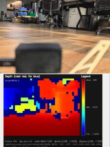
| Specification | DTOF Solid State LiDAR HM-LD1 |
|---|---|
| Technology | Solid-state LiDAR based on SPAD dToF technology |
| Dimensions | 43.5 mm × 30 mm × 26.5 mm |
| Ranging Capability | Indoor: 0.5–25 m; Outdoor: 0.2–8 m |
| Ranging Accuracy | ±3 cm |
| Field of View | 60° horizontal × 45° vertical |
| Weight | 28 g |
| Resolution | 40 × 30 |
| Frame Rate | 10 fps |
| Interface | UART / UDP / UVC |
| Operating Temperature | -20 ℃ to 60 ℃ |
| Power Consumption | 1.2 W |
| Development Platform Support | SDKs for x86 Windows, x86 Linux, and ARM Linux |
View Product Details & Pricing ➔
Where HM-LD1 Fits Best
HM-LD1 fits best where teams need compact 3D depth perception rather than long-range survey mapping. Suitable applications include compact robotics, UAV altitude hold, terrain following, robot obstacle avoidance, SLAM assistance, smart inspection, user presence detection, object recognition, volume measurement, zone intrusion monitoring, and embedded depth perception development. Its 28 g weight and 1.2 W power consumption are especially relevant for drones and small mobile platforms. Its UART, UDP, and UVC interfaces also give developers flexibility when connecting to PCs, Raspberry Pi systems, flight controllers, and embedded Linux platforms.
Where Engineers Should Validate Further
Engineers should validate HM-LD1 further when the application involves fast-motion drones, dense mapping requirements, long-range outdoor surveying, high-reflectivity targets, low-reflectivity targets, complex synchronization with IMU data, or harsh environmental exposure. The module supports real-time depth images and point cloud data, but mapping quality depends on sensor placement, host processing, calibration, motion estimation, filtering, and environmental testing. Before deployment, teams should confirm mechanical mounting, thermal conditions, cable routing, sunlight performance, vibration behavior, and software compatibility.
Download the product brochure: DTOF SSL HM-LD1 Product Brochure.
Integration Workflow for Robotics and Embedded Systems
A successful LiDAR mapping project follows a clear integration workflow. Many problems appear when teams start with a sensor purchase before defining mapping goals, data flow, calibration requirements, and test conditions. The following workflow helps reduce integration risk for robotics, drones, and embedded systems. In the shop, this is where disciplined teams save themselves from rework: define the job, mount the sensor correctly, move the data cleanly, calibrate the frames, and test under the same conditions the system will face in the field.
Step 1: Define the Mapping Goal
⚙️ The first step is to define what the system must accomplish. Obstacle avoidance, local navigation, SLAM, altitude hold, inspection measurement, presence detection, and intrusion detection require different sensor characteristics. A warehouse robot may prioritize stable local obstacle detection. A UAV may prioritize weight, outdoor range, and vibration tolerance. A research platform may prioritize raw data access and software flexibility. Without a clear goal, the sensor comparison turns into a pile of numbers instead of an engineering decision.
Step 2: Choose Sensor Placement
⚙️ Sensor placement determines what the LiDAR can see. Forward-facing mounting is common for obstacle avoidance. Downward-facing mounting supports UAV altitude measurement. Angled mounting can help detect ground obstacles. Multi-sensor layouts can increase coverage, but they also increase calibration complexity. Engineers should avoid robot body occlusion, drone landing gear obstruction, and locations where vibration or dust may reduce performance. Mount the sensor where the data will actually help the control system.
Step 3: Connect Through the Right Interface
⚙️ The interface should match the host platform and data requirements. UART may be appropriate for embedded controllers. UDP can stream data over a network to an onboard computer. UVC can simplify camera-like integration for PC, Raspberry Pi, and OpenCV workflows. Interface selection affects bandwidth, latency, driver complexity, synchronization, and debugging. It should be decided early in the architecture phase, not after the mechanical design is already frozen.
Step 4: Convert Depth Data into Point Clouds
⚙️ If the application requires 3D point cloud mapping, the software must convert depth frames into coordinates using the sensor’s projection model and calibration parameters. The pipeline should handle unit conversion, invalid depth values, coordinate frame conventions, and filtering. For many embedded applications, the system may process the depth image directly for obstacle detection and only generate point clouds when mapping or visualization is required. That choice can reduce compute load and keep the robot responsive.
Step 5: Fuse LiDAR with Motion Data
⚙️ Mapping requires motion awareness. A robot may fuse LiDAR with wheel odometry, IMU data, or visual odometry. A drone may use flight controller attitude data, barometer readings, GNSS, or visual positioning. Timestamp alignment is critical. Even small timing errors can create distorted point clouds when the platform is moving. Calibration should define the transform between the LiDAR frame and the robot, drone, camera, or IMU frame. If the transforms are wrong, the map will look wrong no matter how good the LiDAR is.
Step 6: Test in Real Operating Conditions
⚙️ Testing should include indoor lab conditions, outdoor sunlight, platform motion, reflective targets, dark targets, vibration, temperature variation, and long-duration operation. The goal is not only to confirm that the sensor works, but to confirm that the full mapping system works under deployment conditions. A LiDAR mapping pipeline that performs well on a desk may behave differently on a moving robot or vibrating drone. Field testing is where hidden assumptions get exposed.
Common LiDAR Mapping Mistakes
Many LiDAR mapping problems are caused by early selection and integration mistakes. These mistakes can lead to unstable maps, unreliable obstacle detection, or unnecessary redesign work. Avoiding them helps teams move from prototype to deployment faster. Look, most LiDAR problems are not mysterious. They usually come from skipped requirements, weak mounting, poor calibration, unrealistic range expectations, or software that was not ready for the data stream.
Mistake 1: Choosing Range Without Checking Lighting Conditions
✅ Indoor range and outdoor range are not the same. Sunlight can reduce effective measurement range, especially for compact low-power sensors. Teams should check whether the range specification applies indoors, outdoors, at night, or under a defined lux level. They should also test the exact materials and lighting conditions expected in deployment. A clean white wall in a lab is not the same target as black rubber, wet concrete, glass, brushed metal, or a dusty warehouse floor.
Mistake 2: Treating Resolution as the Only Mapping Metric
✅ Resolution matters, but it is not the only metric. Field of view, frame rate, accuracy, noise, range, interface support, latency, and software documentation all matter. A low-resolution depth sensor can still be very useful for obstacle avoidance and local perception if it is stable, lightweight, and easy to integrate. A high-resolution sensor may be unsuitable if it consumes too much power or creates excessive processing load. The right metric is whether the robot can make the correct decision on time.
Mistake 3: Ignoring Mounting Geometry
✅ Poor mounting can create blind spots and reduce mapping quality. A robot chassis can block the field of view. Drone landing gear can interfere with downward measurements. An incorrect tilt angle can miss low obstacles or waste part of the FOV on irrelevant surfaces. Mechanical design should be considered part of the perception system, not an afterthought. A well-mounted mid-range sensor often beats a poorly mounted premium sensor.
Mistake 4: Skipping Calibration
✅ LiDAR data must align with the robot frame, camera frame, IMU frame, map frame, or flight controller frame. Bad extrinsic calibration creates distorted maps and incorrect obstacle positions. Calibration should be documented, repeatable, and verified after mechanical changes. For SLAM and sensor fusion, calibration quality can be just as important as sensor accuracy. If the coordinate frames are wrong, the navigation stack will be solving the wrong problem.
Mistake 5: Buying a Sensor Without Software Support
✅ SDKs, sample code, interface documentation, operating system support, and technical support can determine how quickly a team integrates a sensor. A strong hardware specification may still create delays if the driver is difficult to use or the data format is unclear. Industrial projects should evaluate both hardware performance and integration support before final selection. A sensor that is easy to stream, debug, and calibrate often wins in real development work.
We’ve recently been testing the HM-LD1 compact dToF LiDAR in a variety of r…
LiDAR Mapping FAQ
Where can I get LiDAR maps, and can I build them myself?
Can a 2D LiDAR be used for 3D mapping?
What should I consider before choosing a LiDAR mapping system?
Is LiDAR mapping better than camera-based mapping?
What is the difference between a depth map and a point cloud?
How accurate does a LiDAR sensor need to be for robotics?
Can compact solid-state LiDAR be used for outdoor mapping?
What interfaces are useful for LiDAR mapping development?
Is LiDAR mapping suitable for SLAM in warehouses and factories?
How do I know if a LiDAR sensor is good for a drone?
Choosing the right LiDAR mapping sensor depends on the environment, required range, point cloud density, integration platform, and motion conditions. For compact robots, UAVs, embedded vision systems, and SLAM development, the DTOF Solid State LiDAR HM-LD1 provides a lightweight solid-state dToF option with real-time depth images, 3D point cloud data, UART/UDP/UVC interfaces, and SDK support for x86 Windows, x86 Linux, and ARM Linux. Review the HM-LD1 specifications or contact the technical team to confirm fit for your robot, drone, or inspection application. Look at the whole system before committing: sensor, mount, interface, calibration, software stack, test environment, and maintenance plan.
📚 References & Further Reading
- Industry Standard: Onsemi
- Industry Standard: Ouster
- Related Guide: How to Choose the Best LiDAR Scanner
- Related Guide: LiDAR Car Technology Explained
- Related Guide: HM-LD1 OpenCV Demo
- Product Resource: DTOF Solid State LiDAR HM-LD1






