GNSS Receiver Buying Guide: How to Choose the Right RTK Module for Your Project
Here’s the deal: choosing a GNSS receiver takes more work than comparing the centimeter-accuracy claim printed at the top of a data sheet. A receiver may be capable of centimeter-level positioning in a controlled test and still deliver uneven results on your machine. Frequency support, antenna construction, correction-data transport, update rate, electrical interface, power quality, mounting position, and mechanical protection all affect what you will see in the field.
Application fit matters just as much as the core receiver specification. A lightweight module that makes sense on a drone may be a poor choice for a survey installation exposed to rain, heat, vibration, and daily handling. On the other hand, a large survey-style receiver can add weight, wind resistance, and installation headaches to a compact robot without improving the part of the system that actually limits performance.
This guide starts where an engineering purchase should start: with the job. We will work through required accuracy, operating environment, correction source, host platform, interface, update rate, antenna placement, and installation constraints. We will also compare two antenna-integrated options: the compact HM-D20 for drones and robotic platforms, and the larger HM-D13 for survey-oriented integration.
Look, there is no universally “best” GNSS receiver. There is only the receiver that fits the operating requirements, integrates cleanly with the rest of the hardware, and holds up during a representative field test. The goal here is to help you build a technically defensible shortlist and account for the complete positioning system before purchase orders go out.
Table of Contents
- 👉 What Is a GNSS Receiver?
- 👉 How RTK GNSS Positioning Works
- 👉 Choose the Required Positioning Accuracy
- 👉 Frequency Bands and Satellite Constellations
- 👉 RTK Corrections, NTRIP, 4G, and LoRa
- 👉 GNSS Receiver Selection Criteria
- 👉 Recommendations by Application
- 👉 HM-D20 and HM-D13 Product Comparison
- 👉 Hardware and Software Integration Checklist
- 👉 Field Testing and Validation
- 👉 Total Cost of Ownership
- 👉 Final Buying Checklist
- 👉 Frequently Asked Question
What Is a GNSS Receiver?
GNSS stands for Global Navigation Satellite System. It is the broad term for satellite-navigation constellations including GPS, BeiDou, Galileo, GLONASS, QZSS, and IRNSS. GPS is one member of that group. People often use “GPS” as shorthand for all satellite navigation, but that distinction matters when you are reading a technical specification or confirming regional signal coverage.
A multi-constellation receiver can observe satellites from several systems at the same time. In practical terms, that can give the receiver more measurements to work with and improve satellite geometry when a building, tree line, hillside, machine frame, or other obstruction blocks part of the sky. More satellites do not guarantee a correct position, but they can give the positioning engine a better starting point.
The receiver tracks radio signals transmitted by satellites and uses their timing and orbital information to estimate position, velocity, and time. Those radio signals are extremely weak by the time they reach the ground. That is why antenna quality, placement, electrical noise, nearby transmitters, reflective surfaces, and cable losses can have such a large effect on performance.
In the shop, it is tempting to think of the receiver chipset as the whole system. It is not. Signal availability, antenna design, installation position, radio-frequency interference, satellite geometry, correction quality, mechanical stability, and software configuration all contribute to the final result. A good module installed poorly can underperform a more modest module installed correctly.
Receiver, Antenna, Correction Link, and Application Software
A working positioning system may include a GNSS antenna, receiver electronics, an RTK correction source, a communication link, a host controller, and application software. The antenna captures satellite signals. The receiver tracks those signals and calculates a navigation solution. A local base station or correction network supplies observations or corrections. Cellular service, the internet, LoRa, or another radio carries that information to the rover. A flight controller, robot computer, survey controller, or data logger then uses the receiver output.
An antenna-integrated GNSS RTK module combines some of those pieces. That can reduce component count, radio-frequency cable losses, assembly time, and connector-related failures. It can also simplify purchasing because the antenna and receiver have already been packaged together.
Do not mistake “integrated” for “complete.” An integrated module is not automatically a finished handheld survey instrument or a ready-to-fly navigation system. Buyers still need to verify power delivery, correction access, data communication, mounting, environmental protection, coordinate systems, host compatibility, and field procedures.
Standalone GNSS Versus Differential and RTK Positioning
- ✅ Standalone positioning: Uses satellite observations without live local corrections. This approach is appropriate when meter-level results meet the actual application requirement.
- ✅ Differential or sub-meter positioning: Uses correction methods designed to reduce common errors. It may be a solid fit for GIS work, inspection records, environmental observations, and asset inventories.
- ✅ RTK positioning: Uses carrier-phase observations and correction data to resolve a fixed solution. Under suitable conditions, it can provide centimeter-class positioning.
Centimeter-level positioning is conditional. It is not a blanket promise for every location, installation, correction link, weather condition, or solution state. Treat the advertised value as a capability that must be demonstrated in the intended setup.
How RTK GNSS Positioning Works
Base Station, Rover, and Correction Service
Real-time kinematic positioning normally compares observations from a rover with information from a base station whose position is known or has been established accurately. That base may be a physical receiver near the job site, or it may belong to a continuously operating reference station network. The rover receives RTCM or another supported correction stream and attempts to resolve the integer ambiguities associated with carrier-phase measurements.
Those ambiguities are one reason RTK needs more than a basic position sentence. Carrier-phase measurements are precise, but the receiver must determine the whole number of signal cycles between the satellite and antenna. When enough consistent information is available, the receiver can resolve those unknown values and report a fixed solution.
Solution status matters in day-to-day operation. A single or autonomous solution does not have an effective RTK correction result. A float solution uses correction information, but the carrier ambiguities remain unresolved. A fixed solution indicates that the ambiguities have been resolved and that the receiver can provide its expected RTK accuracy class under the current conditions.
Here is the practical point: an RTK-capable receiver is not necessarily delivering fixed RTK positioning at any given moment. Your controller and operator should know the current solution state and respond appropriately when it changes.
Why Fixed-Solution Continuity Matters
Do not evaluate a receiver only by its best static result. For a moving drone, robot, agricultural machine, or mapping vehicle, the percentage of time spent in fixed mode may be more important than one impressive coordinate measurement. Recovery speed after an interruption matters too.
A route that repeatedly changes from fixed to float near buildings, trees, fences, parked vehicles, or machinery can create inconsistent mapping and unstable guidance. If your application relies on repeatable path tracking, those transitions belong in the purchasing discussion.
A practical evaluation should record initial time to fix, the percentage of operating time in fixed mode, re-fix time after obstruction, horizontal and vertical repeatability, correction-link interruptions, and behavior while moving. Run those tests around the structures and terrain the system will actually encounter. A clear-sky demonstration in an empty field is useful, but it is not a substitute for a representative route.
RTK Does Not Eliminate Every Error Source
RTK can reduce several major common errors, but it cannot recreate satellite information that never reaches the antenna. Severe obstruction remains severe obstruction. Multipath reflections, radio interference, poor antenna placement, stale corrections, long base-to-rover distances, weak satellite geometry, vibration, and electromagnetic noise can all reduce performance.
In the shop, we sometimes see teams spend weeks tuning software when the real problem is a receiver mounted beside a switching power converter or under a carbon-fiber plate. Engineering the installation is part of engineering the positioning system. Mounting, power, grounding, cable routing, radios, and nearby materials deserve the same attention as the receiver settings.
Choose the Required Positioning Accuracy
Meter-Level and Sub-Meter Use Cases
Sub-meter positioning can be entirely adequate for utility inspection, environmental observations, general navigation, agricultural scouting, asset inventory, and GIS records. In those jobs, the operator may need to identify the correct pole, valve, tree, work zone, or equipment location without establishing a legal boundary.
Still, writing “sub-meter accuracy” in a requirement is not enough. Does it mean typical horizontal accuracy under open sky? Does it apply at a defined confidence level? Is the requirement for absolute coordinates or repeatable relative measurements? Does it include height? Those are different requirements and may lead to different hardware and procedures.
The operating environment must be part of the specification. A receiver that meets the target in open sky may not meet it beneath tree cover or beside a warehouse. A defensible requirement states the environment, confidence level, observation duration, allowable outage, and failure rate.
Centimeter-Level RTK Use Cases
Centimeter-class RTK is relevant to repeatable UAV mapping, ground-robot navigation, machine guidance, survey point collection, construction layout support, precision agriculture, and high-accuracy route mapping. These applications usually need more than a low average error. They need consistent performance and a clear indication when the solution no longer meets the required quality.
Specify horizontal and vertical requirements separately. Satellite geometry generally makes vertical positioning more difficult, so a horizontal accuracy figure should never be assumed to apply to elevation. If grading, drainage, stockpile measurement, or height clearance matters, put the vertical requirement in writing.
Accuracy, Precision, Repeatability, and Compliance
Accuracy describes how close a measured coordinate is to the correct coordinate. Precision describes the spread of repeated measurements. Repeatability tells you whether the system produces consistent results when a point or route is measured again. A system can be precise but consistently wrong because of a datum, reference-frame, antenna-height, or base-coordinate error.
Compliance is a separate matter. It covers whether the hardware, coordinate handling, metadata, calibration, procedures, documentation, and operator practices satisfy a contract or local regulation. Purchasing a centimeter-capable survey GNSS receiver does not, by itself, create a compliant survey workflow.
Frequency Bands and Satellite Constellations
Why Dual-Frequency and Multiband Tracking Matter
Measurements on multiple frequencies help a receiver estimate or reduce frequency-dependent ionospheric effects. They can also improve ambiguity resolution and shorten recovery time when conditions are favorable. This is one reason dual-frequency and multiband receivers are commonly used for modern RTK work.
Additional bands are useful, but they are not magic. They do not eliminate multipath, restore signals blocked by a roof, remove radio interference, or compensate for a poor antenna location. Think of multiband support as another tool available to the positioning engine, not a substitute for sound installation practice.
The HM-D20 provides L1/L5 dual-frequency RTK positioning. The HM-D13 supports GPS L1/L5, BeiDou B1/B2A/B2I, Galileo E1/E5, QZSS L1/L5, GLONASS G1, and IRNSS. Signal availability varies by region, constellation, receiver design, and firmware. Confirm which signals are enabled in the quoted configuration and available in the country where the system will operate.
Multi-Constellation Reception
Tracking several constellations can increase the number of usable satellites and improve observation geometry, especially when part of the sky is restricted. That can help around tree lines, equipment yards, cut slopes, and buildings where satellites in one portion of the sky are unavailable.
It does not make indoor GNSS dependable. Machines that operate in warehouses, tunnels, covered loading areas, or tightly packed urban spaces generally need complementary navigation sensors. Cameras, LiDAR, inertial sensors, wheel odometry, markers, or local radio-positioning systems may carry the navigation load when satellite signals disappear.
Channel Count in Context
The HM-D20 has 200 documented tracking channels. That number shows the receiver has capacity to track many signals, but channel count should be considered together with supported bands, acquisition behavior, firmware, correction compatibility, and field performance.
A larger channel number by itself is not a sound purchasing criterion. Demonstrated fixed-solution continuity on the intended route is worth more than an isolated number on a comparison sheet.
RTK Corrections, NTRIP, 4G, and LoRa
RTCM Compatibility
RTCM is a family of standardized messages used to carry GNSS observations and correction information. When verifying compatibility, request the exact RTCM version, message types, update intervals, and mountpoint configuration used by the correction provider. A general statement that two products “support RTCM” does not always prove they can exchange every message required by your application.
The HM-D13 documentation specifies NMEA 0183 output and RTCM input in rover mode, along with RTCM output in base mode. That documented data flow makes it relevant to base-and-rover architectures. Before ordering, confirm that the required message types, update rates, and firmware configuration are supported.
NTRIP and Cellular Corrections
NTRIP delivers correction streams over an internet connection. A real deployment may require a CORS or commercial-service account, cellular coverage, login credentials, an appropriate mountpoint, an NTRIP client, and a reliable data path from the modem or host computer into the receiver.
The correction service must also provide useful coverage and an appropriate reference frame for the work area. A receiver can process the stream correctly and still produce coordinates that do not match the project if the reference frame or datum is wrong.
The HM-D20 offers a 4G version for CORS/NTRIP use, while the HM-D13 lists 4G support as an option. Confirm what is physically included in the quotation. Ask about the modem, cellular antenna, SIM format, cable set, supported carriers, and configuration procedure. “4G capable” does not always mean every required accessory is in the box.
LoRa Correction Transport
The HM-D20 provides a LoRa option with a documented default frequency of 915 MHz, communication range up to 6 km, one-base-to-one-or-multiple-rover networking, and support for as many as 4,096 rovers. Those are useful planning figures, but actual radio performance depends on terrain, antenna height, interference, transmitter configuration, obstructions, and installation quality.
The stated rover capacity should not be read as a guarantee that 4,096 units will deliver identical simultaneous field performance in every environment. Message bandwidth, correction update intervals, channel use, packet loss, and local interference still apply.
The 915 MHz default is another item that requires attention. That frequency may not be permitted or appropriate in every country. Check regional spectrum allocations, transmitter power limits, duty-cycle requirements, antenna rules, and certification obligations before placing an order or operating the radio.
GNSS Receiver Selection Criteria
1. Required Accuracy and Solution Availability
Document horizontal accuracy, vertical accuracy, confidence level, maximum acceptable outage, and the minimum acceptable percentage of time in fixed mode. Separate open-sky specifications from requirements for the real operating route. If safety or machine control depends on GNSS, define exactly what the controller will do when correction age increases or fix quality declines.
2. Update Rate and Platform Dynamics
A higher update rate produces position solutions more often, but it does not inherently improve absolute accuracy. The HM-D20 supports a maximum update rate of 10 Hz, which is appropriate for many UAV and mobile-robot integrations. Whether 10 Hz is enough depends on platform speed, controller design, measurement latency, and the role GNSS plays in the navigation filter.
The configured baud rate, enabled messages, host processor, and timestamp handling must support the selected output frequency. If too many messages are enabled, a serial link can become congested and deliver stale information even though the receiver is calculating new positions on time.
3. Startup and RTK Initialization
The HM-D20 specifies a 28-second cold start, a 1-second hot start, and a 45-second RTK time to first fix. These figures are useful for planning, but controlled-test specifications should not be treated as guarantees after long storage, movement during startup, antenna obstruction, poor satellite geometry, or correction interruption.
Test startup behavior with the production antenna position, production power supply, and intended correction service. If the machine must be ready within a fixed time after power-up, make that an acceptance criterion rather than an assumption.
4. Antenna Design and Placement
Integrated antennas simplify component selection and avoid a separate radio-frequency cable, but they also mean the entire receiver must sit where the antenna has a useful view of the sky. The HM-D20 uses an all-in-one helical antenna design, while the HM-D13 uses an integrated mushroom-shaped antenna.
Confirm orientation and ground-plane requirements. Keep the receiver away from motors, radios, switching regulators, steel structures, and high-current conductors where practical. Nearby transmitters and noisy electronics can reduce signal quality even when the antenna appears to have a clear view.
Mechanical design should address vibration, connector retention, cable strain relief, drainage paths, and structures that may mask part of the sky. Final validation must happen with the receiver mounted on the actual vehicle, pole, tripod, or machine assembly.
5. Size, Weight, and Environmental Exposure
The HM-D20 measures Φ54.5 × 53 mm and weighs 38.2 g. That makes it the more practical candidate where payload, center of gravity, and compact installation are important. The HM-D13 measures Φ152 × 67.9 mm and weighs less than 550 g, putting it in a different mechanical class suited to larger survey-oriented, base/rover, timing, or outdoor assemblies.
The HM-D13 specifies an operating range from -40°C to 85°C and describes UV-resistant PC construction with wind and rain resistance. The supplied information does not state a formal IP rating. Do not infer one from general weather-resistance language. Request the verified enclosure rating when the installation depends on a specific level of dust or water protection.
6. Electrical and Data Interfaces
Before purchase, document supply voltage, peak current, steady-state current, logic voltage, connector family, pinout, baud rate, correction-input port, message formats, cable length, shielding, and host-side adapters. These details are basic, but they are also where many integration schedules start slipping.
The HM-D20 requires 5 V ±0.5 V, uses an 8-pin interface, supports NMEA and UBX, and includes a QMC5883L magnetometer connected through SCL/SDA. The HM-D13 provides a TTL-level UART interface at 115200 bps and documents NMEA 0183 output and RTCM data paths.
Resources from STMicroelectronics can support broader engineering work involving embedded controllers, power regulation, UART logic levels, electrical protection, and electromagnetic compatibility. This reference does not imply that STMicroelectronics endorses either receiver.
7. Sensor Fusion Requirements
GNSS provides global position, but performance can degrade around buildings, vegetation, tunnels, and indoor transitions. Mobile systems often combine GNSS with inertial sensors, wheel odometry, cameras, or LiDAR. The local sensors track short-term motion and nearby geometry while GNSS provides a global reference when signals are available.
The dToF solid-state LiDAR HM-LD1 is an example of a complementary ranging sensor, while the RoboBaton Mini stereo vision camera supports local visual depth perception.
The guide to warehouse depth camera efficiency provides more context for indoor perception workflows where satellite positioning is unavailable. Blickfeld also provides an external industry reference on the broader use of LiDAR in mapping and autonomy. These references do not imply compatibility or commercial affiliation.
Recommendations by Application
Drones and UAV Mapping
Drone integration should prioritize weight, aerodynamic placement, vibration, electromagnetic separation, update rate, correction continuity, flight-controller compatibility, and recovery after turns or temporary obstruction. Every gram matters on a small aircraft, and the receiver location can affect both satellite visibility and vehicle balance.
The 38.2 g HM-D20 is the stronger candidate of these two products when compact installation and payload control are central requirements. Its maximum 10 Hz output is also relevant to dynamic platforms. Control-loop suitability still depends on latency, synchronization, message configuration, and how the flight stack fuses GNSS with inertial measurements.
Autonomous Robots and Unmanned Vehicles
Robotic systems should be evaluated around update rate, serial interface, correction transport, heading requirements, operating speed, route obstructions, and safe behavior during GNSS degradation. A receiver that performs well in the middle of a test lot may behave differently along a metal-sided building or beneath loading equipment.
The HM-D20 includes a QMC5883L magnetometer, but a magnetometer is not the same thing as a dual-antenna GNSS heading system. Magnetic heading can be disturbed by motors, steel, permanent magnets, batteries, and current-carrying conductors. Inertial estimates and local perception may be needed to bridge interruptions and maintain reliable orientation.
Surveying and GIS Collection
Professional surveying and general GIS mapping are not interchangeable. GIS teams may accept sub-meter positioning and place more value on tablet integration, field forms, photography, cloud synchronization, and asset identifiers. Survey work may require raw observations, coordinate-system controls, antenna-height records, pole accessories, calibration procedures, stakeout software, metadata, and compliance with local requirements.
The HM-D13 is the more survey-oriented of the two modules because of its larger integrated form, documented RTCM rover and base roles, 20 ns timing specification, outdoor-construction description, and -40°C to 85°C operating-temperature range. It should not be sold or planned as a complete survey pole, controller, battery, or data-collection package unless those components are separately included and documented.
Agriculture, Logistics, and Machine Guidance
For commercial machines, repeatability, correction coverage, downtime, serviceability, and environmental protection often matter more than the smallest advertised accuracy number. Determine whether one base must support several rovers and whether cellular coverage is dependable across the entire operating area.
A private radio link can reduce dependence on mobile coverage, while a network correction service can remove the need to establish, power, secure, and maintain a local base. The right choice depends on terrain, fleet size, regional communications infrastructure, operating cost, and who will support the system after deployment.
HM-D20 and HM-D13 GNSS Receiver Comparison
Both products combine a GNSS receiver and antenna, but they address different mechanical and integration priorities. The HM-D20 emphasizes low weight, compact packaging, a 10 Hz maximum update rate, and optional 4G or LoRa correction transport. The HM-D13 emphasizes a larger survey-style integrated antenna, documented RTCM base/rover behavior, a broad operating-temperature range, and timing synchronization.
Neither profile is automatically better. The question is whether the receiver matches the platform, correction architecture, environmental exposure, and host interface. Use the documented specifications as the starting point, then verify all configuration-dependent features in the quotation.
All-in-One RTK GNSS Helical Antenna Module for Drone HM-D20
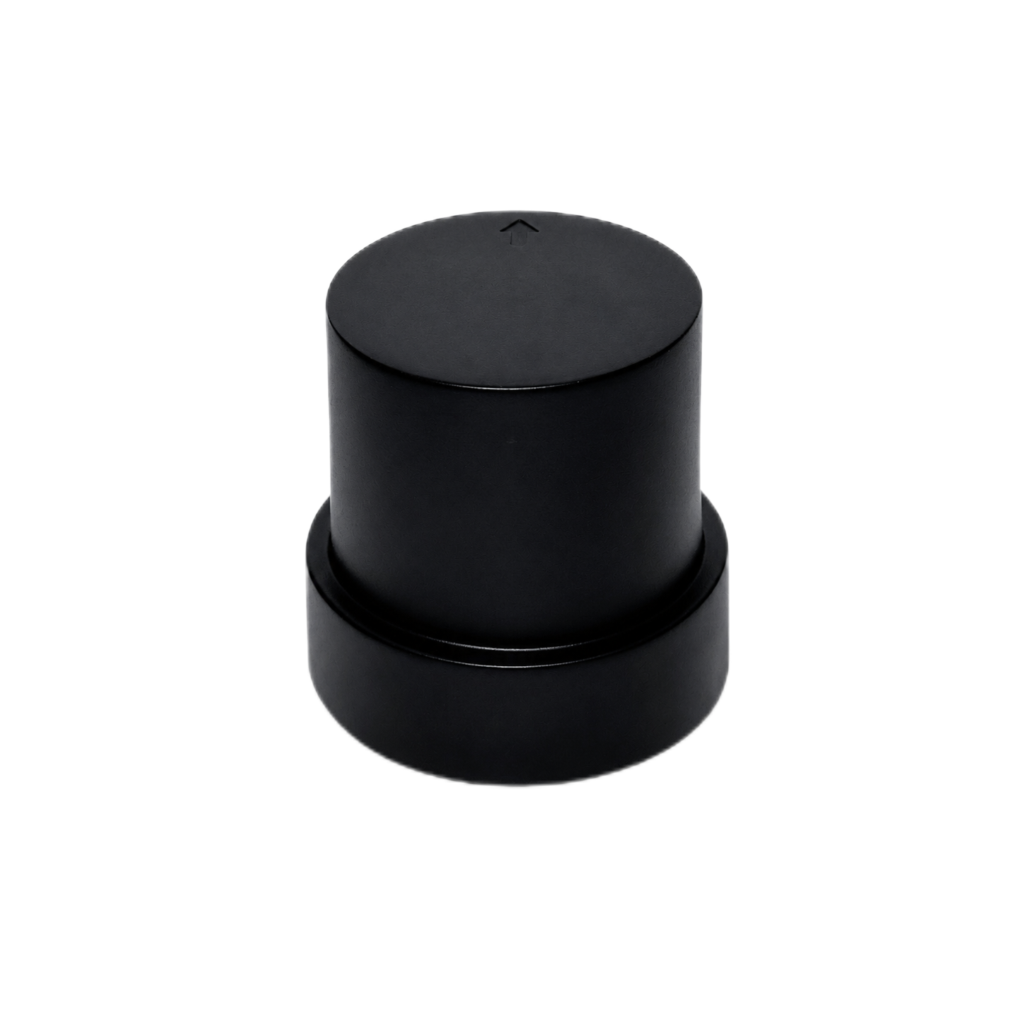
The HM-D20 is a compact dual-frequency GNSS RTK module intended for UAVs, autonomous vehicles, robotics, and survey-mapping development. Its all-in-one construction integrates the antenna, positioning electronics, and selected communication functions in a 38.2 g package. It supports GPS, BeiDou, Galileo, QZSS, GLONASS, and IRNSS, provides 200 documented tracking channels, and lists horizontal RTK accuracy of 1.0 cm + 1 ppm and vertical accuracy of 1.5 cm + 1 ppm under suitable RTK conditions.
The module supports a maximum 10 Hz update rate, a 28-second cold start, a 1-second hot start, and a 45-second RTK time to first fix. Correction options include a 4G version for CORS/NTRIP and a LoRa configuration with a default 915 MHz frequency, a stated range up to 6 km, one-to-multiple-rover networking, and support for up to 4,096 rovers. Interfaces include an 8-pin connection, NMEA and UBX data, and a QMC5883L magnetometer using SCL/SDA. The documented supply requirement is 5 V ±0.5 V.
| Positioning capability | L1/L5 dual-frequency RTK |
|---|---|
| Horizontal / vertical accuracy | 1.0 cm + 1 ppm / 1.5 cm + 1 ppm |
| Maximum update rate | 10 Hz |
| RTK time to first fix | 45 seconds |
| Satellite systems | GPS, BeiDou, Galileo, QZSS, GLONASS, IRNSS |
| Tracking channels | 200 |
| Cold start / hot start | 28 seconds / 1 second |
| Antenna system gain | 40 dB |
| Correction links | 4G CORS/NTRIP or LoRa, depending on configuration |
| LoRa details | 915 MHz default; up to 6 km; one base to one or multiple rovers; maximum 4,096 rovers |
| Dimensions / weight | Φ54.5 × 53 mm / 38.2 g |
| Operating voltage | 5 V ±0.5 V |
| Data and interface | 8-pin; NMEA; UBX |
| Magnetometer | QMC5883L using SCL/SDA |
Multiband RTK Survey Module HM-D13

The HM-D13 is a multiband RTK survey module with an integrated mushroom-shaped GNSS antenna. It supports signals from GPS, BeiDou, Galileo, QZSS, GLONASS, and IRNSS. The documented RTK specification is 1 cm + 1 ppm horizontally and 1.5 cm + 1 ppm vertically under appropriate operating conditions.
Its protocol path includes NMEA 0183 output and RTCM input in rover mode, together with RTCM output in base mode. The unit uses a TTL-level UART interface at 115200 bps, measures Φ152 × 67.9 mm, weighs less than 550 g, and specifies 20 ns timing synchronization accuracy.
The stated operating-temperature range is -40°C to 85°C. The supplied description identifies UV-resistant PC construction, resistance to long-term discoloration, and wind and rain resistance, but it does not provide a formal IP rating. An optional 4G radio module is available.
| Frequency bands | GPS L1/L5; BeiDou B1/B2A/B2I; Galileo E1/E5; QZSS L1/L5; GLONASS G1; IRNSS |
|---|---|
| RTK position accuracy | Horizontal: 1 cm + 1 ppm; vertical: 1.5 cm + 1 ppm |
| Protocols | NMEA 0183 output and RTCM input at rover; RTCM output at base |
| Baud rate | 115200 bps |
| Dimensions | Φ152 × 67.9 mm |
| Weight | Less than 550 g |
| Interface | TTL-level UART |
| Timing synchronization accuracy | 20 ns |
| Operating temperature | -40°C to 85°C |
| Communication option | Optional 4G radio module |
| Specification | HM-D20 | HM-D13 |
|---|---|---|
| Positioning | L1/L5 dual-frequency RTK | Multiband RTK |
| Satellite systems | GPS, BeiDou, Galileo, QZSS, GLONASS, IRNSS | GPS, BeiDou, Galileo, QZSS, GLONASS, IRNSS |
| RTK accuracy | H: 1.0 cm + 1 ppm; V: 1.5 cm + 1 ppm | H: 1 cm + 1 ppm; V: 1.5 cm + 1 ppm |
| Maximum update rate | 10 Hz | Not stated in supplied specifications |
| Correction options | 4G CORS/NTRIP or 915 MHz LoRa | RTCM rover input, RTCM base output, optional 4G |
| Data interface | 8-pin; NMEA; UBX | TTL UART; NMEA 0183; RTCM |
| Dimensions | Φ54.5 × 53 mm | Φ152 × 67.9 mm |
| Weight | 38.2 g | Less than 550 g |
| Operating temperature | Confirm before deployment | -40°C to 85°C |
| Best-fit profile | Weight-sensitive UAV, robotics, and embedded development | Survey-oriented, base/rover, timing, and outdoor integration |
Choose the HM-D20 when payload, compactness, documented 10 Hz output, embedded development support, or integrated 4G/LoRa correction transport drives the decision. Put the HM-D13 on the shortlist when a larger survey-style housing, TTL UART, explicit RTCM base/rover operation, a specified environmental temperature range, or timing synchronization carries more weight.
Hardware and Software Integration Checklist
Electrical Integration
Confirm voltage tolerance, peak and typical current, startup behavior, logic levels, connector orientation, grounding, shielding, and reverse-polarity protection. For the HM-D20, the documented supply is 5 V ±0.5 V through an 8-pin connection. The HM-D13 operating voltage is not stated in the supplied specifications and must be confirmed before wiring or procurement.
Power quality matters. Motors, radios, and switching loads can create noise and voltage dips that disturb sensitive receiver electronics. Test the GNSS unit from the final power architecture, including startup and worst-case load changes, rather than relying only on a clean bench supply.
Data Integration
Enable the messages the host needs instead of turning on every available output. Typical requirements include position, fix state, satellite count, correction age, dilution of precision, velocity, time, and diagnostic information.
Excessive output can consume the available serial bandwidth, especially at high update rates. Confirm baud rate, sentence length, output interval, buffering behavior, and whether correction input shares a port with navigation output. Log enough information to diagnose a field failure without overwhelming the host or storage system.
Software and Coordinate Systems
Verify NMEA or binary-protocol support, RTCM routing, NTRIP client behavior, datum, coordinate-reference system, geoid or orthometric-height handling, time synchronization, units, logging, and diagnostic access. A positioning system can appear repeatable while still reporting coordinates in the wrong frame.
The HM-D20 documentation includes development support for Raspberry Pi, Jetson Orin, and Arduino environments. Treat those resources as integration starting points. They do not prove that every operating system, carrier board, flight stack, library version, or software image will work without configuration.
Mechanical Installation
Provide an unobstructed sky view, repeatable antenna orientation, rigid mounting, suitable vibration control, weather protection, and separation from likely interference sources. Verify fastener retention and connector strain relief for mobile applications.
In the shop, a loose receiver on a bench can look excellent because it is isolated from the equipment that will eventually surround it. Approval should come from testing the final installed system. Cable routing, vehicle bodywork, radios, power converters, protective covers, and nearby structures can all change field performance.
How to Validate a GNSS Receiver in the Field
A repeatable acceptance test should represent the actual deployment. Use the production antenna position, correction source, communication link, host controller, firmware, power system, and cables. Write the pass criteria before running the test so the standard does not shift after the results are known.
- ⚙️ Establish representative routes. Include open-sky areas and the obstructions expected in normal service.
- ⚙️ Use the intended correction system. Test the production provider, base station, radio, modem, and account configuration.
- ⚙️ Record every solution state. Log fixed, float, differential, and autonomous operation instead of saving only final coordinates.
- ⚙️ Measure startup and recovery. Record initial time to fix and re-fix time after a controlled obstruction or correction interruption.
- ⚙️ Repeat static observations. Use known or independently checked points and compare horizontal and vertical results.
- ⚙️ Run moving tests. Use realistic speed, acceleration, turns, vibration, and machine operating states.
- ⚙️ Interrupt corrections briefly. Confirm system behavior during the outage and measure recovery after the stream returns.
- ⚙️ Monitor quality indicators. Track correction age, satellite count, signal quality, geometry, latency, and data-link status.
- ⚙️ Test at different times. Satellite geometry and environmental conditions change throughout the day.
- ⚙️ Keep complete logs. Preserve data needed for engineering review, supplier support, and acceptance traceability.
One successful open-sky demonstration is not enough. Acceptance thresholds should match the application. A drone may prioritize fixed-solution continuity during motion. A survey workflow may tolerate waiting at a point but require tighter coordinate repeatability. A guidance machine may need predictable degraded-mode behavior more than it needs the smallest best-case error.
The test plan should identify what happens when the criteria are not met. That includes controller behavior, operator alerts, automatic stopping rules, fallback sensors, data rejection, and requirements for repeating a measurement.
GNSS Receiver Total Cost of Ownership
Module price is only one line in the cost model. A complete system may require a correction-network subscription, SIM card, cellular data, local base-station hardware, base antenna, tripod, survey pole, power system, LoRa radios, region-appropriate antennas, USB-to-serial adapters, logic-level conversion, cables, connectors, mounts, weatherproof enclosures, controller hardware, and software licenses.
Engineering costs count too. Include electrical integration, mechanical design, protocol development, field validation, firmware maintenance, documentation, operator training, spare parts, and technical support. For a fleet, also consider provisioning, account management, replacement procedures, and version control.
A lower-priced receiver can produce a higher total project cost if it requires custom protocol work, separate communications hardware, or extensive environmental protection. An integrated module may reduce cable losses, component count, and assembly effort, but it can offer less flexibility in antenna placement. Compare the cost of a validated operating system, not receiver prices in isolation.
Final GNSS Receiver Buying Checklist
- ✅ Required horizontal and vertical accuracy.
- ✅ Maximum acceptable fixed-solution outage.
- ✅ Static or moving platform and maximum operating speed.
- ✅ Required navigation update rate and allowable latency.
- ✅ Supported constellations and frequency bands.
- ✅ Correction provider, RTCM version, and message compatibility.
- ✅ NTRIP, cellular, LoRa, or local-radio transport.
- ✅ Regional radio-frequency and certification compliance.
- ✅ Antenna type, orientation, ground-plane needs, and installation position.
- ✅ Size, weight, wind loading, and center-of-gravity impact.
- ✅ Supply voltage, startup demand, current budget, and logic levels.
- ✅ UART, USB, CAN, Ethernet, or other required interface.
- ✅ NMEA, UBX, RTCM, timing, and raw-data requirements.
- ✅ Host software, operating system, and controller compatibility.
- ✅ Coordinate-system, datum, geoid, and height requirements.
- ✅ Operating temperature and verified ingress protection.
- ✅ Cables, connectors, mounts, adapters, and accessories.
- ✅ Base-station, subscription, communications, and support costs.
- ✅ Documentation, firmware, configuration tools, and technical-support availability.
- ✅ Written field acceptance criteria and degraded-mode behavior.
Send the platform model, target accuracy, operating country, correction source, preferred interface, environmental requirements, and expected order quantity for a compatibility review and configuration-specific quotation.
GNSS Receiver FAQ
Which GNSS receiver should I buy for sub-meter GIS mapping versus centimeter-level surveying or robot navigation?
Will an RTK GNSS receiver work with my correction network, and what extra costs should I expect?
Should I choose an all-in-one handheld GNSS receiver or an integrated module for my existing hardware?
Does a dual-frequency GNSS receiver always provide centimeter accuracy?
What is the difference between NMEA, RTCM, and UBX?
How important is GNSS update rate for a drone or robot?
Can one RTK base station support multiple rovers?
What information should I send when requesting a GNSS receiver quotation?
📚 References & Further Reading
-
-
- ✅ Industry Standard: STMicroelectronics embedded design resources
-