


Tesla LiDAR Explained: Vision-Only Debate, Real-World Limits, and What Robotics Developers Can Learn
The phrase tesla lidar keeps pulling in engineers, robotics developers, investors, autonomy researchers, and plenty of curious builders because Tesla has become the loudest example of the camera-first autonomy argument. Here’s the deal: Tesla production vehicles are widely associated with a vision-first perception stack, but the LiDAR discussion refuses to go away because the rest of the autonomy world still uses direct depth sensing for mapping, validation, redundancy, obstacle detection, and safety engineering. For most serious builders, the real question is not just whether Tesla ships LiDAR on consumer vehicles. The better question is why so many autonomous machines still lean on LiDAR when the job has to work in the real world.
Look, robotics is not a clean-room debate. In the shop, on a warehouse floor, inside a factory aisle, or under a drone flying near a bridge, the right sensor stack depends on operating environment, available compute, cost ceiling, safety target, integration schedule, and the exact perception failure you are trying to solve. Camera-only systems can be impressive when they are backed by huge datasets, careful calibration, serious compute, and strong neural networks. LiDAR, on the other hand, gives you direct metric depth, which can make obstacle avoidance, navigation, altitude hold, zone monitoring, docking, and inspection a lot more straightforward. This guide explains the Tesla LiDAR debate in plain engineering terms, then turns that discussion into practical sensor-selection guidance for robotics projects using compact dToF solid-state LiDAR modules such as the DTOF Solid State LiDAR HM-LD1.
The important thing is to separate brand arguments from engineering decisions. A vehicle company building millions of cars has different constraints than a robotics team trying to get a pilot deployment working by the end of the quarter. A camera-only strategy may make sense when the platform has the data, silicon, software organization, and production economics to support it. A LiDAR-assisted strategy may make sense when a robot needs reliable distance information without asking a small team to build a massive depth-estimation pipeline from scratch.
That difference matters. A drone, AMR, inspection rover, smart camera, or embedded security device usually does not have the same data engine behind it as a major automotive manufacturer. If the system needs to know whether an object is 0.8 meters away, whether the ground is rising, whether a person entered a restricted zone, or whether a docking target is within range, direct depth can be the practical tool that gets the job done.
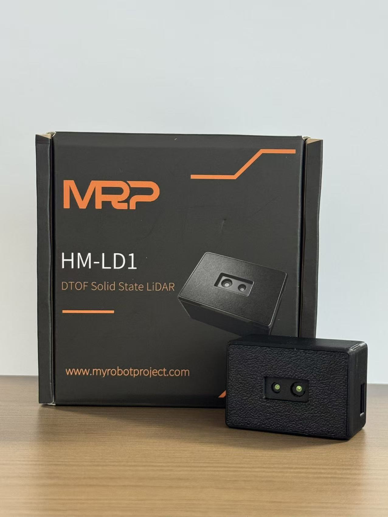
Table of Contents
- 👉 What People Mean by “Tesla LiDAR”
- 👉 Tesla’s Vision-Only Strategy Explained
- 👉 Why LiDAR Still Matters in Autonomy
- 👉 Camera-Only vs LiDAR-Assisted Perception
- 👉 Real-World Limits of Vision-Only Systems
- 👉 What Robotics Developers Can Learn
- 👉 How dToF Solid-State LiDAR Works
- 👉 DTOF Solid State LiDAR HM-LD1 Specs
- 👉 Integration Workflow for Robots and UAVs
- 👉 Industrial and Robotics Applications
- 👉 LiDAR Selection Checklist
- 👉 Common Misconceptions About Tesla LiDAR and Robotics LiDAR
- 👉 FAQ: Tesla LiDAR and Robotics LiDAR
What People Mean by “Tesla LiDAR”
When people search for “Tesla LiDAR,” they are usually mixing several questions together. Some want to know whether Tesla production cars include LiDAR sensors. Some want to know whether Tesla has ever used LiDAR for test vehicles, data collection, benchmarking, or engineering validation. Others are really asking whether a future robotaxi should use LiDAR. Robotics developers often have the most practical version of the question: if Tesla can push vision-only autonomy, does a warehouse robot, drone, inspection platform, or embedded camera system also need LiDAR?
Those questions need to be pulled apart. Production sensor strategy and engineering validation are not the same job. A company may decide not to ship LiDAR on every vehicle while still using high-precision measurement tools during development. Engineers do this all the time. They use reference sensors, motion-capture systems, calibrated targets, survey tools, ground-truth rigs, and external depth sensors to check whether the production perception system is doing what it claims. That does not mean every validation tool belongs on the final product.
Tesla Production Vehicles vs Engineering Validation
Production vehicles are built around manufacturability, cost, styling, reliability, serviceability, warranty risk, supply chain, and regulatory expectations. Engineering validation equipment is built around measurement confidence. A LiDAR unit used to compare ground-truth distance, validate object detection, build reference data, or benchmark perception performance has a different purpose than a LiDAR unit mounted on every consumer vehicle. That is why “Does Tesla use LiDAR?” is too simple for a serious engineering discussion. The stronger question is this: where does direct 3D measurement add enough value to justify cost, packaging, calibration, and integration work?
For robotics teams, that question can be easier to answer than it is in automotive mass production. A small development team usually does not have billions of miles of driving video, a massive AI training pipeline, custom autonomy silicon, or a large annotation operation. If the robot only needs to avoid obstacles, follow terrain, detect people in a zone, measure distance to infrastructure, or create a simple depth map, a compact LiDAR may reduce risk and shorten the path to a working machine.
Why the Debate Keeps Returning
The Tesla LiDAR debate keeps coming back because autonomy still gets hard at the edges. Bright sun, darkness, glare, rain, dust, glass, low-texture walls, thin obstacles, moving people, and odd road or warehouse geometry can challenge perception systems. Cameras capture rich visual information, but they do not directly encode metric distance the way a time-of-flight depth sensor does. Neural networks can infer depth from images, but that inference depends on training data, calibration, exposure, motion cues, scene structure, and model behavior.
At the same time, LiDAR has become smaller, cheaper, and more practical for non-automotive platforms. Solid-state designs and dToF modules have opened the door for drones, AMRs, smart cameras, inspection devices, security systems, and compact robots. In a practical robotics build, the question is often not whether LiDAR is philosophically necessary. The question is whether adding compact depth sensing through a module such as the DTOF Solid State LiDAR HM-LD1 solves a real problem without overloading the design.
Tesla’s Vision-Only Strategy Explained
Tesla’s vision-only strategy is usually described as a camera-first approach to autonomy. The simple version is that humans drive mainly with vision, so a sufficiently advanced machine perception system should be able to interpret roads, objects, lanes, traffic lights, pedestrians, vehicles, and motion from camera data. The engineering bet is that neural networks, temporal fusion, large-scale fleet data, and improved compute can infer the structure of the world without shipping production LiDAR.
There is a reason that idea is attractive. Cameras provide dense visual information. They capture color, texture, lane markings, signs, traffic lights, object appearance, human gestures, road context, and fine scene details. For semantic perception, cameras are extremely strong. A camera can distinguish a stop sign from a speed-limit sign, recognize a person, read lane markings, detect brake lights, classify vehicles, and interpret many visual cues that a sparse geometric sensor cannot understand by itself.
Why Cameras Are Attractive
Cameras are relatively low-cost, compact, and supported by mature automotive and consumer electronics supply chains. They can be integrated into vehicle bodies without major exterior disruption, and they provide high-resolution image data that modern neural networks can use for classification, segmentation, tracking, and scene understanding. For a company building vehicles at scale, cutting sensor cost and reducing mechanical complexity can be a major advantage if the software can meet the required performance target.
Cameras also match the current deep-learning ecosystem well. The AI world has produced powerful image and video models that can extract features, identify objects, estimate motion, and infer scene structure. With enough data, compute, validation, and engineering discipline, camera perception can become highly capable. That is the central appeal of a vision-first autonomy strategy.
How Vision Systems Estimate Depth
Camera systems estimate depth in several ways. Stereo vision compares two camera views and calculates distance from disparity. Monocular depth estimation uses learned visual cues such as object size, perspective, texture gradients, shadows, and scene context. Optical flow estimates motion between frames, while structure-from-motion uses camera movement to reconstruct geometry over time. Temporal neural networks can combine information across multiple frames to improve depth and motion understanding.
The key distinction is simple: camera systems infer distance, while LiDAR measures distance directly. In many conditions, inference works well. In other conditions, such as low texture, glare, darkness, repetitive patterns, transparent surfaces, or unfamiliar objects, inferred depth can become uncertain. A robot control loop often needs explicit distance thresholds. Stop if an object is inside a defined range. Slow down when a person enters a zone. Hold altitude above uneven terrain. Keep a fixed standoff from a wall or pipe. Direct depth makes those decisions easier to express and easier to debug.
The Engineering Bet Behind Vision-Only Autonomy
The engineering bet behind vision-only autonomy is software-heavy. It assumes that more data, larger models, better neural architectures, temporal reasoning, and fleet learning can reduce dependence on direct ranging sensors. That bet can make sense for a company with a specific vehicle platform, massive data collection, dedicated compute, and a long-term production cost strategy. It does not automatically transfer to every autonomous machine.
A university robot, factory AMR, inspection drone, or embedded security device usually has very different constraints. The team may need reliable obstacle distance this month, not after years of model training. The system may run on a Raspberry Pi, an ARM Linux board, a flight controller, or an industrial PC. In that environment, a compact depth sensor can provide immediate geometric information that complements camera-based recognition and keeps the project moving.
Why LiDAR Still Matters in Autonomy
LiDAR matters because it provides direct distance measurement. A LiDAR sensor emits light, detects reflected signals, and calculates distance based on the time required for light to travel to the target and return. Depending on the architecture, the sensor can produce depth maps, point clouds, range measurements, or 3D spatial data that software can use for mapping, navigation, object detection, safety zones, and measurement.
For broader industry context, technology providers such as AMS Osram and LiDAR companies such as Cepton Technologies show how active sensing, optical components, and LiDAR systems continue to develop across automotive, industrial, and robotics markets.
Direct Distance Measurement
Time-of-flight measurement is easy to understand at the system level. The sensor emits a light pulse, detects the reflected signal, measures travel time, and calculates distance using the speed of light. When this is repeated across a field of view, the system can generate a depth image or 3D point cloud. That direct measurement is valuable because it reduces ambiguity in jobs where distance matters more than visual appearance.
An AMR moving through a warehouse does not always need to know the brand, label, or color of a pallet wrap before slowing down. It needs to know that something physical is in the path and that the motion plan should change. A drone following terrain does not need to classify every rock, weed, roof panel, or concrete edge. It needs stable distance information so it can maintain altitude and avoid collision.
3D Structure and Obstacle Geometry
LiDAR is useful for detecting object boundaries, measuring height and width, building occupancy grids, supporting local path planning, and producing spatial representations. In robotics, that geometry is often more actionable than raw visual appearance. A robot can inflate obstacles for safety margins, segment nearby structures, decide whether a path is blocked, or track distance to a docking station.
Depth data also supports practical development. Engineers can visualize point clouds, inspect depth frames, debug obstacle zones, compare sensor readings against tape-measure checks, and tune thresholds directly. That transparency matters in industrial environments where reliability, maintainability, and safety are not optional.
Redundancy and Sensor Fusion
LiDAR is not valuable because cameras are useless. It is valuable because different sensors fail in different ways. Cameras provide semantics, color, texture, and classification. LiDAR provides metric distance and 3D structure. Radar can provide range and velocity robustness in some weather or visibility conditions. IMUs provide motion information, wheel encoders provide odometry, and GNSS or RTK can support outdoor localization.
A robust autonomy system often combines sensors so no single modality carries the whole perception burden. In robotics, sensor fusion does not have to be overly complicated. It can mean using a camera for object classification and LiDAR for distance gating. It can mean using LiDAR depth to validate visual detections. It can mean using a depth map for obstacle avoidance while a camera handles operator video. The right level of fusion depends on the machine and the job.
Camera-Only vs LiDAR-Assisted Perception
The camera-only versus LiDAR-assisted discussion should not be treated like a winner-takes-all fight. Each approach has strengths and trade-offs. A camera-only system can be excellent for semantic perception when supported by strong AI infrastructure. A LiDAR-assisted system can simplify geometric understanding and provide direct distance data, especially when a team has limited training data, limited compute, or a strict deployment timeline.
| Factor | Camera-Only Perception | LiDAR-Assisted Perception |
|---|---|---|
| Depth | Inferred through stereo, motion, or neural estimation | Measured directly through time-of-flight ranging |
| Semantics | Excellent for signs, lanes, colors, textures, and object classes | Limited semantic detail unless fused with camera data |
| Low Texture Scenes | Can struggle with blank walls, repetitive surfaces, or low contrast | Can still provide geometry if reflectivity and range are sufficient |
| Lighting Dependence | Highly dependent on visible light and exposure quality | Active sensing; performance depends on wavelength, power, reflectivity, and ambient light |
| Compute Load | Often requires heavy neural inference for depth and semantics | Adds sensor data processing but can simplify geometric detection |
| Integration Complexity | Needs calibration, image processing, and robust model training | Needs calibration, point-cloud handling, timing, and interface support |
| Best Fit | Large-scale camera AI systems and semantic-rich perception | Robots, UAVs, AMRs, safety zones, mapping, navigation, and validation |
When Camera-Only Makes Sense
Camera-only perception can make sense when the platform has strong compute, extensive training data, a carefully controlled camera layout, mature calibration processes, and a clear cost reason to avoid additional sensors. It is also appropriate when the main problem is semantic understanding: reading signs, classifying objects, interpreting color, identifying lane markings, or understanding visual scene context.
For large-scale automotive platforms, reducing hardware cost across millions of vehicles can be compelling. A camera-first strategy can also benefit from fleet learning if the organization can collect, process, label, train, validate, and deploy models at scale. That is a very different situation from a small robot project that needs dependable distance measurements in a warehouse aisle, near a conveyor, or on a drone inspection route.
When LiDAR Assistance Makes Sense
LiDAR assistance makes sense when direct depth reduces development risk. A compact LiDAR can help a robot detect obstacles, hold distance, measure height, define safety zones, assist SLAM, and validate camera-based detections. It can be especially helpful in low-texture spaces, long corridors, indoor environments, industrial facilities, drone altitude-control scenarios, and applications where the robot must react to distance thresholds.
LiDAR also makes sense when a team wants a modular path to 3D perception. Instead of building a complete neural depth pipeline from scratch, engineers can integrate a depth sensor, visualize its output, apply filtering, and connect the result to navigation or control logic. For many industrial projects, that practical workflow is worth more than copying a highly optimized automotive architecture that depends on a completely different support system.
Real-World Limits of Vision-Only Systems
Vision-only systems can be powerful, but real robotics environments are messy. Warehouses, factories, outdoor inspection sites, parking areas, corridors, construction zones, farms, and infrastructure sites all bring lighting variation, reflective materials, repeating patterns, thin obstacles, moving people, dust, and clutter. These are not rare edge cases. They are normal working conditions.
Lighting Variation
Cameras depend on exposure quality and visible light. Bright sunlight can create glare and high dynamic range scenes. Darkness can reduce detail. Backlighting can turn useful objects into silhouettes. Shadows can hide surface boundaries. LED flicker and industrial lighting can introduce artifacts. A camera system may still operate in many of these conditions, but the perception pipeline has to be built and validated for them.
Active depth sensors are not magic, and they are not immune to the environment. A LiDAR emits light and measures return signals, so performance depends on optical power, wavelength, reflectivity, ambient light, range, and sensor design. Still, in many robotics cases, active sensing can provide useful distance data even when visual appearance is hard for cameras to interpret.
Textureless and Repetitive Surfaces
Vision systems often rely on visual features. Blank white walls, glass partitions, polished floors, repeated shelving, long corridors, and uniform construction materials can reduce reliable feature extraction. Repetitive patterns can confuse matching algorithms because many parts of the scene look similar. That can affect stereo matching, visual odometry, and learned depth estimation.
LiDAR helps because it measures geometry rather than relying only on texture. If the surface reflects enough signal within the sensor’s operating range, the system can report distance even when the visual scene does not provide strong features. For AMRs, service robots, security devices, and inspection platforms, that can make obstacle detection more stable.
Scale and Distance Ambiguity
A camera image can show an object clearly without directly revealing true metric distance. A small nearby object and a large distant object can appear similar in image size. Neural networks can learn contextual cues, but robotic control usually needs explicit distance thresholds. A robot may need to know whether a person is 0.8 meters away or 2.5 meters away. A drone may need to know whether the ground is rising toward it. A docking system may need repeatable close-range measurements.
Direct depth helps translate perception into control. When software receives distance data, it can apply range thresholds, safety margins, obstacle inflation, and control rules directly. That does not remove the need for testing, but it simplifies the path from sensing to action.
Edge Cases for Robots and UAVs
Robots run into thin chair legs, forklift forks, hanging cables, transparent barriers, pallet wrap, moving people, dust, outdoor glare, uneven floors, reflective metal, and fast approach speeds. UAVs add vibration, payload limits, battery limits, changing altitude, outdoor sunlight, and limited onboard compute. A perception stack that behaves in a lab can fail when mounted on a moving platform in a real facility.
Direct depth can support stop zones, collision avoidance, follow-distance logic, terrain following, landing assistance, docking, and virtual safety envelopes. It also gives engineers a useful debugging signal. When a robot behaves badly, the team can inspect depth frames or point clouds to see whether the sensor saw the obstacle, whether filtering rejected it, or whether the control logic made the wrong decision.
What Robotics Developers Can Learn from the Tesla LiDAR Debate
The main lesson is that sensor strategy depends on system constraints. Tesla’s approach is shaped by its vehicle architecture, production economics, software strategy, training data, compute platform, and long-term autonomy goals. A robotics startup, research lab, UAV integrator, factory automation team, or embedded vision developer works under different constraints. Copying an automotive sensor philosophy without copying the surrounding infrastructure is a good way to create unnecessary risk.
Lesson 1 — Sensor Strategy Depends on System Constraints
Every sensor decision should begin with the application. A warehouse AMR may prioritize near-field obstacle detection, people safety, and docking. A drone may prioritize weight, power, altitude hold, and terrain following. A security system may prioritize presence detection and zone intrusion. An inspection robot may prioritize distance measurement around bridges, expressways, dams, or industrial equipment. These machines do not need the same sensor stack.
Instead of asking whether LiDAR is universally necessary, ask what failure mode the robot must solve. Is the camera struggling in low texture? Is distance estimation unreliable? Is the robot missing thin obstacles? Is the drone unstable over uneven terrain? Is the safety zone producing false alarms? If direct metric depth addresses the failure mode, LiDAR may be justified.
Lesson 2 — Direct Depth Can Reduce Development Risk
Direct ranging can reduce the need to solve every perception problem with AI. A compact LiDAR can provide immediate distance data for obstacle detection, height measurement, zone monitoring, and environmental perception. That is especially useful for teams that need prototypes, pilot deployments, or customer demonstrations quickly.
For compact robotics and UAV prototypes, the DTOF Solid State LiDAR HM-LD1 is designed for real-time depth images and 3D point cloud data in space-constrained systems. By using a direct depth module, teams can focus on application logic, mounting, filtering, and safety validation instead of building an entire depth-estimation model from camera data.
Lesson 3 — Modularity Matters
Robotics developers benefit from modular sensors with flexible interfaces. UART can support lightweight embedded communication. UDP can support networked data streaming. UVC can support PC-style camera workflows. SDK support for x86 Windows, x86 Linux, and ARM Linux can reduce integration friction across development environments.
Modularity also supports experimentation. A team can test a LiDAR module on a desktop, then move it to a Raspberry Pi, embedded Linux system, robot controller, or drone platform. The ability to evaluate depth data quickly can shorten design cycles and improve confidence before committing to mechanical packaging or production integration.
Lesson 4 — Use LiDAR Where It Adds Measurable Value
LiDAR should not be added blindly. It should solve a defined problem. If a camera system already meets safety, reliability, cost, and performance requirements, extra hardware may not be necessary. But if the robot needs direct distance information, robust zone detection, easier obstacle geometry, or lower development risk, LiDAR can be a practical addition.
If your robot or UAV needs direct depth sensing for obstacle avoidance, navigation, or inspection, compare compact dToF LiDAR options such as the DTOF Solid State LiDAR HM-LD1. For related system planning, teams can also review robotics perception modules, UAV navigation sensors, or contact our engineering team for integration support.
How dToF Solid-State LiDAR Works
dToF stands for direct time-of-flight. In a dToF LiDAR system, a light pulse is emitted, photons reflected from the target are detected, and the system measures how long the light took to travel to the object and return. Because the speed of light is known, the travel time can be converted into distance. When this measurement is performed across multiple pixels or sensing points, the result can be a depth image or point cloud.
Direct Time-of-Flight Principle
The direct time-of-flight principle is valuable because it measures distance directly rather than estimating it only from visual cues. The sensor does not need to understand whether the object is a pallet, wall, person, or machine before measuring range. It detects reflected light and calculates distance. That makes dToF especially useful for obstacle avoidance, range detection, and depth-aware control.
In practice, engineers still need to handle invalid readings, reflectivity differences, ambient sunlight, minimum and maximum range limits, and filtering. No sensor gets a free pass. But the underlying signal is direct distance measurement, which can be easier to integrate into robotic control logic than inferred monocular depth.
SPAD-Based Detection
SPAD sensors, or single-photon avalanche diodes, are highly sensitive photon detectors used in some compact dToF LiDAR designs. At a high level, SPAD-based detection supports measurement of very small light returns, allowing compact solid-state modules to generate depth information. For robotics developers, the important point is not the semiconductor physics alone. The practical result is small form factor, active depth sensing, and real-time data output suitable for embedded systems.
SPAD dToF LiDAR can be a good fit when the platform needs direct range data but cannot carry a large scanning LiDAR. Drones, small AMRs, smart inspection tools, cameras, and security devices often need low weight, low power, and simple mechanical integration. Solid-state modules help meet those constraints.
Depth Map vs Point Cloud
A depth map is a two-dimensional grid where each pixel represents distance. Developers can process a depth map almost like an image: threshold it, segment regions, detect near objects, or combine it with RGB imagery. A point cloud represents 3D spatial coordinates, usually described as X, Y, and Z positions. Point clouds are useful for mapping, SLAM, obstacle geometry, and spatial visualization.
Depth maps are often convenient for embedded perception because they are compact and image-like. Point clouds are more directly spatial and can be used for 3D mapping and navigation. A module that supports real-time depth images and point cloud data gives developers flexibility across both approaches.
Why Solid-State Matters
Solid-state LiDAR matters because it avoids large spinning mechanical assemblies. That makes it more suitable for compact robots, drones, embedded platforms, inspection tools, smart cameras, and security devices. Smaller sensors are easier to mount, easier to protect, and less disruptive to product design. They also fit platforms where weight and power are tight.
For many non-automotive applications, the goal is not to create a long-range autonomous vehicle perception suite. The goal is to add practical depth sensing to a product with limited space and power. Solid-state dToF modules are built for that kind of trade-off.

DTOF Solid State LiDAR HM-LD1 Specs
The DTOF Solid State LiDAR HM-LD1 is a compact SPAD dToF LiDAR module for robotics, UAVs, embedded vision, inspection, security, and distance detection applications. It outputs real-time depth images and 3D point cloud data, supports multiple interfaces, and is designed for teams that need direct distance measurement without adding a large mechanical LiDAR unit. Its compact housing and low weight make it suitable for autonomous mobile robots with limited space for depth sensors, as well as drones where payload affects flight time.
HM-LD1 supports ranging for indoor and nighttime conditions up to 25 meters and outdoor daytime environments up to 8 meters. Its reported ranging accuracy is ±3cm, and it provides a 60° horizontal by 45° vertical field of view. With UART, UDP, and UVC interfaces, it can be integrated with PCs, Raspberry Pi platforms, flight controllers, embedded systems, and development workflows that require either lightweight communication or camera-style data access. MRP also offers SDKs for x86 Windows, x86 Linux, and ARM Linux, enabling development across common robotics and embedded platforms.
View product details: DTOF Solid State LiDAR HM-LD1
Download technical brochure: DTOF SSL HM-LD1 Product Brochure
| Specification | DTOF Solid State LiDAR HM-LD1 |
|---|---|
| Technology | SPAD dToF solid-state LiDAR |
| Dimension | 43.5mm × 30mm × 26.5mm |
| Ranging Capability | Indoor: 0.5–25m; Outdoor: 0.2–8m |
| Ranging Accuracy | ±3cm |
| Field of View | 60° horizontal × 45° vertical |
| Resolution | 40 × 30 |
| Frame Rate | 10fps |
| Interface | UART / UDP / UVC |
| Operating Temperature | -20℃ to 60℃ |
| Power Consumption | 1.2W |
| Weight | 28g |
| Development Platform Support | SDKs for x86 Windows, x86 Linux, and ARM Linux |
View Product Details & Pricing ➔
What These Specs Mean for Developers
The 60° horizontal by 45° vertical field of view is useful for forward obstacle sensing, short-range environment awareness, and zone monitoring. It gives a compact robot or embedded system a defined depth window without requiring a large scanning mechanism. For AMRs, this can support local obstacle detection. For smart cameras or security systems, it can support presence detection and restricted-area monitoring. For drones, it can help with low-altitude awareness when mounted and calibrated correctly.
The 40 × 30 resolution is appropriate for compact depth perception tasks where low power, small size, and simple integration matter more than dense automotive-grade point clouds. Developers should match resolution to the task. If the goal is to detect a large nearby obstacle, monitor a zone, estimate distance to a surface, or assist embedded perception, a lower-resolution depth map may be sufficient. If the goal is dense 3D reconstruction of complex scenes, a higher-resolution sensor may be required.
The 10fps frame rate can support many mobile robot, inspection, presence detection, and embedded perception use cases. Teams working on fast UAVs, high-speed AMRs, or safety-critical control loops should validate whether 10fps meets their latency and stopping-distance requirements. Sensor choice should always be matched to robot speed, braking distance, processing latency, and safety margin.
The 1.2W power consumption and 28g weight are important for battery-powered platforms. Drones and compact robots are highly sensitive to payload and power budget. A small, low-power LiDAR module can add depth sensing without the packaging and energy burden of a larger sensor. The UART, UDP, and UVC interfaces support different integration paths, from embedded serial data to networked streaming and PC-style camera workflows.
Integration Workflow for Robots and UAVs
Integrating LiDAR into a robot or UAV should begin with the perception task, not the sensor datasheet. Define what the system must detect, how quickly it must react, what distance thresholds matter, what compute platform is available, and what failure modes must be reduced. A clear integration workflow prevents wasted effort and helps engineers prove whether the sensor solves the actual problem.
⚙️ Step 1 — Define the Perception Task
Common perception tasks include obstacle avoidance, docking, altitude hold, terrain following, SLAM assistance, intrusion detection, presence detection, distance measurement, volume measurement, and inspection. Each task has different requirements. Docking may require repeatability at close range. UAV altitude hold may require stable vertical distance data. Zone intrusion may require reliable detection inside a defined area. Inspection may require distance measurements to hard-to-access structures.
Once the task is defined, engineers can determine the required range, field of view, frame rate, accuracy, mounting location, and interface. This prevents overbuying sensors for simple tasks or under-specifying sensors for demanding ones.
⚙️ Step 2 — Choose Data Output
Depth maps are useful for image-like processing. A developer can apply thresholds, masks, filters, and region detection. Point clouds are useful for spatial mapping, SLAM, obstacle geometry, and visualization. UART may be suitable for lightweight embedded systems. UDP can support networked data streaming. UVC can simplify PC-style camera workflows and rapid prototyping.
The best output depends on the software stack. A ROS-based robot may prefer point-cloud or depth-image integration. A microcontroller-based system may prefer simplified distance data over UART. A vision application running on a PC may prefer UVC. Flexible interfaces reduce integration risk because the same sensor can support multiple development paths.
⚙️ Step 3 — Mounting and Calibration
Mounting affects perception quality. Engineers should consider sensor height, tilt angle, coordinate frame, field-of-view coverage, vibration, lens or window cleanliness, and physical protection. A forward-facing sensor on an AMR should cover the expected obstacle zone. A downward-facing sensor on a drone should be positioned to avoid propeller interference, vibration, and blocked field of view.
If the LiDAR is fused with an RGB camera, IMU, wheel odometry, or another sensor, extrinsic calibration becomes important. The system must know the spatial relationship between sensors. Poor calibration can cause correct depth measurements to be interpreted in the wrong coordinate frame, leading to navigation errors.
⚙️ Step 4 — Filter and Validate Depth Data
Depth data should be filtered and validated before it controls a robot. Developers should handle invalid pixels, reflective surfaces, ambient sunlight, minimum and maximum range thresholds, temporal smoothing, obstacle clustering, and safety margin inflation. The filtering strategy should match the application. A safety zone may prioritize conservative detection. A mapping system may prioritize stable geometry. A drone may prioritize low latency.
Validation should include real operating environments, not just lab tests. Test against walls, people, pallets, cables, reflective materials, outdoor light, vibration, and expected robot speeds. The goal is to understand not only when the sensor works, but how it fails and how the system should respond.
⚙️ Step 5 — Fuse With Other Sensors
LiDAR can be fused with RGB cameras, IMUs, wheel odometry, ultrasonic sensors, radar, GNSS, RTK, and optical flow. Sensor fusion does not always need to be complex. A simple system may use LiDAR for distance thresholds and a camera for object recognition. A more advanced system may combine LiDAR point clouds with odometry for mapping. A drone may combine LiDAR altitude readings with IMU and optical flow for more stable low-altitude flight.
The goal of fusion is to combine complementary strengths. Cameras help answer what the object may be. LiDAR helps determine where it is and how far away it is. Odometry estimates robot motion. IMUs capture acceleration and orientation. GNSS or RTK supports outdoor positioning. The correct combination depends on the deployment environment.
Industrial and Robotics Applications
LiDAR is valuable across many non-automotive applications because robots need to understand space. Whether the platform is a mobile robot, drone, smart camera, inspection device, or security system, direct depth can support safer movement, better measurement, and more reliable automation. The Tesla LiDAR debate is interesting, but the immediate industrial question is how to make real robots work in real spaces.
Autonomous Mobile Robots
Autonomous mobile robots can use LiDAR for obstacle detection, local navigation, docking, safety zones, shelf detection, pallet detection, corridor perception, and SLAM assistance. In warehouses and factories, visual scenes may include repeated shelving, low-texture walls, reflective floors, moving workers, and dynamic equipment. Direct depth can help AMRs maintain safe distances and detect physical structures even when visual classification is difficult.
For compact AMRs, sensor size and power consumption matter. A small dToF LiDAR module can fit into constrained enclosures and provide depth information without adding significant payload. This can be useful for development platforms, service robots, delivery robots, and industrial prototypes.
UAVs and Drones
Drones can use LiDAR for altitude hold, terrain following, landing assistance, low-altitude obstacle detection, and inspection around bridges, expressways, dams, and infrastructure. Weight and power are critical in UAV design because every gram affects flight time and every watt affects battery budget. A 28g module with 1.2W power consumption can be attractive for platforms that need depth sensing without a large payload penalty.
Outdoor use should be validated carefully because sunlight, reflectivity, speed, vibration, and mounting angle all affect performance. HM-LD1 is specified for outdoor ranging up to 8 meters, which can be relevant for inspection and moderate-distance detection under appropriate conditions. Teams should test the exact mission profile before relying on any sensor for flight-critical control.
Smart Inspection
Inspection applications often require distance measurement to structures that are difficult or unsafe for people to approach. Bridges, expressways, dams, industrial equipment, storage tanks, and elevated surfaces can all benefit from depth-aware sensing. A compact LiDAR can help maintain standoff distance, measure object range, and provide spatial context for inspection cameras.
Depth data can also improve repeatability. If an inspection robot can maintain a consistent distance from a surface, image quality and measurement consistency may improve. When combined with cameras, LiDAR can help connect visual defects or inspection targets to physical location and distance.
Cameras and Autofocus
Smart cameras can use depth data for distance-assisted autofocus, user presence detection, subject distance measurement, and object recognition support. A camera alone may need to infer distance from image sharpness, scale, or learned cues. A depth sensor can provide direct range information that helps the system respond faster or more reliably.
In embedded vision products, depth can also support privacy-conscious presence detection because the system may not need to rely only on identifiable visual imagery. A depth map can indicate whether a person or object is in a zone without requiring detailed texture or color data for every use case.
Security and Zone Intrusion
Security systems can use 3D depth for zone monitoring, people or object presence, false alarm reduction, restricted-area detection, and virtual fences. Traditional motion detection can be affected by lighting changes, shadows, reflections, or camera noise. Depth-based detection can add spatial constraints, helping the system determine whether an object is actually inside a defined zone.
For compact robots, drones, and embedded vision systems that need real-time depth images and 3D point cloud data, explore the DTOF Solid State LiDAR HM-LD1.
LiDAR Selection Checklist for Robotics Developers
Selecting LiDAR for robotics should be a structured engineering process. A sensor that looks impressive on paper may be wrong for the platform if it is too heavy, consumes too much power, lacks the right interface, or does not support the required range. A compact sensor with modest resolution may be ideal if it solves the specific perception task reliably.
✅ Range
Define the minimum and maximum useful detection distances. A robot may need near-field detection for slow navigation, while an outdoor inspection system may need several meters of range. Consider whether the application is indoor, outdoor, nighttime, or mixed. HM-LD1 is specified for indoor ranging from 0.5 to 25 meters and outdoor ranging from 0.2 to 8 meters, so teams should evaluate whether those ranges match their operating environment.
✅ Accuracy
Determine whether ±3cm accuracy is sufficient for the application. Rough obstacle avoidance may tolerate more error than precision docking or dimensional measurement. If the task is safety-related, accuracy should be evaluated together with latency, filtering, mounting, calibration, and control response.
✅ Field of View
Field of view determines the area the sensor can observe. A forward-facing AMR may need enough horizontal coverage to detect obstacles in its path. A drone may need vertical coverage for terrain changes or landing assistance. A fixed security system may need coverage of a defined zone. HM-LD1’s 60° horizontal by 45° vertical field of view is suitable for many compact sensing applications, but placement and orientation are critical.
✅ Resolution and Frame Rate
Resolution and frame rate should match object size and robot speed. A 40 × 30 depth map may be sufficient for presence detection, obstacle zones, and compact depth awareness, but it is not intended to replace high-density mapping LiDAR in every application. A 10fps frame rate can work for many inspection and mobile robot tasks, but high-speed systems require careful validation of reaction time and stopping distance.
✅ Interface and Platform
Check whether the system uses Linux, Windows, ARM Linux, Raspberry Pi, embedded MCU, industrial PC, or a flight controller. Interface compatibility can determine integration speed. UART, UDP, and UVC support gives developers multiple options. SDK support for x86 Windows, x86 Linux, and ARM Linux can reduce software friction during prototyping and deployment.
✅ Size, Weight, and Power
Battery-powered robots and drones must account for sensor weight and power consumption. A 28g module with 1.2W power consumption is practical for many compact platforms. Mechanical packaging should also consider heat, vibration, cable routing, protective windows, and field-of-view clearance.
✅ Environmental Conditions
Consider bright outdoor light, reflective surfaces, dust, vibration, operating temperature, and mechanical protection. HM-LD1 is specified for -20℃ to 60℃ operation. Real-world testing should include the expected environment, not only ideal indoor conditions. If the robot will operate in harsh industrial settings, engineers should validate performance under dust, vibration, sunlight, and surface reflectivity variations.
Common Misconceptions About Tesla LiDAR and Robotics LiDAR
The Tesla LiDAR debate often creates oversimplified conclusions. Some readers assume that if Tesla does not use LiDAR in production vehicles, no robot needs LiDAR. Others assume LiDAR automatically solves autonomy. Both views miss the point. Sensor selection is an engineering trade-off, not a brand loyalty question.
“If Tesla Does Not Use LiDAR, Robots Do Not Need It”
Automotive production strategy does not automatically transfer to industrial robotics. Tesla’s system is shaped by vehicle-scale packaging, dedicated compute, large data pipelines, and a specific driving task. A warehouse AMR, inspection drone, security camera, or embedded robot has different constraints. Many robotics teams need direct depth now, without building a massive visual AI pipeline.
“LiDAR Replaces Cameras”
LiDAR does not replace cameras for semantic understanding. Cameras remain strong for labels, signs, colors, textures, object classification, and human interpretation. LiDAR adds metric depth and 3D structure. In many systems, the strongest approach is not camera versus LiDAR, but camera plus LiDAR, each used for what it does best.
“Cheaper LiDAR Means Easy Integration”
Lower hardware cost does not remove the need for calibration, filtering, data handling, mechanical mounting, software integration, and safety validation. Engineers still need to define coordinate frames, manage invalid data, test environmental performance, and connect depth output to control logic. A good sensor can reduce development burden, but it does not eliminate engineering discipline.
“More Resolution Is Always Better”
More resolution is not always better. Resolution should match the task. A small, low-power 40 × 30 depth sensor may be more appropriate than a dense, expensive sensor for short-range obstacle detection, presence sensing, embedded development, and compact UAV applications. Higher resolution can increase data volume, processing load, cost, and integration complexity. The best sensor is the one that meets requirements with acceptable margin.
Build Practical Depth Sensing Into Your Robot or UAV
The Tesla LiDAR debate shows that sensor strategy depends on system goals. For robotics developers who need compact, low-power, direct depth sensing, the HM-LD1 provides real-time depth images, 3D point cloud data, UART/UDP/UVC interfaces, and SDK support for x86 Windows, x86 Linux, and ARM Linux. Instead of treating LiDAR as an abstract automotive argument, teams can evaluate it as a practical engineering tool for obstacle avoidance, navigation, inspection, presence detection, and embedded perception.
FAQ: Tesla LiDAR and Robotics LiDAR
Does Tesla use LiDAR, and why do people keep debating it?
Is LiDAR vs camera-only still relevant for autonomous systems?
Why not add LiDAR if prices are falling?
What is dToF LiDAR, and why is it useful for robotics?
Is the DTOF Solid State LiDAR HM-LD1 suitable for drones and AMRs?
📚 References & Further Reading
- Industry Standard: AMS Osram
- Industry Standard: Cepton Technologies
- Related Guide: DTOF Solid State LiDAR HM-LD1
- Related Guide: DTOF SSL HM-LD1 Product Brochure






