

LiDAR Jammer vs LiDAR Sensor Interference: What Robotics Buyers Must Know Before Choosing 3D Sensing Hardware
Searches for lidar jammer tend to throw a lot of unrelated issues into one bucket: traffic-enforcement countermeasures, laser detectors, spoofing, sunlight interference, multi-LiDAR crosstalk, weak outdoor ranging, and plain old robotics perception problems. Here’s the deal: those are not the same thing. For industrial buyers, that confusion can send a project down the wrong purchasing path fast. A LiDAR jammer is generally understood as a device intended to interfere with measurement equipment, and that can be illegal or restricted in many regions. A robotics LiDAR module, on the other hand, is built to create depth maps, point clouds, distance readings, and navigation data so machines can work safely and predictably.
This guide separates unsafe or legally sensitive jamming topics from the real engineering problem most buyers are trying to solve: choosing a LiDAR sensor that still gives useful data in bright light, tight robot housings, drones, embedded systems, and multi-sensor environments. Using the DTOF Solid state LiDAR HM-LD1 as a practical reference point, we will compare LiDAR jamming, LiDAR interference, dToF sensing, outdoor ranging limits, sensor integration requirements, and the specifications robotics buyers should verify before committing to hardware.
Look, in the shop or out in the field, the real question usually is not “How do I jam LiDAR?” The real question is “Why are my readings unstable, and what kind of sensor should I buy so my robot does not behave like it is guessing?” That means looking at range, field of view, frame rate, sunlight tolerance, mounting geometry, power quality, interface support, software tooling, and the actual surfaces the machine will see every day.
A good LiDAR buying decision starts with plain language. If your team needs obstacle avoidance, UAV altitude sensing, people detection, docking assistance, zone monitoring, or basic 3D awareness, you need legitimate sensing hardware. If your team is worried about interference, you need testing and integration discipline. You do not need vague countermeasure hardware that creates legal and safety exposure while doing nothing useful for robot perception.
Full LiDAR setups are powerful — but often too heavy, too complex, or just …
Table of Contents
- 👉 Quick Answer: LiDAR Jammer vs LiDAR Sensor Interference
- 👉 What Is a LiDAR Jammer?
- 👉 Legal, Safety, and Compliance Context
- 👉 What LiDAR Interference Means in Robotics
- 👉 How dToF Solid-State LiDAR Works
- 👉 How Robotics Buyers Should Evaluate LiDAR Hardware
- 👉 Product Example: DTOF Solid State LiDAR HM-LD1
- 👉 Integration Planning for Robots, UAVs, and Embedded Systems
- 👉 Industrial Application Scenarios
- 👉 Comparison: Jammer, Detector, and Robotics LiDAR Sensor
- 👉 Procurement Checklist for B2B Buyers
- 👉 FAQ: LiDAR Jammer, Interference, and Robotics LiDAR
Quick Answer: LiDAR Jammer vs LiDAR Sensor Interference
The short answer for robotics buyers
A LiDAR jammer is not a robotics LiDAR sensor. A jammer is generally described as an active interference device intended to disrupt a measurement system, often in traffic-enforcement or adversarial sensing discussions. A robotics LiDAR sensor has the opposite job: it measures distance and provides useful perception data for navigation, obstacle avoidance, presence detection, mapping support, safety zones, and embedded machine vision. When engineers search for lidar jammer, they may actually be trying to solve an interference problem such as poor outdoor ranging, bright sunlight noise, reflective floors, glass, multi-sensor crosstalk, or inconsistent data from an embedded host system.
A LiDAR jammer is not a robotics LiDAR sensor. A jammer attempts to interfere with a measurement device and may be illegal or restricted. Robotics LiDAR sensors are used for depth sensing, obstacle avoidance, SLAM support, navigation, presence detection, and industrial perception. If your concern is reliability, evaluate sunlight performance, ranging accuracy, field of view, interfaces, SDK support, and embedded platform compatibility.
Why the distinction matters in procurement
For procurement teams, the wording in a requirement can shape the entire supplier search. If the real requirement is “avoid unreliable LiDAR readings outdoors,” the answer is not a jamming device. The answer is a documented 3D sensing module with known range, field of view, frame rate, power consumption, operating temperature, data interfaces, software support, and integration guidance. The DTOF Solid state LiDAR HM-LD1, for example, is a compact dToF solid-state LiDAR module with indoor ranging of 0.5–25m, outdoor ranging of 0.2–8m, ±3cm accuracy, 60° horizontal by 45° vertical FOV, UART/UDP/UVC interfaces, 1.2 W power consumption, and SDK support for x86 Windows, x86 Linux, and arm Linux.
In an industrial buying meeting, that difference matters. A purchasing spec that says “LiDAR jammer resistance” may send suppliers in one direction. A spec that says “stable outdoor dToF depth sensing under high ambient light with documented SDK support” sends them in a much better direction. One phrase sounds like a countermeasure discussion. The other sounds like a real engineering requirement that can be tested, quoted, integrated, and supported.
What Is a LiDAR Jammer?
Basic definition
A LiDAR jammer is generally understood as an active device designed to emit signals or light pulses that interfere with another LiDAR-based measurement system. In consumer search contexts, the phrase is often associated with traffic enforcement countermeasures. In industrial and autonomy discussions, related topics may include adversarial interference, spoofing, optical saturation, or sensor security. This guide does not provide operational instructions, bypass strategies, evasion methods, or configuration advice for jamming devices. Instead, it explains the terminology so engineers and buyers can move toward legitimate, compliant sensor selection.
Why this is different from a LiDAR detector
A detector is typically passive. It alerts a user that certain laser signals may be present, but it does not generate depth maps, point clouds, or robot navigation data. A jammer is active and attempts to disrupt measurement, which can create legal, safety, and compliance risk. A robotics LiDAR sensor is different again because its purpose is measurement, not interference. It emits and receives controlled optical signals to estimate distances and produce data for control systems, perception stacks, inspection devices, drones, AMRs, AGVs, security systems, cameras, and embedded automation equipment.
Why this is different from robotics LiDAR
Robotics LiDAR sensors are industrial perception components. Their job is to help a system understand geometry, distance, zones, obstacles, and movement. A robot may use LiDAR information to slow down, stop, avoid a pallet, measure clearance, follow terrain, detect presence, support SLAM, or generate a point cloud for software processing. Major LiDAR technology companies such as Luminar Technologies and Hesai Technology focus on perception, autonomy, and sensing performance rather than consumer jamming devices. That distinction is important because industrial buyers need reliable sensing systems, not ambiguous hardware that could create compliance and safety exposure.
Here’s the practical version: if a device is marketed around blocking, evading, or confusing another measurement system, it is not a serious answer to a robot perception problem. In the shop, nobody wants a mystery box bolted to a production machine. You want a sensor with a datasheet, mechanical drawings, sample code, electrical requirements, environmental limits, and a supplier who can answer integration questions without hand-waving.
Legal, Safety, and Compliance Context
Why active jamming can create legal risk
Laws differ by country, state, province, and application, but active interference with measurement systems can create legal, safety, and compliance problems. For commercial fleets, industrial facilities, public infrastructure contractors, robotics integrators, export customers, and safety-critical platforms, non-compliant hardware can create liability far beyond the price of the device. It may trigger failed audits, procurement delays, insurance concerns, vehicle compliance issues, customer contract problems, or operational restrictions. Buyers should not assume that a product is acceptable simply because it can be purchased online or because it is described with technical-sounding marketing language.
Why industrial buyers should avoid ambiguous hardware
Ambiguous products marketed around jamming, blocking, evasion, or countermeasure language are poor fits for legitimate robotics procurement. A professional engineering team should instead look for stable specifications, declared interfaces, downloadable documentation, SDK availability, source-factory support, integration assistance, environmental testing, and a clear product application scope. Procurement language should focus on terms such as 3D depth sensor, dToF LiDAR module, solid-state LiDAR, robotics obstacle avoidance sensor, industrial ranging module, UAV altitude sensing module, SLAM perception module, or embedded depth camera replacement.
Safety note for robots and UAVs
Any active optical sensing device should be assessed as part of the complete system. Engineers should review eye safety, mounting geometry, power quality, thermal conditions, vibration, electromagnetic environment, protective window material, dust exposure, moisture exposure, and the possibility of interference with other onboard sensors. For UAVs, payload weight and power consumption affect flight time and stability. For AMRs and AGVs, field of view, latency, stopping distance, and obstacle detection zones matter. For industrial inspection tools, outdoor light, target reflectivity, and mechanical ruggedness become key evaluation factors.
Good procurement keeps the company out of trouble before the first prototype is even powered on. That means buying from a supplier that can explain what the sensor does, what it does not do, how it communicates, what environments it can handle, and how it should be mounted. If a product cannot pass that basic conversation, it probably does not belong on a robot, drone, security device, or industrial inspection platform.
What LiDAR Interference Means in Robotics
Sunlight and high ambient light
In robotics, LiDAR interference often means environmental or system-level signal degradation rather than intentional jamming. Bright outdoor sunlight is one of the most common examples. Outdoor environments introduce intense ambient light, especially under direct sun, reflective concrete, metallic structures, water, or light-colored surfaces. A sensor that performs well indoors may have reduced range outdoors because the receiver must distinguish its own returned signal from strong background optical noise. This is why indoor and outdoor ranges should be evaluated separately. The HM-LD1 depth sensing module lists indoor ranging of 0.5–25m and outdoor ranging of 0.2–8m, with product copy referencing outdoor measurement at 8 meters on a clear summer day assuming approximately 80,000 lux.
Multi-LiDAR crosstalk
Multi-LiDAR crosstalk can appear when several active optical sensors operate in the same space. This is common in AMR fleets, warehouse automation areas, robot labs, drone test environments, and smart inspection systems. A sensor may receive pulses or reflections that did not originate from itself, or its confidence may be reduced by other optical sources. Buyers should ask suppliers how the device handles timing, filtering, firmware processing, and deployment spacing. In production environments, it is not enough to test one sensor on a bench. Teams should test multiple units operating together, especially if robots will pass each other in aisles or work inside a shared automation cell.
Reflective, transparent, and dark surfaces
Real-world surfaces are difficult. Glass, mirrors, glossy floors, black plastic, water, mesh fencing, metallic objects, and angled surfaces can all affect LiDAR returns. Transparent materials may allow part of the emitted light to pass through while reflecting another part. Highly reflective materials can create strong returns or confusing multipath effects. Very dark or absorptive surfaces may return weak signals. This does not mean the sensor is being jammed. It means the optical environment is challenging. Serious buyers should test representative targets before volume purchase, especially if the robot will operate around pallets wrapped in plastic film, shiny machinery, glass doors, black rubber tires, or wet floors.
Mechanical placement interference
Mechanical design can create sensor problems that look like interference. A LiDAR module may be recessed too deeply into a housing, partially blocked by a bracket, mounted behind unsuitable cover material, exposed to vibration, or placed where the robot frame cuts into the field of view. UAVs add more constraints: propeller wash, landing gear occlusion, vibration, payload balance, and cable routing can all affect sensor performance. Compact and lightweight modules are easier to place in constrained designs, but engineers still need to protect the optical path and preserve the specified field of view.
Electrical and data-interface noise
Not every LiDAR problem is optical. Perceived interference may come from unstable power, EMI, poor grounding, inadequate cable shielding, packet loss over UDP, UART configuration errors, host CPU bottlenecks, driver problems, or thermal throttling. A sensor may be blamed when the real issue is power rail noise or software parsing. Before assuming jamming or optical interference, engineering teams should verify voltage stability, cable quality, data integrity, host processing load, SDK configuration, frame timing, and long-duration thermal behavior.
Here are the common root causes worth checking before anyone blames the LiDAR module itself: ✅ direct sunlight washing out weak returns, ✅ reflective or transparent surfaces confusing the receiver, ✅ multiple active sensors operating too close together, ✅ robot bodywork blocking the field of view, ✅ unstable power or noisy cabling, ✅ host software dropping frames or misreading packets. That list may not sound glamorous, but it catches a lot of real failures before teams waste money swapping sensors.
How dToF Solid-State LiDAR Works
Direct Time-of-Flight basics
Direct Time-of-Flight, or dToF, measures distance by calculating the time it takes for emitted light to travel to a target and return to the receiver. Since the speed of light is known, the system can estimate distance from the round-trip time. This method is useful for real-time distance measurement, depth mapping, obstacle detection, zone monitoring, and embedded perception. In compact robotics systems, dToF can provide distance data without requiring a large rotating mechanism or a complex stereo camera setup.
SPAD sensing and depth measurement
The HM-LD1 is described as a solid-state LiDAR module based on SPAD dToF technology. A Single-Photon Avalanche Diode is capable of detecting very weak optical returns, which is valuable when designing compact ranging modules where size, power, and sensitivity all matter. Buyers should avoid overgeneralizing this into a guarantee of performance in every environment. Instead, they should use the published range, accuracy, field of view, resolution, frame rate, and interface specifications as a starting point for application-specific validation.
Depth map vs point cloud
A depth map is a two-dimensional grid where each pixel or cell represents distance. A point cloud represents spatial coordinates that can be processed in three dimensions. Robotics software can use these outputs for obstacle detection, SLAM support, autonomous navigation, volume measurement, presence detection, zone intrusion monitoring, terrain following, or inspection assistance. The broader LiDAR market includes automotive, robotics, mapping, infrastructure, and industrial sensing suppliers, including companies such as Hesai Technology. For small robots and embedded devices, the goal is often not maximum long-range density but practical, low-power, compact depth awareness.
Resolution and frame rate tradeoffs
The HM-LD1 lists a resolution of 40 × 30 and a frame rate of 10fps. Those numbers position it as a compact short-to-medium-range perception module rather than a dense long-range automotive mapping LiDAR. For many embedded applications, this can still be highly useful. Obstacle zones, presence detection, UAV altitude context, object proximity, docking assistance, and basic depth perception may not require dense point clouds. However, dense mapping, high-speed autonomy, small-object classification, and long-range scene reconstruction may require additional sensors or higher-resolution hardware.
The important thing is to match the sensor to the job. A compact 40 × 30 module can be a smart choice for proximity awareness, zone detection, short-range obstacle sensing, and embedded depth capture. It is not the same category as a high-density long-range automotive LiDAR. That is not a weakness. It is simply a design tradeoff. In industrial engineering, the right answer is rarely “buy the biggest sensor.” The right answer is “buy the sensor that gives enough information, fits the machine, stays within the power budget, and can be supported in production.”
How Robotics Buyers Should Evaluate LiDAR Hardware
Ranging capability: indoor vs outdoor
Indoor range and outdoor range must be compared separately. HM-LD1 lists indoor ranging of 0.5–25m and outdoor ranging of 0.2–8m. The product description also references 0–25m in indoor or nighttime conditions and 0–8m in outdoor daytime environments. This kind of separation helps buyers avoid unrealistic assumptions. A sensor’s maximum range depends on light level, target reflectivity, target angle, environmental conditions, installation, firmware filtering, and data confidence. Procurement teams should ask what target reflectivity, lux level, test distance, and acceptance criteria were used to generate published range claims.
Accuracy, field of view, and resolution
HM-LD1 lists ±3cm ranging accuracy and a 60° horizontal by 45° vertical field of view. Accuracy is important, but it is not the only metric. Repeatability, latency, target material, angle of incidence, and motion conditions also matter. Field of view determines how much of the scene the sensor can cover without mechanical scanning. Resolution determines how much spatial detail the system receives. With 40 × 30 resolution and 10fps frame rate, buyers should match the sensor to use cases such as obstacle zones, distance alarms, presence detection, compact robot perception, UAV sensing, and embedded depth capture rather than assuming it is designed for dense high-speed long-range mapping.
Interfaces, power, temperature, and platform support
Interfaces often determine integration cost. HM-LD1 supports UART, UDP, and UVC. UART is practical for embedded controllers and simpler control logic. UDP is useful for networked data pipelines and host communication. UVC can simplify connection to PCs or camera-style workflows. The module lists 1.2 W power consumption, which is important for battery-powered robots and UAVs. Operating temperature is listed as -20 ℃ to 60 ℃, supporting evaluation for warehouses, outdoor inspection, and industrial environments. SDK support for x86 Windows, x86 Linux, and arm Linux helps teams prototype on PCs and migrate toward embedded deployment.
Mechanical size and weight
The product table lists dimensions of 43.5mm × 30mm × 26.5mm and weight of 28g. The product copy also mentions 43.5mm × 43.5mm × 28.5mm, so engineering teams should verify the final mechanical drawing before designing an enclosure, bracket, or sealed housing. This is not unusual in early-stage integration work; datasheets, product pages, and brochures may use slightly different revisions. The key procurement lesson is simple: never finalize tooling, cable routing, or optical window geometry until the supplier confirms the mechanical specification for the exact model and version being purchased.
A practical buyer evaluation should include these checks: ⚙️ confirm indoor and outdoor range under realistic lighting, ⚙️ test the target materials your robot will actually see, ⚙️ verify mounting clearance against the full field of view, ⚙️ run the sensor on the real host platform, ⚙️ inspect power stability and cable routing, ⚙️ test multiple units together if the deployment includes fleets or shared workcells, ⚙️ confirm SDK support before volume purchasing. These steps are not paperwork. They are what keep a prototype from turning into a production headache.
Need a compact dToF LiDAR module for robotics integration?
Review the DTOF Solid state LiDAR HM-LD1 with 0.5–25m indoor ranging, 0.2–8m outdoor ranging, ±3cm accuracy, UART/UDP/UVC interfaces, and SDK support for x86 Windows, x86 Linux, and arm Linux.
Product Example: DTOF Solid State LiDAR HM-LD1
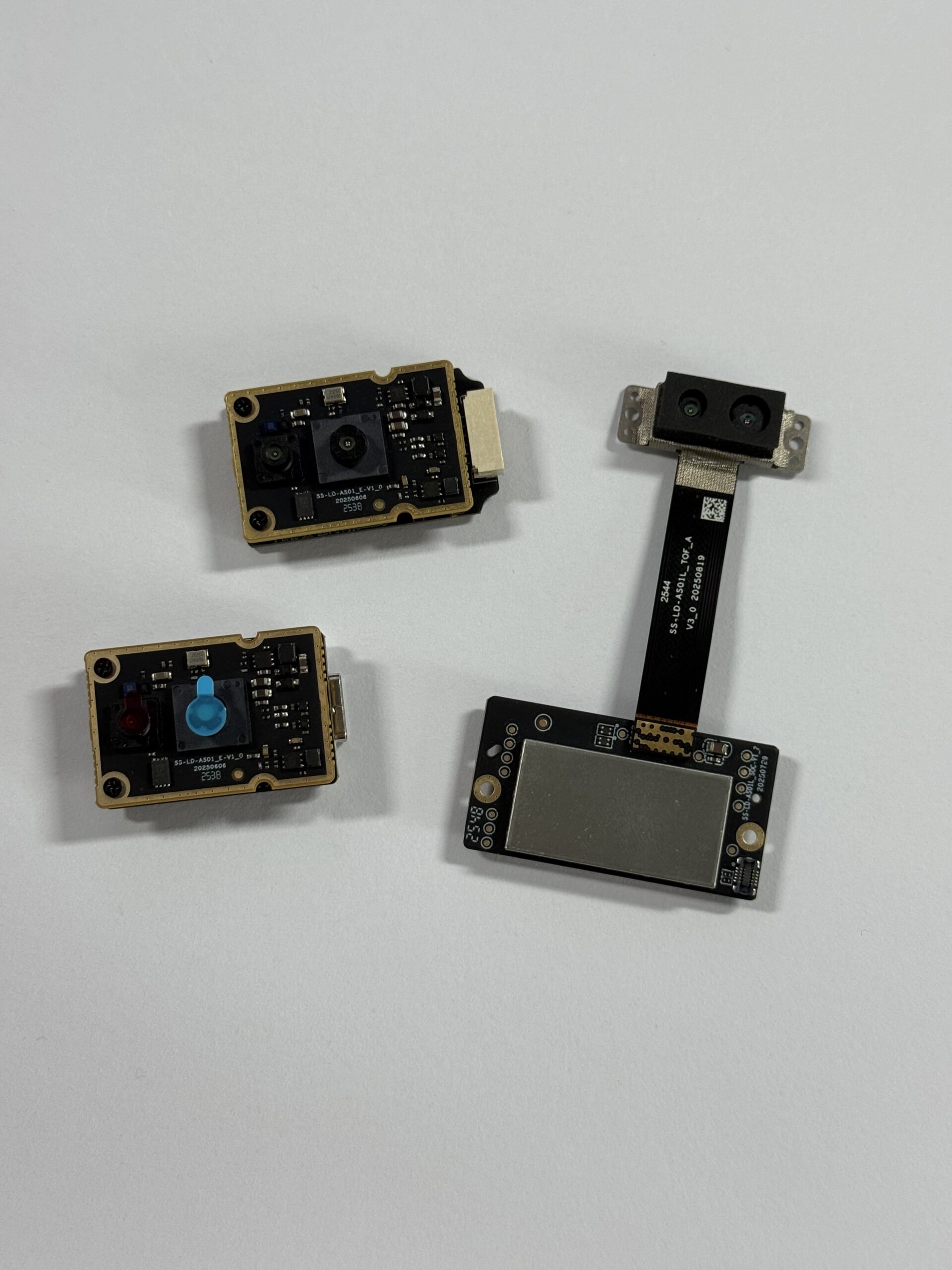
The DTOF Solid state LiDAR HM-LD1 is a compact SPAD dToF LiDAR module designed for real-time depth images and 3D point cloud data in robotics, UAVs, embedded vision, obstacle avoidance, smart inspection, distance detection, and autonomous navigation. It is positioned for engineers and developers who need practical perception hardware for compact systems rather than vague countermeasure products. The module supports use cases including UAV altitude hold, terrain following, robot navigation, obstacle avoidance, SLAM support, autofocus, user presence detection, object recognition, volume measurement, and zone intrusion monitoring.
For buyers researching lidar jammer because of interference concerns, the stronger procurement path is to evaluate a documented sensor like HM-LD1 against real deployment conditions. Its specifications provide concrete engineering inputs: ranging capability, accuracy, field of view, weight, resolution, frame rate, interface options, operating temperature, power consumption, and SDK support. This makes it easier to estimate integration effort for PCs, Raspberry Pi-class systems, flight controllers, embedded Linux platforms, and robot computers.
| Specification | DTOF Solid State LiDAR HM-LD1 |
|---|---|
| Dimensions | 43.5mm × 30mm × 26.5mm |
| Ranging Capability | Indoor: 0.5–25m; Outdoor: 0.2–8m |
| Ranging Accuracy | ±3cm |
| Field of View | 60° horizontal × 45° vertical |
| Weight | 28g |
| Resolution | 40 × 30 |
| Frame Rate | 10fps |
| Interface | UART / UDP / UVC |
| Operating Temperature | -20 ℃ to 60 ℃ |
| Power Consumption | 1.2 W |
| Development Support | SDKs for x86 Windows, x86 Linux, and arm Linux |
HM-LD1 is strongest where compact size, low weight, practical short-to-medium-range depth sensing, and flexible interfaces matter. It is suitable for robotics development, drones, inspection devices, security systems, embedded depth sensing, obstacle detection, and R&D prototypes. Additional validation is recommended for high-speed autonomy, small-object detection, harsh sunlight, transparent barriers, high-reflectivity targets, multi-sensor fleets, and final enclosure optics.
For a buyer, the appeal is not just one number on a spec sheet. It is the full package: ✅ compact module size, ✅ low listed weight, ✅ low listed power consumption, ✅ multiple interface options, ✅ usable indoor and outdoor range declarations, ✅ SDK coverage across common development platforms, ✅ practical use cases for robotics and embedded sensing. Those are the pieces that help an engineering team move from “interesting part” to “integrated subsystem.”
Download DTOF SSL HM-LD1 Product Brochure
View Product Details & Pricing ➔
Integration Planning for Robots, UAVs, and Embedded Systems
Choosing UART, UDP, or UVC
Interface selection should follow the system architecture. UART is often practical for microcontrollers, embedded control boards, simple distance outputs, and direct control logic. UDP can be useful when the sensor data needs to move across a networked host system or into a higher-throughput processing pipeline. UVC can simplify integration with PCs and camera-compatible software workflows. HM-LD1’s support for UART, UDP, and UVC gives engineers multiple integration paths, which is valuable when moving from prototype to system deployment.
Host platform planning
Host planning should begin before hardware purchase. The sensor may connect to a Windows PC during development, an x86 Linux machine for lab testing, an arm Linux platform for embedded deployment, or a controller in a UAV or robot. HM-LD1 supports SDKs for x86 Windows, x86 Linux, and arm Linux, making it suitable for both prototyping and integration across different operating systems and architectures. Buyers should confirm driver availability, sample code, data format, CPU load, synchronization needs, and compatibility with their perception stack.
Mechanical mounting and data workflow
Mechanical mounting determines whether the sensor can actually see the world described in the specification. Engineers should preserve field-of-view clearance, avoid occlusion from frames or landing gear, select appropriate protective window materials, manage dust and moisture exposure, and isolate vibration where needed. The basic data workflow usually moves from sensor output to driver or SDK, then to depth map or point cloud processing, then to filtering, obstacle zones, perception logic, and navigation or control. Each stage should be tested under realistic load before production deployment.
In the shop, integration usually fails at the seams, not at the headline spec. A sensor may be perfectly capable, but the cable is routed next to a noisy motor drive. Or the housing blocks ten degrees of the field of view. Or the host computer can display data on the bench but drops frames once navigation, logging, and communications are all running at the same time. That is why a LiDAR evaluation should include the whole system, not just the sensor sitting on a clean desk.
A sound integration plan should look something like this: ⚙️ power the module from the actual robot supply, ⚙️ confirm interface communication using the intended cable length, ⚙️ collect data on the target host platform, ⚙️ mount the sensor in the proposed mechanical location, ⚙️ test the final optical window material, ⚙️ validate frame timing under full software load, ⚙️ repeat the test in the lighting and surface conditions expected in production. This is the kind of practical work that separates a lab demo from a field-ready robot.
Industrial Application Scenarios
AMR and AGV obstacle avoidance
Autonomous mobile robots and automated guided vehicles need reliable short-to-medium-range perception for obstacle zones, docking assistance, aisle navigation, pallet approach, human presence detection, and route correction. A compact depth sensor can add useful spatial awareness without the size and complexity of larger scanning systems. For these applications, buyers should evaluate field of view, frame rate, minimum range, stopping distance, mounting height, protective windows, and multi-robot operation.
For AMRs and AGVs, the big mistake is assuming one ideal range number tells the whole story. It does not. A warehouse robot cares about where the sensor is mounted, how fast the robot moves, whether pallets are wrapped in shiny plastic, whether people step into blind spots, and whether other robots are running nearby. If a compact module is used for supplemental obstacle sensing, docking, or presence detection, the validation should match those exact jobs instead of treating the module like a generic all-purpose scanner.
UAV altitude hold and terrain following
UAVs are highly sensitive to weight and power. HM-LD1’s listed 28g weight and 1.2 W power consumption are relevant for drones where payload affects flight distance and endurance. The product description identifies UAV altitude hold and terrain following as supported application areas. Engineers should validate performance over expected surfaces, including concrete, soil, vegetation, roofs, water-adjacent areas, and inspection structures. They should also consider vibration, cable retention, sunlight exposure, landing gear occlusion, and flight controller integration.
Drone work adds its own headaches. Sun angle changes. Surfaces change. Vibration is constant. Cable retention matters more than it does on a bench. A lightweight LiDAR module can be valuable, but only if the mounting protects the optical path and the flight controller receives stable, timely data. For UAV altitude hold, the best test is not a quick hover indoors. The best test is controlled outdoor operation over the surfaces and lighting conditions the drone will actually see.
Smart inspection, security, and embedded devices
The product description mentions bridges, expressways, dams, and other hard-to-approach objects as examples where distance measurement can be useful. Smart inspection systems can use depth sensing for positioning, standoff measurement, obstacle awareness, and safer operation near infrastructure. Security systems can use depth data for zone intrusion monitoring and presence detection. Embedded devices may use the module for autofocus, object recognition support, volume measurement, and user presence detection. In all of these scenarios, buyers should validate the sensor against real surfaces, lighting, enclosure constraints, and processing requirements.
For fixed security or inspection devices, the environment may be less dynamic than a mobile robot, but the details still matter. Protective covers can change optical performance. Outdoor housings can trap heat. Dust, moisture, vibration, glare, and target angle can all reduce data quality. A compact dToF module can be a strong fit when space is tight and the system needs basic depth awareness, but the enclosure and data workflow must be designed around the sensor, not added as an afterthought.
Comparison: Jammer, Detector, and Robotics LiDAR Sensor
| Category | Primary Function | Typical Use Context | Industrial Buyer Relevance | Risk Level |
|---|---|---|---|---|
| LiDAR Jammer | Attempts to interfere with a LiDAR measurement device | Often associated with traffic countermeasures or adversarial interference | Not suitable for legitimate robotics perception procurement | Potential legal, safety, and compliance risk |
| LiDAR Detector | Passively detects laser signals | Usually consumer alerting applications | Does not provide depth maps, point clouds, or robot navigation data | Depends on jurisdiction and use case |
| Robotics LiDAR Sensor | Measures distance and produces depth or spatial data | Robots, drones, AGVs, AMRs, cameras, inspection, security | Directly relevant for obstacle avoidance, SLAM support, navigation, and perception | Compliance-safe when sourced and integrated properly |
Many searches for lidar jammer are terminology mistakes. A buyer troubleshooting outdoor sensing, sunlight tolerance, multi-sensor crosstalk, or inconsistent depth readings should not buy a jammer. The correct path is to select a documented robotics LiDAR sensor and test it under real deployment conditions. A sensor with declared specifications, software support, product documentation, and supplier assistance is much more useful than a device marketed around interference or evasion.
Here’s the deal in buyer language: ✅ if you need depth data, buy a robotics LiDAR sensor; ✅ if you need to know whether a laser signal exists, that is a detector category, not a depth sensor category; ✅ if a product is designed to interfere with another measurement system, treat it as a legal and safety risk, not an industrial sensing solution. Clear categories make better purchase orders, better engineering reviews, and fewer painful surprises later.
Procurement Checklist for B2B Buyers
Technical checklist
Confirm indoor and outdoor range separately. Confirm minimum range and any dead zone. Validate accuracy at the target distance and under the expected lighting conditions. Check field of view against robot geometry. Confirm resolution and frame rate against robot speed and stopping distance. Test dark, glossy, glass, metallic, and reflective surfaces. Verify power budget, thermal behavior, cable routing, and grounding. Confirm whether the module outputs raw depth, filtered depth, point cloud data, or multiple data formats. Test the target host platform under full processing load.
Commercial and integration checklist
Confirm lead time, supply stability, documentation, sample code, SDK availability, technical support, warranty terms, and replacement process. Ask whether customization is available if required. For integration, review the mechanical envelope, mounting points, connector access, cable routing, environmental protection, host compute requirements, driver support, data format, calibration process, and production test plan. If the supplier claims outdoor performance, ask what lux level, target reflectivity, and test setup were used. If robots will operate near other LiDAR modules, ask how the sensor behaves in multi-sensor environments.
A strong B2B checklist should be direct and testable: ⚙️ get the datasheet and mechanical drawing, ⚙️ confirm the exact hardware revision, ⚙️ request SDK and sample data before locking the design, ⚙️ test the interface your production system will use, ⚙️ compare published outdoor range against your lighting conditions, ⚙️ verify supplier support for your operating system and processor architecture, ⚙️ run a small pilot before committing to volume. This approach is not slow. It is how experienced teams avoid buying the wrong hardware twice.
Compare your robot’s sensing requirements with HM-LD1
If your team is evaluating obstacle avoidance, UAV altitude sensing, embedded depth maps, point clouds, or compact outdoor ranging, use the HM-LD1 specifications as a practical baseline for testing.
FAQ: LiDAR Jammer, Interference, and Robotics LiDAR
Is a LiDAR jammer the same as a LiDAR detector or robotics LiDAR sensor?
Are LiDAR jammers legal to buy, install, or use?
What should I buy if my real concern is LiDAR interference, outdoor accuracy, or integration cost?
Can sunlight act like a LiDAR jammer?
What causes LiDAR interference in robots?
Is dToF LiDAR better than a camera for obstacle avoidance?
How should I test a LiDAR module before buying in volume?
What specifications matter most for AMR, AGV, and UAV buyers?
Can a compact LiDAR module support SLAM?
Why do indoor and outdoor LiDAR ranges differ so much?
📚 References & Further Reading
- Industry Standard: Luminar Technologies | Hesai Technology
- Related Guide: DTOF Solid state LiDAR HM-LD1






