


3D LiDAR Drone Guide: How to Choose a Lightweight LiDAR Sensor for UAV Mapping, Obstacle Avoidance, and SLAM
Here’s the deal: a modern 3D LiDAR drone is no longer some exotic, high-dollar tool used only by aerial survey crews with a truck full of support gear. Today, UAV developers, robotics teams, inspection contractors, and industrial engineers are putting compact depth sensors and solid-state LiDAR modules on drones to give them real-time spatial awareness. That means obstacle avoidance, altitude control, terrain following, inspection standoff distance, SLAM, autonomous navigation, and short-range 3D perception are all on the table for smaller UAV platforms.
Look, choosing the wrong drone LiDAR sensor creates problems fast. Too much weight eats flight time. Too much current draw stresses the battery and voltage regulation. A sensor with poor outdoor range may look fine in the lab and then fail on a sunny job site. A narrow field of view can miss hazards. A data interface that does not match your flight controller or companion computer can burn weeks of development time. In the shop, these are the things that separate a clean prototype from a drone that never makes it past bench testing.
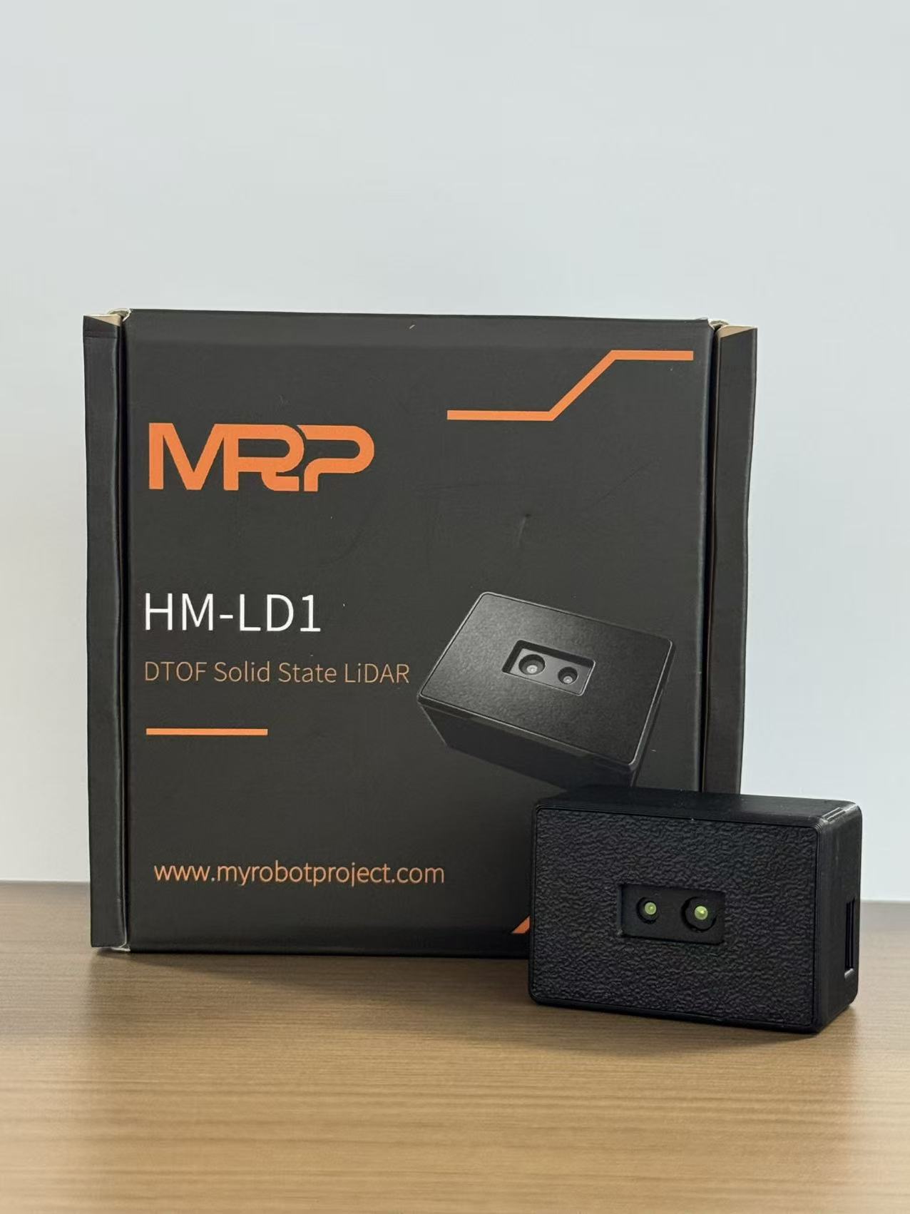
This guide walks through how to choose a lightweight LiDAR sensor for a 3D LiDAR drone, covering the practical engineering points that matter: sensor principles, point cloud output, FOV, ranging accuracy, power, weight, embedded platform support, flight integration, and UAV-specific tradeoffs. It also includes a real product example, the DTOF Solid State LiDAR HM-LD1, a compact 28g SPAD dToF LiDAR module designed for real-time depth images and 3D point cloud output.
By the end, you should have a clear feel for whether your project needs a survey-grade mapping payload, a compact solid-state LiDAR for robotic perception, or a lightweight depth module for UAV obstacle avoidance and SLAM prototyping. The right answer depends less on marketing specs and more on the job the drone actually has to do.
Table of Contents
- 👉 What Is a 3D LiDAR Drone?
- 👉 How 3D LiDAR Works on a Drone
- 👉 Main Applications: Mapping, Obstacle Avoidance, SLAM, and Inspection
- 👉 3D LiDAR Drone Sensor Types Compared
- 👉 How to Choose a Lightweight LiDAR Sensor for UAVs
- 👉 Integration Workflow: From Sensor to Flight Platform
- 👉 Product Example: DTOF Solid State LiDAR HM-LD1
- 👉 3D Mapping vs Obstacle Avoidance: Different Sensor Requirements
- 👉 Using 3D LiDAR for UAV SLAM and Robotic Perception
- 👉 Industrial Buying Checklist for 3D LiDAR Drone Projects
- 👉 FAQ: 3D LiDAR Drone Sensor Selection
What Is a 3D LiDAR Drone?
A 3D LiDAR drone is a UAV equipped with a LiDAR or depth-sensing module that measures distance and generates spatial information in three dimensions. In a complete system, the drone usually includes the flight platform, LiDAR sensor, onboard computer or companion processor, flight controller, positioning system, power distribution, software stack, and mission-planning workflow. The LiDAR may be mounted forward-facing for obstacle avoidance, downward-facing for altitude hold and terrain following, angled for inspection, or integrated into a larger mapping payload with GNSS and IMU.
Not every 3D LiDAR drone is built for centimeter-grade geospatial surveying. That distinction matters. Some systems are designed to create high-density point clouds for mapping deliverables. Others are built to help a UAV avoid a wall, hold height above a surface, navigate indoors, or give a robot a basic 3D view of the world. If you mix those use cases together, you will either overbuy a heavy, expensive payload or underbuy a sensor that cannot support the mission.
Common uses for a 3D LiDAR drone include point cloud mapping, obstacle avoidance, altitude hold, terrain following, autonomous navigation, SLAM, and inspection of bridges, dams, roads, warehouses, power facilities, construction sites, and indoor industrial spaces. For a broader decision framework, see this drone with LiDAR selection guide, which explains how different drone missions affect LiDAR requirements.
The main engineering question is not simply, “Which LiDAR has the longest range?” That is how a lot of projects get sideways. A better question is: “Which sensor gives me the right mix of range, FOV, accuracy, frame rate, weight, power consumption, interface compatibility, SDK support, and environmental performance for this UAV mission?” Answering that correctly can reduce development cost, shorten integration time, and improve flight safety.
How 3D LiDAR Works on a Drone
Time-of-Flight Measurement
LiDAR measures distance by emitting light and analyzing the return signal after it reflects from objects in the environment. In a direct time-of-flight, or dToF, system, the sensor calculates distance by measuring the time it takes for photons to travel from the emitter to the target and back to the receiver. Since light travels at a known speed, that time interval can be converted into distance.
This is useful for UAV perception because the drone gets direct geometry instead of relying only on camera texture, contrast, or lighting. In the field, that can be a big deal. A camera may struggle with a blank wall, a dark warehouse aisle, or a low-texture concrete structure. LiDAR is not magic, but it gives the control system an actual distance measurement it can work with.
SPAD-based dToF LiDAR uses single-photon avalanche diode detection technology to sense returned photons with high timing sensitivity. In practice, the performance of a dToF LiDAR sensor depends on optical design, emitter power, receiver sensitivity, signal processing, target reflectivity, distance, and ambient light conditions. Outdoor sunlight can raise background noise, which is why outdoor range is often lower than indoor or nighttime range. When comparing dToF and iToF technologies, engineers should evaluate range, integration complexity, sunlight robustness, and data output. For a deeper technology comparison, read the dToF vs iToF sensor guide.
From Distance Measurement to Point Cloud
A single distance measurement is useful, but a 3D LiDAR drone usually needs spatial structure. A depth map represents distance values across a two-dimensional field of view, similar to an image where each pixel or measurement cell stores range data. A point cloud converts those depth measurements into 3D coordinates, often represented as X, Y, and Z points in the sensor frame or world frame.
Once the drone has that 3D information, it can detect obstacles, estimate free space, build maps, support local navigation, or feed SLAM algorithms. For a small UAV, the question is how much point cloud detail is needed. You may not need millions of points per second if the job is short-range obstacle avoidance. But you do need reliable geometry at a useful update rate.
For UAVs, LiDAR data is often fused with IMU, GNSS, visual odometry, optical flow, flight controller telemetry, or SLAM algorithms. This fusion is essential when the drone is moving because each LiDAR frame must be interpreted relative to the drone’s position and orientation. If the sensor is mounted at an angle, the software has to account for that orientation. If the drone moves quickly, latency and synchronization become important. If LiDAR data is used for navigation control, the whole processing pipeline must be reliable enough for real-time decisions.
Why Solid-State LiDAR Matters for UAVs
Solid-state LiDAR is attractive for drones because it avoids large rotating assemblies and can be more compact, lightweight, and vibration-resistant. UAV platforms are sensitive to payload mass, center of gravity, and mechanical stability. A heavy scanning LiDAR may work well on a large industrial drone, but it can severely reduce flight time on a compact quadcopter.
A compact solid-state LiDAR module can provide real-time depth output while keeping integration practical for smaller UAVs, mobile robots, embedded platforms, and research prototypes. In the shop, lighter hardware also means simpler brackets, less stress on the airframe, less vibration trouble, and fewer flight-time compromises.
When evaluating a solid-state LiDAR module for a 3D LiDAR drone, engineers should examine frame rate, FOV, output format, range, accuracy, interfaces, SDK support, operating temperature, and power consumption. Interfaces such as UART, UDP, and UVC can significantly affect integration architecture. UART may be useful for flight controllers or microcontrollers, UDP can support networked communication with a companion computer, and UVC can simplify camera-like data capture on PCs and vision processing platforms.
Main Applications: Mapping, Obstacle Avoidance, SLAM, and Inspection
UAV Mapping and 3D Reconstruction
UAV mapping with LiDAR focuses on collecting geometric data from the environment. In high-end applications, this may involve multi-line scanning LiDAR, GNSS, IMU, time synchronization, calibrated mounting, and post-processing software. The output may be a dense point cloud used for topographic mapping, corridor mapping, infrastructure modeling, mining, forestry, or construction progress documentation. For full geospatial survey workflows, manufacturers such as South Survey illustrate the role of professional mapping equipment in survey-grade applications.
That said, not every project needs a professional airborne survey payload. Lightweight modules can be suitable for short-range mapping, object modeling, robotic perception, indoor 3D reconstruction, experimental SLAM, and prototype-level point cloud collection. For example, a research team building a small indoor UAV may care more about low weight and accessible point cloud data than survey-grade absolute accuracy.
Obstacle Avoidance and Collision Prevention
Obstacle avoidance is one of the most practical uses of a drone obstacle avoidance LiDAR. A LiDAR module can help a UAV detect walls, trees, people, machinery, shelves, bridge structures, cables, equipment, or other hazards in its path. For this use case, the sensor does not need to produce a perfect survey map. It needs to detect relevant obstacles early enough for the drone to slow down, stop, reroute, or alert the operator.
For obstacle avoidance, field of view and update rate may be more important than maximum range. A narrow sensor may miss obstacles outside its detection window, while a slow sensor may not update quickly enough for faster flight. Required detection range depends on drone speed, braking distance, control latency, and mission risk. For additional practical guidance, see this drone obstacle avoidance LiDAR guide.
Terrain Following and Altitude Hold
A downward-facing LiDAR sensor can help a drone maintain a stable distance from the ground, roof, crop canopy, road surface, warehouse floor, or inspection target. This is useful in GPS-denied environments, visually difficult conditions, or missions where barometric altitude is not accurate enough relative to the local surface. UAV terrain following can improve inspection consistency, spraying uniformity, low-altitude navigation, and safe operation near uneven surfaces.
For altitude hold, the required sensor depends on expected flight height, surface reflectivity, outdoor lighting, update rate, and integration with the flight controller. A lightweight dToF LiDAR sensor with reliable short-range measurement can be a practical option when the drone needs local distance awareness without carrying a large mapping payload.
SLAM and Autonomous Navigation
LiDAR SLAM allows a UAV to estimate its own movement while building or updating a map of the environment. This is especially valuable in warehouses, tunnels, indoor inspection areas, underground facilities, industrial plants, and other GPS-denied sites. A LiDAR SLAM drone may combine depth or point cloud data with IMU, visual odometry, wheel odometry on ground robots, or optical flow on UAVs.
SLAM does not always require the same sensor as survey mapping. It requires repeatable geometry, sufficient spatial coverage, good timing, and integration with the motion estimation pipeline. A compact depth sensor for drone development can help teams prototype SLAM algorithms without the size, cost, and weight of professional mapping equipment.
Industrial Inspection
Industrial inspection is a strong use case for lightweight 3D sensing. Drones can approach bridges, expressways, dams, warehouses, roofs, industrial tanks, construction sites, power facilities, and security zones. A 3D point cloud drone can support distance measurement, structure awareness, close-range positioning, and collision prevention while the onboard camera captures visual details. In many inspection tasks, the LiDAR supports safety and navigation rather than replacing certified metrology equipment.
3D LiDAR Drone Sensor Types Compared
Mechanical Scanning LiDAR
Mechanical scanning LiDAR uses rotating components or scanning mechanisms to capture a broad field of view. It is commonly used in autonomous vehicles, robotics, mapping, and industrial navigation. Mechanical LiDAR can provide wide coverage and dense point cloud output, depending on the model. For a large UAV mapping platform, this can be an excellent solution.
The disadvantages are usually weight, cost, power consumption, mechanical complexity, and mounting requirements. Small UAVs may not have enough payload margin for a heavier mechanical LiDAR system, especially if the payload also needs GNSS, IMU, vibration isolation, and an onboard computer.
Solid-State LiDAR
Solid-state LiDAR does not rely on a large rotating mechanical assembly, making it attractive for compact UAVs and embedded robotics. A solid-state LiDAR module can be lightweight, lower power, and easier to mount. It may output real-time depth images and 3D point cloud data for obstacle avoidance, terrain following, robotic vision, and SLAM prototyping.
The tradeoff is that compact solid-state modules often have shorter range, smaller FOV, or lower resolution than high-end survey-grade LiDAR systems. For many UAV perception tasks, however, this is acceptable because the goal is not large-area geospatial mapping; the goal is real-time environmental awareness.
2D LiDAR Used for 3D Mapping
A 2D LiDAR can be used to generate 3D point clouds if it is moved through space, tilted, rotated, or fused with drone motion. This approach can work in research projects, but it introduces calibration and synchronization challenges. The system must know the exact pose of each scan line, compensate for motion, and transform measurements into a consistent 3D coordinate frame. Vibration, timing errors, and fast drone movement can distort the resulting map.
Depth Cameras and ToF Modules
Depth cameras and ToF modules provide image-like depth output and can be useful for short-range perception. They are often easy to visualize and integrate into robotic vision pipelines. However, performance depends heavily on outdoor sunlight, reflectivity, range, optics, and the sensor’s depth technology. A compact dToF LiDAR can be a practical bridge between simple proximity sensors and heavy survey-grade payloads, especially for lightweight LiDAR for UAV applications.
| Sensor Type | Strengths | Limitations | Best Fit for 3D LiDAR Drone Projects |
|---|---|---|---|
| Mechanical 3D LiDAR | Wide FOV, dense point cloud, mature mapping use | Higher weight, cost, power, and integration complexity | Survey mapping, industrial inspection, high-end autonomy |
| Solid-State dToF LiDAR | Compact, lightweight, low power, real-time depth output | Usually shorter range and lower resolution than survey systems | Obstacle avoidance, terrain following, SLAM, embedded perception |
| 2D LiDAR with Motion | Lower cost, simple scan profile | Requires motion compensation and pose fusion for 3D output | Research, experimental mapping, controlled indoor robotics |
| Depth Camera / ToF Camera | Rich depth image, easy visualization | Outdoor sunlight and range limitations vary by model | Short-range perception, indoor UAVs, robotic vision |
How to Choose a Lightweight LiDAR Sensor for UAVs
Weight and Payload Budget
Weight is one of the first constraints in any 3D LiDAR drone design. Every gram affects flight endurance, motor loading, battery sizing, center of gravity, vibration behavior, and safety margin. A 28g LiDAR module is much easier to integrate on a compact UAV than a heavy mapping payload. The payload budget should include the sensor, mounting bracket, cable, protective housing, vibration isolation, companion computer, and any extra power electronics.
Engineers should also consider where the sensor is mounted. A forward-facing sensor on the nose of a drone can shift the center of gravity. A downward-facing sensor may require a landing gear modification. An angled inspection sensor may need a rigid mount to prevent misalignment during flight. Lightweight hardware makes these mechanical compromises easier to manage.
Power Consumption
Power draw affects battery life, heat generation, wiring, voltage regulation, and flight reliability. A low-power module can reduce the burden on the UAV’s power distribution system and simplify thermal design. For battery-powered platforms, a 1.2W sensor is easier to support than a high-power payload that requires dedicated regulation and heat management. When calculating power requirements, engineers should account for peak current, startup behavior, cable length, voltage drop, and the power needs of the companion computer.
Ranging Distance
Ranging capability must be evaluated under realistic conditions. Indoor range may be longer because ambient light is controlled. Outdoor range can be shorter because sunlight increases background noise and reduces signal-to-noise ratio. For UAVs used in inspection, agriculture, construction, and outdoor obstacle avoidance, engineers should check outdoor performance rather than relying only on maximum indoor specifications.
For the HM-LD1 example, the listed ranging capability is 0.5–25m indoors and 0.2–8m outdoors. The product description notes accurate measurement from 8 meters outdoors on a clear summer day under approximately 80,000 lux. This makes it useful for short-range inspection, distance detection, and obstacle awareness where the drone is operating near structures such as bridges, expressways, and dams.
Ranging Accuracy
Accuracy requirements depend on the mission. Ranging accuracy of ±3cm can be sufficient for many obstacle avoidance, altitude hold, terrain following, distance detection, and robotic perception tasks. A drone avoiding a wall or maintaining a safe offset from a structure often needs reliable local distance awareness more than certified geospatial accuracy. However, professional surveying may require a complete payload with calibrated GNSS/IMU integration and post-processing workflows.
Field of View
Field of view determines how much space the sensor can observe. A 60° horizontal × 45° vertical FOV provides a useful forward-facing perception window for short-range obstacle detection and navigation assistance. For a drone flying through a corridor, inspecting infrastructure, or detecting objects in front of its path, this type of FOV can be practical. For full 360° mapping or all-around collision avoidance, engineers may need multiple sensors, a scanning system, or a different payload architecture.
Resolution and Frame Rate
Resolution determines spatial detail, while frame rate determines how frequently the UAV receives updated perception data. A sensor with higher resolution can see more structure, but it may require more processing bandwidth. A higher frame rate reduces latency but may increase data handling requirements. The HM-LD1 outputs 40 × 30 resolution at 10fps, which is suitable for lightweight real-time depth perception, embedded development, and prototyping. For high-speed flight, engineers should calculate whether the update rate and detection range provide enough time for safe reaction.
Interface Compatibility
Interfaces can determine how quickly a sensor can be integrated. UART is useful for simple embedded communication and may connect directly to flight controllers or microcontrollers. UDP is useful for networked data transmission to onboard computers. UVC is convenient for PC and vision-based workflows because it can behave like a camera input in many development environments. A sensor that supports multiple interfaces gives developers flexibility to build either a simple control system or a more advanced perception pipeline.
SDK and Development Platform Support
SDK support reduces development cost and integration time. For UAV robotics, support for x86 Windows, x86 Linux, and ARM Linux is valuable because teams may test on a desktop PC, then deploy on Raspberry Pi, embedded Linux boards, or Jetson-class computers. Accessible SDKs also help developers visualize depth maps, capture point clouds, build SLAM pipelines, and connect sensor output to robotics middleware.
Operating Temperature and Environmental Adaptability
Drones may operate in cold warehouses, hot rooftops, outdoor inspection zones, industrial plants, and changing environmental conditions. A sensor operating from -20°C to 60°C gives UAV developers a practical envelope for many industrial and research scenarios. Environmental adaptability should also include vibration, sunlight, reflectivity, dust exposure, mounting protection, and cable reliability.
Need a Lightweight LiDAR Sensor for UAV Development?
Explore the 28g DTOF Solid State LiDAR HM-LD1 for drone obstacle avoidance, terrain following, SLAM prototyping, and embedded 3D perception.
Integration Workflow: From Sensor to Flight Platform
Step 1 — Define the Drone Mission
Before selecting hardware, define the mission. A UAV used for mapping has different requirements from a drone used for obstacle avoidance or altitude hold. Mapping may require dense point clouds and precise positioning. Obstacle avoidance prioritizes low latency and reliable short-range detection. Terrain following requires stable downward distance measurement. SLAM requires repeatable features, frame synchronization, and integration with motion estimation.
Step 2 — Select Sensor Orientation
Sensor orientation should match the detection task. Forward-facing LiDAR is used for obstacle avoidance and navigation. Downward-facing LiDAR supports altitude hold, landing assistance, and terrain following. Angled LiDAR may be useful for bridge inspection, facade inspection, or monitoring structures from a safe offset. Multi-sensor layouts can expand coverage, but they increase weight, cabling, calibration complexity, and processing load.
Step 3 — Connect to Flight Controller or Companion Computer
There are several integration architectures. In a simple system, the LiDAR connects to a flight controller through UART and provides distance or simplified depth information. In a more advanced system, the LiDAR connects to a companion computer through UDP or UVC. The companion computer processes depth maps or point clouds, performs filtering and obstacle segmentation, and sends navigation constraints or velocity commands to the flight controller.
Step 4 — Calibrate Coordinate Frames
Coordinate calibration is essential. The software must understand the relationship between the LiDAR sensor frame, drone body frame, IMU frame, camera frame, and world frame. A small mounting angle error can cause the system to misinterpret an obstacle’s position. For SLAM or mapping, incorrect coordinate transforms can distort the map. For obstacle avoidance, incorrect mounting parameters can cause poor navigation decisions.
Step 5 — Process Depth Map and Point Cloud
Common processing steps include removing invalid points, applying depth thresholds, filtering noise, segmenting obstacles, detecting ground planes, generating occupancy grids, downsampling point clouds, and extracting features for SLAM. For embedded systems, engineers must balance algorithm complexity with available CPU, GPU, memory, and power. A depth map may be sufficient for simple obstacle detection, while a point cloud is more useful for 3D mapping and localization.
Step 6 — Test in Controlled Environments
Testing should progress gradually. Start with a bench test to confirm power, interface, and data output. Then test on a static mount to evaluate FOV, range, and depth stability. Next, test on a tethered drone or low-risk platform. After that, move to low-speed indoor flight and controlled outdoor testing under different lighting conditions. Finally, validate fail-safe behavior, including what happens when the sensor loses data, detects a false obstacle, or operates near its maximum range.
Product Example: DTOF Solid State LiDAR HM-LD1
The DTOF Solid State LiDAR HM-LD1 is a compact SPAD dToF solid-state LiDAR module designed to output real-time depth images and 3D point cloud data. With a weight of 28g, low 1.2W power consumption, and UART/UDP/UVC interfaces, it is suitable for UAV obstacle avoidance, altitude hold, terrain following, distance detection, robotic navigation, SLAM prototyping, smart inspection, and embedded vision development.
For a lightweight 3D LiDAR drone, the HM-LD1 addresses several practical integration constraints. It is compact enough for drones where payload space is limited, light enough to reduce the impact on flight endurance, and low-power enough for battery-powered systems. Its 60° horizontal × 45° vertical FOV provides a short-range perception window, while 40 × 30 resolution at 10fps supports real-time depth workflows. The module supports SDKs for x86 Windows, x86 Linux, and ARM Linux, enabling development across PCs, Raspberry Pi, embedded Linux systems, and other robotics platforms.

| Specification | DTOF Solid State LiDAR HM-LD1 |
|---|---|
| Product Name | DTOF Solid State LiDAR HM-LD1 – DTOF SSL |
| Technology | SPAD dToF solid-state LiDAR |
| Dimensions | 43.5mm × 30mm × 26.5mm |
| Weight | 28g |
| Indoor Ranging Capability | 0.5–25m |
| Outdoor Ranging Capability | 0.2–8m |
| Ranging Accuracy | ±3cm |
| Field of View | 60° horizontal × 45° vertical |
| Resolution | 40 × 30 |
| Frame Rate | 10fps |
| Interfaces | UART / UDP / UVC |
| Operating Temperature | -20°C to 60°C |
| Power Consumption | 1.2W |
| Output Data | Depth image and 3D point cloud data |
| Development Support | SDKs for x86 Windows, x86 Linux, and ARM Linux |
| Typical Applications | UAV obstacle avoidance, altitude hold, terrain following, SLAM, distance detection, smart inspection, robotic vision |
Download the product brochure: DTOF SSL HM-LD1 Product Brochure
View Product Details & Pricing ➔
Why HM-LD1 Fits Lightweight Drone Development
The HM-LD1 is especially relevant when the UAV project requires embedded 3D perception rather than a heavy survey-grade mapping payload. Its 28g weight helps reduce the payload burden, while 1.2W power consumption supports battery-powered drones and mobile robots. The solid-state structure supports compact integration where mechanical simplicity and vibration tolerance are important. Its 60° × 45° FOV gives the drone a practical sensing area for forward-facing obstacle detection or downward surface awareness.
The module’s UART, UDP, and UVC interfaces provide integration flexibility. A developer can connect the module to a flight controller for simpler sensing, to an onboard computer for point cloud processing, or to a PC for testing and visualization. SDK support for x86 Windows, x86 Linux, and ARM Linux helps reduce development time for research labs, drone OEMs, and robotics companies building custom autonomy stacks.
3D Mapping vs Obstacle Avoidance: Different Sensor Requirements
Mapping Requirements
Mapping applications often prioritize point cloud density, absolute accuracy, GNSS/IMU integration, scan coverage, calibration stability, and post-processing software. A professional UAV mapping LiDAR system may include a high-end LiDAR scanner, inertial navigation, georeferencing, time synchronization, and specialized software. The goal is to produce accurate deliverables such as terrain models, infrastructure scans, or engineering documentation.
A compact LiDAR module can still support short-range 3D reconstruction and research, but it should not be confused with a complete survey payload. If the project requires official measurement documentation or large-area mapping, the system requirements will be much higher than those for obstacle avoidance or embedded perception.
Obstacle Avoidance Requirements
Obstacle avoidance prioritizes low weight, low latency, adequate FOV, reliable short-range detection, real-time depth output, and easy interface to the control system. The drone does not need to generate a perfect survey map; it needs to detect hazards quickly enough to react. In many cases, a compact solid-state dToF LiDAR is more practical than a survey payload because it reduces weight, power consumption, and integration complexity.
SLAM Requirements
SLAM sits between mapping and obstacle avoidance. It requires sufficient spatial features, stable timing, repeatable measurements, and integration with IMU or odometry. A LiDAR SLAM drone may not need survey-grade absolute accuracy, but it does need consistent local geometry. Compact solid-state depth sensors can be useful for indoor navigation, research platforms, warehouse drones, and embedded autonomy development.
| Use Case | Most Important Sensor Factors | Recommended Sensor Direction |
|---|---|---|
| Survey Mapping | High accuracy, dense point cloud, GNSS/IMU integration | Professional UAV LiDAR payload |
| Obstacle Avoidance | Low weight, low latency, FOV, real-time depth | Compact solid-state dToF LiDAR |
| Terrain Following | Reliable range, downward mounting, update rate | Lightweight ToF or LiDAR module |
| SLAM Prototyping | Point cloud output, SDK, embedded support | 3D depth module or solid-state LiDAR |
Using 3D LiDAR for UAV SLAM and Robotic Perception
What LiDAR SLAM Needs
SLAM requires the system to estimate its own position while building or updating a map. In a UAV, this is challenging because the platform moves in six degrees of freedom and can be affected by vibration, airflow, lighting changes, and rapid motion. A LiDAR SLAM pipeline usually uses depth or point cloud data together with IMU data, camera input, optical flow, GNSS where available, or flight controller odometry.
The sensor should provide accessible data with stable timing and sufficient environmental structure. The software must transform the LiDAR measurements into the drone body frame, filter noise, identify useful geometry, estimate motion, and update a local or global map. For embedded systems, developers also need to manage CPU load, memory use, and data bandwidth.
Point Cloud Processing Pipeline
A practical point cloud pipeline begins by acquiring a depth frame or point cloud from the sensor. Invalid points are removed, and the data is transformed from the sensor frame to the drone body frame. Filtering may be applied to reduce noise, remove outliers, or downsample the cloud. The system may then extract features, generate an occupancy grid, estimate motion, update a map, and send constraints or commands to the navigation planner.
For obstacle avoidance, the processing may be simpler. The drone may divide the depth map into zones, identify the nearest object in each zone, and apply a safety threshold. For SLAM, the algorithm must preserve enough geometric detail for localization. For mapping, the system must maintain accurate coordinate transforms and time synchronization.
Why Lightweight Sensors Are Useful for SLAM Research
Research labs and development teams benefit from lightweight sensors because they can mount them on small drones, mobile robots, test rigs, and embedded systems without rebuilding the entire platform. A compact embedded LiDAR module reduces mechanical burden and allows teams to test algorithms more frequently. SDK availability for Windows, Linux, and ARM Linux reduces the barrier to experimentation and supports a smoother transition from bench testing to flight testing.
ROS and Embedded Development Considerations
Even when ROS integration is implemented by the developer, the sensor should provide accessible data formats and practical interfaces. UDP and UVC are useful for higher-level processing and visualization, while UART may be useful for simpler embedded ranging tasks. Developers should confirm timestamp handling, coordinate conventions, output units, data rate, and example code before committing to a sensor for a production UAV platform.
Industrial Buying Checklist for 3D LiDAR Drone Projects
Use the following checklist when selecting a drone mapping sensor, drone obstacle avoidance LiDAR, or embedded LiDAR module for UAV development. The best sensor is not always the one with the longest range or highest resolution. It is the one that fits the mission, platform, software architecture, and operating environment.
- ✅ Mission: Is the drone used for mapping, obstacle avoidance, SLAM, inspection, or altitude hold?
- ✅ Weight: Can the UAV carry the LiDAR without reducing flight time below the requirement?
- ✅ Power: Is the power draw compatible with the UAV battery and power distribution system?
- ✅ Range: Does the sensor meet indoor and outdoor range requirements?
- ✅ Accuracy: Is the ranging accuracy sufficient for the application?
- ✅ FOV: Does the sensor cover the required detection zone?
- ✅ Frame Rate: Is the update rate sufficient for the drone’s flight speed?
- ✅ Interfaces: Does the sensor support UART, UDP, UVC, or other required interfaces?
- ✅ SDK: Are development tools available for Windows, Linux, and ARM Linux?
- ✅ Mechanical Integration: Can the sensor be mounted securely with correct orientation and vibration isolation?
- ✅ Environmental Conditions: Can the sensor operate in expected temperature and lighting conditions?
- ✅ Support: Does the supplier provide integration support, documentation, and customization options?
Drone OEMs, robotics developers, and industrial inspection teams should also evaluate the supplier. Strong suppliers typically provide in-house R&D, stable production capability, OEM/ODM customization, technical support, SDK documentation, and practical experience in perception and positioning modules for robots and UAVs. These factors can be as important as the hardware specification because integration support often determines how quickly a prototype becomes a reliable field system.
Build Your 3D LiDAR Drone With Compact dToF Sensing
Contact MRP for LiDAR module integration support, SDK resources, and OEM/ODM customization for UAV and robotics projects.
FAQ: 3D LiDAR Drone Sensor Selection
Can beginners build a 3D LiDAR drone without expensive survey-grade equipment?
Can I create 3D mapping with a 2D LiDAR on a drone?
What matters most when selecting a 3D LiDAR drone sensor?
Is a lightweight 3D LiDAR drone sensor accurate enough for industrial inspection?
What is the difference between a depth map and a point cloud?
Is solid-state LiDAR better than mechanical LiDAR for drones?
How much LiDAR range does a drone need?
Can a 3D LiDAR drone work indoors without GPS?
📚 References & Further Reading
- Industry Standard: South Survey
- Related Guide: Drone with LiDAR selection guide


