


Small LiDAR Drone Guide: Lightweight dToF Sensors for UAV Obstacle Avoidance, Mapping & Custom Builds
Building a small LiDAR drone is not just an industrial UAV problem anymore. Years ago, if you said “LiDAR drone,” most folks pictured a big survey aircraft carrying an expensive scanner, GNSS gear, an IMU, and a payload bracket that looked like it belonged on a production line. That still exists, and it has its place. But here’s the deal: a lot of modern drone builders do not need a full survey payload. They need a compact sensor that gives the aircraft real-time awareness without killing flight time, overloading the frame, or turning a weekend prototype into a six-month integration headache.
For compact UAVs, robotics platforms, and custom drone prototypes, the real challenge is choosing a LiDAR sensor that is light enough to fly, efficient enough for battery-powered systems, and open enough to connect with embedded computers or flight controllers. Instead of treating LiDAR only as a surveying tool, more UAV developers are using compact direct time-of-flight modules for obstacle detection, altitude assistance, terrain awareness, inspection work, mapping experiments, and autonomous navigation development.
Table of Contents
- 👉 What Is a Small LiDAR Drone?
- 👉 Why Lightweight LiDAR Matters for Small UAVs
- 👉 How dToF LiDAR Works on Compact Drone Platforms
- 👉 Small LiDAR Drone Use Cases
- 👉 Mapping LiDAR vs Obstacle Avoidance LiDAR: What Is the Difference?
- 👉 Key Specifications to Compare Before Buying a Small LiDAR Drone Sensor
- 👉 Integration Architecture for a Custom Small LiDAR Drone
- 👉 Recommended Lightweight dToF LiDAR Module for Small Drone Builds
- 👉 Small LiDAR Drone Selection Checklist
- 👉 Implementation Workflow for Developers
- 👉 Common Mistakes When Building a Small LiDAR Drone
- 👉 Small LiDAR Drone FAQ
What Is a Small LiDAR Drone?
A small LiDAR drone is a compact UAV equipped with a LiDAR sensor for depth perception, distance measurement, obstacle detection, terrain awareness, inspection, mapping experimentation, or autonomous navigation research. The term covers several different machines. It might mean a mini indoor drone using a lightweight front sensor to avoid walls, a custom quadcopter carrying a downward-facing distance module for altitude help, or a research UAV collecting depth frames and point clouds for SLAM development.
Full LiDAR setups are powerful — but often too heavy, too complex, or just …
Look, the important point is simple: not every LiDAR drone is a professional survey-grade mapping system. Many compact UAV projects do not need a heavy scanner, precision GNSS, post-processing workflow, and certified mapping deliverables. They need real-time spatial awareness. For those applications, a small solid-state direct time-of-flight module can be more practical than a large surveying payload because it reduces payload weight, power draw, mechanical complexity, and integration cost.
Small LiDAR Drone vs Professional Survey LiDAR Drone
A professional survey LiDAR drone usually combines a high-end LiDAR scanner, GNSS/RTK or PPK positioning, an IMU, mechanical stabilization, time synchronization, calibration procedures, flight planning, and point cloud processing software. The goal is not only to detect objects. The goal is to generate georeferenced point clouds that can support survey, civil engineering, topography, forestry, construction, mining, or corridor mapping workflows.
A small LiDAR drone for perception development is a different animal. It may use a lightweight dToF LiDAR module, an embedded processor, a flight controller, and a practical software pipeline that converts depth data into obstacle zones or height estimates. Instead of producing survey deliverables, the system is often built to answer immediate flight questions: Is there an obstacle ahead? How far is the ground? Is the landing zone clear? Is there a wall in the side-facing field of view? Is the drone getting too close to a structure during inspection?
Who Needs a Small LiDAR Drone?
Small LiDAR drone projects are common among UAV developers, robotics engineers, university labs, inspection companies, drone startups, SLAM researchers, indoor drone teams, Raspberry Pi builders, Jetson developers, and autonomous navigation teams. These users often need flexible hardware that can connect to different platforms and provide depth maps or point cloud data without forcing them into a full commercial survey payload.
In the shop, the team that succeeds is usually the team that treats LiDAR as part of a whole system, not as a magic box. The sensor has to be mounted correctly, powered cleanly, read reliably, filtered in software, and tested in the environment where the drone will actually fly. For teams that need help evaluating interfaces, SDKs, or integration steps, working with a supplier that offers technical support can reduce UAV development risk. This is especially important when LiDAR data will influence flight behavior, because perception reliability, latency, mounting geometry, and software filtering all affect safe system operation.
Why Lightweight LiDAR Matters for Small UAVs
Weight is one of the most unforgiving constraints in UAV engineering. Every additional gram affects thrust margin, battery endurance, flight stability, vibration behavior, center of gravity, and available payload capacity for other components. A small LiDAR drone may need to carry the sensor, cables, voltage regulation hardware, a companion computer, protective mounting, and sometimes extra cameras or IMUs. If the sensor is too heavy or power-hungry, the drone may become unstable, inefficient, or unable to complete the mission.
Weight Directly Affects Flight Time and Stability
Small UAVs have limited payload capacity. A heavy scanner may work well on a larger industrial platform, but it can sharply reduce flight time on a compact quadcopter. A lightweight module is easier to place near the drone’s center of gravity and less likely to require major frame modifications. It also reduces the load on the motors, which can preserve response authority in wind, during rapid acceleration, or when the drone must brake after detecting an obstacle.
Weight also affects safety margin. A drone carrying a payload close to its limit may technically fly, but that does not mean it has enough reserve thrust for stable control, emergency maneuvers, or battery voltage sag. For small LiDAR drone development, the goal is not simply to lift the sensor. The goal is to keep a practical flight envelope with enough margin to test, tune, and recover when conditions are not perfect.
Power Consumption Matters on Battery-Powered Platforms
Power is the second big constraint. Every watt consumed by sensors and computers is energy that cannot be used for propulsion. A small drone carrying a high-power sensor may see reduced endurance, extra heat, and increased electrical design complexity. Developers must consider whether the power system can supply stable voltage under motor load, whether the regulator can handle continuous operation, and whether electrical noise from the propulsion system may affect sensor communication.
Low-power LiDAR modules are attractive because they let developers add depth perception without heavily compromising battery life. Power also matters during bench testing and indoor development, where stable data acquisition is needed for long experiments, calibration runs, software debugging, and repeated validation tests.
Compact Size Helps with Mounting and Sensor Placement
Mechanical integration is more than finding a flat spot and adding screws. The LiDAR must have an unobstructed field of view, appropriate mounting orientation, reliable cable routing, and vibration-resistant support. A front-facing module is typically used for obstacle detection during forward flight. A downward-facing module can support altitude assistance, landing detection, or terrain awareness. A forward-downward angle may help with low-altitude flight and landing zone evaluation. Side-facing placement can support wall following, corridor navigation, and inspection near industrial structures.
Compact dimensions make it easier to integrate the module into tight airframes, protective housings, or multi-sensor arrays. A smaller package also reduces aerodynamic drag and makes it easier to preserve the drone’s balance. In practical builds, that can be the difference between a sensor that looks good on paper and a sensor that actually survives vibration, takeoff, landing, and repeated field work.
How dToF LiDAR Works on Compact Drone Platforms
Direct time-of-flight LiDAR measures distance by emitting a light pulse and measuring how long it takes for the reflected signal to return to the sensor. Because light travels at a known speed, the sensor can calculate the distance to a target based on that measured time interval. In a depth sensor, multiple sensing elements or pixels can produce a grid of distance measurements, which can then be represented as a depth image or transformed into 3D point cloud data.
For a small LiDAR drone, dToF sensing is useful because it provides active depth measurement. The sensor does not rely only on visual texture or stereo image matching. It can detect distance to surfaces in the field of view and provide structured spatial information for obstacle logic, navigation experiments, inspection assistance, and robotics perception development.
Direct Time-of-Flight vs Other Depth Sensing Methods
dToF LiDAR is one of several depth sensing options. Stereo vision estimates depth by comparing two camera images. It can work well in textured environments, but it may struggle with low-texture walls, repetitive patterns, glare, poor lighting, or scenes where the same visual pattern repeats across a surface. Structured light projects a pattern and measures distortion, but it is often better suited to close-range indoor use. Ultrasonic sensors are inexpensive and simple, but they usually provide limited spatial resolution and can be affected by surface angle or acoustic interference. Radar can offer robust detection in difficult weather or dust, but it may not provide the same compact depth image detail for close-range UAV perception. Monocular vision can support advanced autonomy, but it generally requires more complex algorithms and does not directly measure depth from a single frame.
dToF LiDAR is attractive for compact UAVs because it can provide direct distance measurements in a small package. Developers evaluating optical sensing architectures can also review component-level sensing resources from companies such as AMS Osram, a major supplier in optical and photonic technologies.
SPAD-Based dToF Sensing
SPAD stands for single-photon avalanche diode. A SPAD detector is designed to detect extremely weak photon returns, which is useful when measuring reflected light from targets at a distance. In compact dToF modules, SPAD-based sensing can help achieve real-time depth measurement in a small form factor. However, performance is not determined by the detector alone. Optics, emitter design, signal processing, target reflectivity, ambient light, temperature, and mechanical integration all influence real-world sensing quality.
For UAV applications, this means bench specifications should always be validated on the airframe. Propeller vibration, sunlight, surface reflectivity, mounting angle, and flight speed can change the effective detection range and data reliability. A sensor that looks excellent sitting on a desk may behave differently once it is bolted under a quadcopter with motor noise, vibration, airflow, and shifting sunlight.
Depth Map vs Point Cloud Output
A depth map is a pixel grid where each pixel stores a distance value. It is often convenient for real-time obstacle logic because software can divide the image into regions and identify whether an obstacle exists in the center, left, right, top, or bottom of the field of view. For example, a drone can ignore the sky portion of a forward-tilted frame, watch the center zone for direct collision risk, and use side zones to decide whether there is room to move laterally.
A point cloud represents measured points in 3D space, which is useful for visualization, mapping experiments, spatial analysis, and robotics research. Small drone developers may use both formats. A depth map can drive fast safety-zone logic, while point cloud data can be logged for analysis, debugging, or SLAM development. The best format depends on the application and the available processing resources.
Small LiDAR Drone Use Cases
A small LiDAR drone can be used in many applications where the UAV needs to understand nearby surfaces. The sensor does not need to produce a professional mapping deliverable to be useful. In many cases, the value comes from real-time awareness and reliable distance data in a compact format.
Obstacle Avoidance for Compact UAVs
Obstacle avoidance is one of the most common uses for lightweight LiDAR. A forward-facing module can help detect walls, trees, shelves, machinery, structural beams, racks, door frames, vehicles, and other objects in the flight path. The drone’s software can define warning zones and stop zones based on the depth frame. When an object enters a defined safety area, the system can warn the operator, slow the drone, stop forward motion, or command a controlled avoidance behavior depending on the control architecture.
Small solid-state modules are particularly useful when the drone cannot carry a mechanical scanner. They can provide practical spatial coverage while keeping the payload simple and lightweight. Look at the job realistically: if the drone is moving slowly through a warehouse aisle, near a bridge structure, or inside a test lab, a compact depth sensor can provide enough information to support conservative obstacle awareness without turning the airframe into a survey rig.
Altitude Assistance and Terrain Awareness
A downward-facing dToF LiDAR can help estimate relative distance to the ground, floor, roof, bridge deck, conveyor surface, or inspection target. This can support altitude assistance, terrain awareness, landing behavior, or low-level inspection. In some UAV systems, the LiDAR output can complement barometric altitude, optical flow, or visual-inertial estimates.
For terrain following, the integration must consider frame rate, aircraft speed, sensor angle, control loop response, and the roughness of the surface below. A flat concrete floor is one thing. A sloped roof, grass, gravel, machinery, or a bridge truss is another. The control logic should be designed around the surfaces the drone will actually see, not only around a clean lab measurement.
Indoor Navigation and Robotics Research
Indoor flight is difficult because GNSS is unavailable and the drone must navigate around walls, shelves, furniture, machinery, and people. LiDAR can provide depth data for obstacle detection, SLAM research, autonomous flight experiments, and robotics navigation. Indoor environments often have lower sunlight interference than outdoor scenes, which can improve effective ranging for optical sensors.
For teams combining LiDAR with visual-inertial systems, this guide on how to implement ZUPT in VIO provides additional context on inertial correction and localization workflows. Combining LiDAR, cameras, and IMU data can improve robustness compared with relying on a single sensor type. In practice, the best indoor drone systems usually use layers of sensing rather than betting the whole aircraft on one measurement source.
Inspection of Bridges, Expressways, Dams, and Industrial Sites
Compact LiDAR modules can support inspection workflows where drones approach objects that are difficult or unsafe for people to access, such as bridges, expressways, dams, rooftops, towers, tanks, and industrial machinery. In these missions, LiDAR can help estimate standoff distance, detect nearby surfaces, and support safer approach behavior.
Outdoor inspection performance depends on lighting conditions, target reflectivity, target size, surface angle, and mounting configuration. Strong sunlight can reduce the effective range of optical depth sensors, so developers should test the module under realistic field conditions before relying on it for flight-critical behavior. A glossy tank wall at noon, a dark concrete pier at dusk, and a steel beam with angled surfaces can all produce different ranging behavior.
Mapping Experiments and Point Cloud Development
Lightweight dToF modules can be used for point cloud testing, software development, SLAM experiments, and obstacle map generation. They are useful for learning how depth frames become spatial data and how perception software can interpret nearby objects. However, a compact depth module is not automatically equivalent to a professional survey payload.
Mapping experiments and survey-grade mapping have different requirements, and developers should define the expected output before selecting a sensor. If the goal is to generate a local obstacle map for navigation research, a compact dToF module may be a strong fit. If the goal is centimeter-class georeferenced terrain data for engineering deliverables, the project needs a full positioning, synchronization, calibration, and post-processing stack.
Mapping LiDAR vs Obstacle Avoidance LiDAR: What Is the Difference?
The phrase “LiDAR drone” can create confusion because mapping, obstacle avoidance, inspection, and research all use LiDAR differently. Mapping can mean professional land surveying, 3D modeling, SLAM research, depth map visualization, obstacle map generation, or navigation grid mapping. Each use case has different hardware, software, accuracy, and validation requirements.
Professional Survey Mapping Requires More Than a LiDAR Sensor
Professional survey mapping requires accurate georeferencing. A mapping drone generally needs GNSS/RTK or PPK, an IMU, accurate timing, calibration, flight planning, ground control validation, and post-processing software. The LiDAR scanner is only one part of the system. Without reliable trajectory estimation and calibration, the final point cloud may not meet survey expectations.
If your project requires georeferenced survey data, it is important to understand GNSS terminology and positioning hardware; this article on RTK receptor vs receiver is a useful starting point. Positioning architecture becomes especially important when LiDAR data must be tied to real-world coordinates.
Obstacle Avoidance LiDAR Focuses on Real-Time Perception
Obstacle avoidance LiDAR has different priorities. It needs low latency, adequate field of view, reliable short-to-mid-range detection, embedded data access, lightweight design, and power efficiency. Instead of creating a polished georeferenced point cloud, the software usually needs to determine whether the drone can keep moving safely. The output may be a simple warning, a stop command, a velocity limit, or an avoidance direction.
Here’s the deal from an engineering standpoint: obstacle avoidance does not require the sensor to know where every point is on the planet. It requires the aircraft to know what is close enough to matter right now. That shifts the design priority toward fast perception, conservative thresholds, dependable data access, and simple integration with the flight stack.
When a Lightweight dToF Module Is the Better Choice
A lightweight dToF module is often the better choice for prototype UAVs, indoor drones, robotics labs, close-range inspection, terrain awareness, SLAM experiments, embedded perception systems, and education. These applications benefit from real-time depth information but may not need a heavy professional mapping payload. The lower weight and flexible interfaces can accelerate development and make the system easier to test on small airframes.
There is no shame in choosing a compact perception sensor instead of a survey scanner when the job calls for it. In fact, it is usually better engineering. The right sensor is the one that matches the mission, payload budget, power budget, software skill set, and validation plan.
Key Specifications to Compare Before Buying a Small LiDAR Drone Sensor
Choosing a small LiDAR drone sensor requires more than comparing maximum range. Drone integration is a system-level problem involving mechanics, optics, electronics, communication, software, and flight control. The best sensor for one project may be unsuitable for another if the field of view, frame rate, interface, or mounting constraints do not match the mission.
Weight and Mechanical Dimensions
Weight affects payload capacity, flight time, control margin, and balance. Mechanical dimensions affect enclosure design, mounting brackets, cable routing, and field-of-view clearance. For small UAVs, a compact module is easier to mount rigidly and less likely to interfere with propellers, landing gear, cameras, or battery placement. Vibration isolation may be needed, but the mount should still maintain a stable sensor orientation relative to the drone body.
In the shop, I would rather have a slightly lower-spec sensor that mounts cleanly than a higher-spec sensor that hangs off the front of the drone on a flexible bracket. Mechanical slop becomes data error. Data error becomes bad decisions. Bad decisions become broken props.
Ranging Capability: Indoor vs Outdoor Range
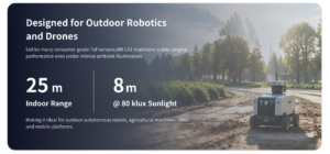
Indoor and outdoor range specifications often differ because sunlight adds optical background noise. A sensor that performs well indoors may have shorter effective range in bright outdoor conditions. Developers should evaluate range under realistic lighting, target reflectivity, and surface angle. For obstacle avoidance, the practical detection distance must also include braking margin and processing latency, not just the published maximum value.
If the drone is moving fast, a long maximum range only helps if the frame rate, processing time, communication path, and control response are all fast enough to use that information. Range is important, but usable range is what matters.
Ranging Accuracy
Accuracy describes how close the measured distance is to the true distance. It is not the same as resolution. Accuracy affects clearance estimation, altitude hold, landing decisions, and obstacle distance thresholds. Real-world accuracy can vary with reflectivity, surface angle, ambient light, filtering, temperature, and vibration. Developers should test accuracy with the types of materials and surfaces expected in the mission.
Field of View
Field of view defines the angular coverage of the sensor. Horizontal FOV determines side-to-side perception width, while vertical FOV determines height coverage. A wider FOV helps obstacle detection because the drone can see more of the scene, but the useful detail also depends on depth resolution. Mounting angle changes how the FOV intersects the environment, so developers should select the sensor orientation based on the application.
For a forward-facing obstacle sensor, a wider horizontal field can help catch objects that are not perfectly centered. For downward sensing, vertical and horizontal coverage determine how much ground area is visible at a given altitude. There is always a tradeoff between coverage, resolution, range, and processing.
Resolution
Depth resolution determines how many measurement points are available in each frame. A 40 × 30 depth frame contains 1,200 distance points per frame. Higher resolution can improve object shape awareness, while lower resolution may still be adequate for zone-based obstacle detection. Developers should match resolution to the required decision logic, processor capability, and data bandwidth.
For many small drones, zone logic is the first practical step. The software does not need to identify a chair, a pipe, and a wall by name. It may only need to know that the center-left portion of the flight path contains a nearby object. That is where a compact depth frame can be very useful.
Frame Rate
Frame rate determines how often new depth data is available. A 10fps sensor provides ten updates per second. Whether that is enough depends on drone speed, stopping distance, control loop design, and safety margins. Slow indoor drones and inspection platforms may not need extremely high frame rates, while fast outdoor drones may require more frequent updates or additional sensing layers.
Frame rate should be judged together with latency. A nominal frame rate is only part of the story. The team also needs to understand how long it takes for the measurement to be captured, transmitted, processed, and converted into a command or warning.
Interfaces: UART, UDP, and UVC
Interface selection affects integration speed. UART is useful for microcontrollers, flight controllers, and embedded control systems that need serial communication. UDP is useful for network-based pipelines and companion computers. UVC is convenient when the LiDAR behaves like a camera-style device connected to a PC or embedded Linux board. Flexible interface support allows developers to prototype quickly and then choose a deployment architecture later.
Look, interface flexibility matters more than many people expect. Early testing may happen on a laptop. The first flight build may use a Raspberry Pi. A later prototype may use Jetson hardware or a flight controller interface. If the LiDAR supports multiple ways to get data out, the development team has room to adapt without replacing the sensor.
Operating Temperature
UAVs may operate in cold storage facilities, outdoor winter conditions, hot rooftops, factories, warehouses, and inspection sites exposed to temperature swings. Operating temperature matters for reliability and long-term product development. Engineers should verify whether the sensor’s temperature range matches the intended mission and whether enclosure design may trap heat.
SDK and Platform Support
SDK support reduces development time. Windows support can help with early visualization and debugging. Linux support is important for robotics systems and deployment. ARM Linux support is especially valuable for embedded platforms such as Raspberry Pi, Jetson, and other companion computers. Good SDK access helps teams acquire depth frames, view point clouds, log data, and integrate perception algorithms with the drone software stack.
A sensor without usable documentation can become an expensive paperweight. Before buying hardware for a serious UAV build, confirm that the development environment, sample tools, data formats, and support channels match what the engineering team can actually use.
Integration Architecture for a Custom Small LiDAR Drone
A custom small LiDAR drone usually includes the LiDAR module, an embedded computer or flight controller, regulated power, software for depth processing, and a control pathway to the autopilot. Some systems also include cameras, IMUs, GNSS, optical flow sensors, or wireless data links. The right architecture depends on whether the LiDAR is used only for operator awareness or actively influences flight behavior.
Basic Hardware Architecture
In a basic architecture, the LiDAR module sends depth data to an embedded computer or flight controller. The processing system filters the depth frame, identifies obstacles or ground distance, and then sends a warning, velocity limit, or control command. For more advanced builds, a companion computer such as a Raspberry Pi or Jetson may process depth maps and point clouds, then communicate with the autopilot through an appropriate control interface.
The power system must provide stable voltage to the LiDAR and processing board. Developers should avoid powering sensitive electronics directly from noisy motor rails without proper regulation and grounding design. Cable strain relief and connector security are also important because vibration can cause intermittent communication failures. Many field issues that look like “bad sensor data” are really loose connectors, poor grounding, weak regulators, or vibration problems.
Choosing the Right Interface for Your Build
UART is usually appropriate when the system needs lightweight serial communication and the data rate fits the application. UDP is useful when depth data is handled by a companion computer or networked system. UVC can simplify early testing because many development platforms can acquire camera-like data streams. A flexible sensor that supports multiple interfaces gives teams room to move from bench testing to flight deployment without changing the sensing hardware.
For a quick proof of concept, UVC can be convenient because developers can visualize data quickly. For robotics software and companion-computer pipelines, UDP may fit better. For simpler control systems or microcontroller-level designs, UART can be the practical choice. The right answer depends on bandwidth, latency, processor load, physical wiring, and the data format required by the control software.
Mounting Position and Calibration
Mounting position determines what the drone can perceive. A forward-facing sensor supports obstacle detection during forward flight. A downward-facing sensor supports altitude assistance and landing awareness. Side-facing sensors can support inspection and wall following. The module should be mounted rigidly, with clear optical access and minimal propeller occlusion. The sensor’s position and angle should be known relative to the drone body frame so that depth measurements are interpreted correctly.
Calibration becomes important when LiDAR data is fused with cameras, IMU data, or flight controller estimates. Even a small angle error can cause distance interpretation errors, especially for downward or angled mounting. Good mechanical repeatability simplifies software and improves test consistency. If the bracket bends, shifts, or vibrates, the software is working from bad assumptions.
Software Pipeline for Obstacle Detection
A typical software pipeline starts by acquiring a depth frame from the LiDAR. The system filters invalid or noisy points, segments near-field obstacles, defines safety zones, estimates the closest relevant object distance, and sends a warning or control response. Developers may log depth maps and point cloud data during testing to understand failure cases. For flight-critical use, obstacle logic should include conservative margins for latency, braking distance, drone momentum, and sensor uncertainty.
Good obstacle logic is usually boring by design. It should not make dramatic decisions based on one questionable frame. It should filter, confirm, apply thresholds, and respond predictably. That kind of discipline is what keeps prototypes from behaving nicely on the bench and unpredictably in the air.
Recommended Lightweight dToF LiDAR Module for Small Drone Builds
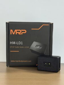
For compact UAV developers, robotics teams, and embedded perception projects, the DTOF Solid State LiDAR HM-LD1 is a lightweight solid-state dToF LiDAR module designed to provide real-time depth images and 3D point cloud data. Its compact size, 28g weight, UART/UDP/UVC interfaces, and SDK support make it suitable for small LiDAR drone prototyping, obstacle detection, altitude assistance, inspection, robotic vision development, and embedded perception projects.

View Product Details & Pricing ➔
The HM-LD1 is based on SPAD dToF technology and is designed to deliver real-time depth images and 3D point cloud data for environmental perception. It supports indoor or nighttime ranging up to 25m and outdoor daytime ranging up to 8m, depending on conditions. This makes it useful for obstacle avoidance, distance detection, autonomous navigation experiments, smart inspection, and robotic vision development. With UVC, UDP, and UART interfaces, it can be integrated with PCs, Raspberry Pi platforms, flight controllers, and embedded systems for both prototyping and deployment.
Industrial LiDAR suppliers such as SICK have helped establish LiDAR as a core sensing technology in automation, safety, and measurement applications. For small UAV developers, the same underlying need for reliable distance perception applies, but the payload, power, and integration constraints are much tighter.
| Specification | DTOF Solid State LiDAR HM-LD1 |
|---|---|
| Product Name | DTOF Solid State LiDAR HM-LD1 |
| Product URL | View Product Page |
| Dimensions | 43.5mm × 30mm × 26.5mm |
| Weight | 28g |
| Ranging Capability | Indoor: 0.5–25m; Outdoor: 0.2–8m |
| Ranging Accuracy | ±3cm |
| Field of View | 60° horizontal × 45° vertical |
| Resolution | 40 × 30 |
| Frame Rate | 10fps |
| Interface | UART / UDP / UVC |
| Operating Temperature | -20℃ to 60℃ |
| Power Consumption | 1.2W |
| Output Data | Depth image and 3D point cloud data |
| SDK Support | x86 Windows, x86 Linux, ARM Linux |
| Brochure | Download DTOF SSL HM-LD1 Product Brochure |
Why HM-LD1 Fits Small LiDAR Drone Development
The HM-LD1 fits small LiDAR drone development because it combines compact mechanical design with usable perception output. At 28g, it is far easier to integrate into a compact UAV than a heavy scanning payload. Its 1.2W power consumption supports battery-powered platforms where endurance and thermal management matter. The 60° horizontal by 45° vertical field of view provides practical spatial coverage for obstacle awareness, while the 40 × 30 resolution supplies 1,200 depth points per frame for depth-map-based logic and point cloud visualization.
The 10fps frame rate can support many development, inspection, and obstacle awareness applications when matched to appropriate drone speed and safety margins. UART, UDP, and UVC interfaces allow integration with embedded controllers, companion computers, and PC-based development environments. SDK support for x86 Windows, x86 Linux, and ARM Linux helps teams move from early testing to embedded deployment more efficiently.
From a practical build standpoint, the HM-LD1 is the kind of module that makes sense when the team wants useful depth data without designing the whole airframe around the sensor. It is small enough to test in different mounting positions, light enough for compact platforms, and open enough to connect into several common development paths.
Best-Fit Applications
- ✅ Small UAV obstacle detection
- ✅ Downward altitude assistance
- ✅ Terrain awareness
- ✅ Indoor drone navigation
- ✅ Robotics SLAM experiments
- ✅ Inspection prototypes
- ✅ Smart security zone detection
- ✅ Object presence sensing
- ✅ Volume and distance measurement
- ✅ Embedded perception development
Need help choosing a lightweight LiDAR module for your UAV or robotics platform? Contact our technical support team for integration guidance, SDK resources, and application recommendations.
Small LiDAR Drone Selection Checklist
A good sensor selection process begins with the mission. A drone designed for indoor obstacle avoidance has different requirements from a drone intended for outdoor inspection or mapping research. Use the checklist below to define the minimum requirements before purchasing hardware.
- ✅ Is the sensor light enough for your drone payload capacity?
- ✅ Does the sensor fit mechanically into your frame or enclosure?
- ✅ Is the indoor and outdoor range suitable for your application?
- ✅ Is the field of view wide enough for obstacle coverage?
- ✅ Is the frame rate adequate for your drone speed?
- ✅ Does the interface match your flight controller or embedded computer?
- ✅ Can your power system support the module continuously?
- ✅ Does the supplier provide SDKs and documentation?
- ✅ Do you need depth maps, point clouds, or simple distance zones?
- ✅ Are you building for obstacle avoidance, mapping, inspection, or research?
For Obstacle Avoidance
For obstacle avoidance, prioritize low weight, useful FOV, real-time depth output, low latency, and stable short-to-mid-range detection. The sensor does not need to create a perfect model of the world, but it must provide reliable enough data for the drone to make conservative movement decisions. Safety zones should be larger than the theoretical stopping distance because processing latency, communication delay, motor response, and sensor uncertainty all add risk.
Look at the full chain: sensor exposure, frame generation, interface transfer, companion-computer processing, autopilot response, motor acceleration, and aircraft momentum. If any part of that chain is slow, the stop zone needs to be larger. That is not pessimism. That is how you keep a prototype from hitting the rack in front of it.
For Mapping Experiments
For mapping experiments, prioritize point cloud access, SDK support, synchronization options, data logging, and calibration workflow. A compact dToF module can help developers learn point cloud processing and spatial perception, but professional georeferenced mapping requires additional positioning and post-processing systems. Define whether the goal is research, visualization, indoor mapping, SLAM, or survey deliverables before selecting the sensor.
For SLAM and local mapping, the sensor data needs to be consistent enough for the algorithm to use. For professional mapping, consistency alone is not enough. The system must also tie the data to a reliable trajectory and coordinate frame. Those are very different engineering problems.
For Commercial UAV Product Development
For commercial UAV product development, prioritize stable supply, documentation, technical support, operating temperature range, mechanical repeatability, and long-term availability. A sensor may work well in a prototype but still be difficult to scale if documentation is incomplete, interface behavior is inconsistent, or the supplier cannot support integration questions. Production teams should evaluate not only the module specifications but also the vendor’s support capability.
Commercial development also requires repeatable assembly. If every aircraft needs a custom bracket adjustment and manual guessing on the sensor angle, that becomes a production problem. Choose hardware and mounting methods that can be repeated, inspected, and tested.
Implementation Workflow for Developers
Building a small LiDAR drone is an iterative engineering process. Teams should start with a clearly defined application, test the sensor on a bench, validate data in a controlled environment, and then move to flight testing with conservative safety limits. The workflow below helps reduce integration risk.
Step 1: Define the Drone Application
Decide whether the LiDAR will support obstacle avoidance, mapping experiments, altitude assistance, terrain following, indoor navigation, inspection, SLAM research, or operator awareness. This decision affects mounting direction, required range, FOV, frame rate, interface, and software logic.
If the mission is unclear, every design decision becomes guesswork. Define the job first. Then pick the sensor, the mounting, and the software architecture that match that job.
Step 2: Choose Sensor Orientation
Forward-facing placement is common for obstacle detection during forward flight. Downward-facing placement supports altitude and landing awareness. Side-facing placement can help with wall following or structural inspection. Multi-directional layouts can improve coverage but add weight, power draw, calibration effort, and processing complexity.
Step 3: Validate Power and Payload Budget
Check the drone’s payload margin, battery capacity, regulated voltage, connector design, and heat dissipation. Confirm that the aircraft can carry the sensor and any companion computer while maintaining stable control. Evaluate flight time impact before committing to a final mechanical design.
In the shop, this is where many builds get into trouble. The sensor might only weigh a few dozen grams, but the complete system includes brackets, cables, regulators, processors, fasteners, protective housing, and sometimes extra batteries. Count all of it.
Step 4: Connect the Interface
Select UART, UDP, or UVC based on the control architecture. UART may be best for compact embedded systems. UDP may be better for companion-computer processing. UVC can simplify desktop and embedded Linux testing. Confirm cable length, connector retention, bandwidth, and latency during bench testing.
Step 5: Acquire Depth Data
Acquire depth frames and point cloud data using the supported SDK or interface. Visualize the data before writing control logic. Test multiple surfaces, including dark materials, reflective objects, angled walls, floors, and outdoor targets. Logging raw data during early tests helps identify failure modes.
Step 6: Build Perception Logic
Develop safety zones such as stop zones, warning zones, clear path zones, ground zones, and ignore zones. Filtering is important because raw depth data may include invalid measurements, edge effects, or noisy returns. The logic should be conservative, especially if it influences flight commands.
A practical obstacle system usually starts simple. First, prove that the drone can detect a wall. Then prove that it can detect the wall while moving. Then prove that it can ignore irrelevant points and respond consistently. Do not jump straight from a bench display to autonomous flight.
Step 7: Test Indoors Before Outdoor Flight
Indoor testing is safer because lighting is controlled, obstacles are predictable, and data logging is easier. Begin with static tests, then handheld motion tests, then tethered or low-speed drone testing if appropriate. Confirm that the system behaves correctly before allowing autonomous responses.
Step 8: Validate Outdoor Range and Reliability
Outdoor validation should include sunlight, target reflectivity, surface angle, drone vibration, environmental conditions, and flight speed. A sensor’s practical detection performance may differ from indoor bench results. Adjust thresholds, safety margins, and filtering based on field data.
- ⚙️ Start with static bench data and confirm basic distance readings.
- ⚙️ Move the sensor by hand and check whether depth frames remain stable.
- ⚙️ Mount the sensor on the airframe and test with motors off.
- ⚙️ Test again with motors running to expose vibration and electrical noise issues.
- ⚙️ Log data during low-speed controlled flight before enabling automatic response.
- ⚙️ Increase speed and complexity only after the data and control response are predictable.
Common Mistakes When Building a Small LiDAR Drone
Small LiDAR drone development becomes much easier when teams avoid common system-level mistakes. Most problems are not caused by the LiDAR specification alone; they come from mismatched expectations, poor mounting, insufficient testing, or underestimating the software required to turn depth data into reliable flight behavior.
Mistake 1: Assuming All LiDAR Sensors Are Survey-Grade
Depth sensors and survey scanners serve different purposes. A compact dToF module can provide useful perception data, but it does not automatically produce professional mapping deliverables. If your goal is certified land surveying, evaluate the complete mapping system.
Mistake 2: Ignoring Payload and Center of Gravity
Even a small sensor can affect balance if mounted far from the center of gravity. Poor placement can reduce stability, increase vibration, and complicate control tuning. Mechanical integration should be considered early in the design.
Mistake 3: Choosing Range Without Considering Sunlight
Outdoor sunlight can reduce effective optical sensing range. Always compare indoor and outdoor specifications and validate performance in realistic lighting. Do not assume maximum indoor range will be available in bright outdoor conditions.
Mistake 4: Focusing Only on Maximum Range
Maximum range is important, but FOV, resolution, frame rate, interface, latency, power consumption, and software access are equally important. A sensor with a shorter range but better integration fit may be more useful for a small drone.
Mistake 5: Underestimating Software Integration
LiDAR provides data, not complete autonomy. Developers must process depth frames, filter invalid points, define decision zones, communicate with the flight controller, and validate behavior under motion. Software integration often takes more time than mechanical mounting.
Mistake 6: Not Planning for Calibration
Coordinate frames matter when LiDAR data influences navigation. The sensor’s position and orientation must be known relative to the drone body frame. Calibration is especially important when fusing LiDAR with cameras, IMUs, optical flow, or GNSS data.
Mistake 7: Testing Only in Perfect Conditions
A drone that works in a bright, clean lab may struggle in a dusty shop, a dim warehouse, a reflective industrial site, or direct sunlight. Test with real surfaces, real lighting, real vibration, and realistic speeds. That is where useful engineering feedback comes from.
Mistake 8: Treating LiDAR as a Safety System Without Validation
LiDAR can support safer flight behavior, but it should not be treated as a certified safety system unless the complete aircraft, software, and validation process are designed for that purpose. For prototypes, always keep conservative limits, manual override, protected test areas, and staged testing procedures.
Small LiDAR Drone FAQ
Is there any LiDAR suitable for small drones?
What should beginners consider before buying a LiDAR drone for mapping or land surveying?
Can I build a custom small LiDAR drone without being locked into a specific UAS brand?
Is a small LiDAR drone good enough for professional mapping?
What is the difference between dToF LiDAR and stereo vision on a drone?
How far can a small drone LiDAR sensor detect obstacles?
Where should LiDAR be mounted on a small drone?
Can a small LiDAR drone fly indoors?
What interfaces are best for connecting LiDAR to a drone?
Does LiDAR replace the need for a camera, IMU, or RTK module on a drone?
Ready to prototype a small LiDAR drone? Explore the DTOF Solid State LiDAR HM-LD1 or download the product brochure to evaluate range, FOV, interfaces, SDK support, and integration fit for your UAV project.
📚 References & Further Reading
- Industry Standard: SICK industrial LiDAR and automation sensing resources
- Industry Standard: AMS Osram optical and photonic sensing resources
- Related Guide: How to implement ZUPT in VIO
- Related Guide: RTK receptor vs receiver
- Related Guide: My Robot Project technical support
- Product Resource: DTOF Solid State LiDAR HM-LD1 product page
- Product Brochure: Download DTOF SSL HM-LD1 Product Brochure


