


Types of Sensors Used in Drones for Collision Avoidance: LiDAR, Vision, Ultrasonic & Radar Compared
Collision avoidance is one of the big practical limits in UAV autonomy. A drone can have a solid flight controller, clean GNSS positioning, a sharp camera, and plenty of motor power, but if it cannot reliably understand what is in front of it, below it, or beside it, it can still fly straight into trees, cables, walls, glass, warehouse racks, machinery, bridge steel, or people walking through the work area.
Here’s the deal: drone collision avoidance is not solved by one magic sensor. It depends on the job. You have to look at sensor type, detection range, field of view, frame rate, latency, weight, power draw, outdoor performance, target material, and the software that turns measurements into safe flight behavior. In the shop, the sensor is only half the story. The rest is mounting, filtering, calibration, flight logic, and testing around real obstacles.
Table of Contents
- 👉 Quick Answer: Best Drone Collision Avoidance Sensors
- 👉 Why Collision Avoidance Sensors Matter in UAV Design
- 👉 Drone Obstacle Avoidance Sensor Comparison Table
- 👉 LiDAR Sensors for Drone Collision Avoidance
- 👉 Vision Sensors: Stereo, Monocular, Depth and SLAM Cameras
- 👉 Ultrasonic Sensors for Close-Range Detection
- 👉 Radar Sensors for Drones
- 👉 Infrared and Time-of-Flight Sensors
- 👉 Optical Flow Sensors for Low-Altitude Stability
- 👉 Thermal Sensors and Specialized Detection
- 👉 Sensor Fusion for Reliable UAV Avoidance
- 👉 How to Choose the Right Sensor for Your Drone
- 👉 Real Product Example: DTOF Solid State LiDAR HM-LD1
- 👉 Integration Workflow for Flight Controllers and Companion Computers
- 👉 Application Scenarios by Drone Type
- 👉 Common Mistakes When Selecting Drone Avoidance Sensors
- 👉 FAQ: Drone Collision Avoidance Sensors
Quick Answer: Best Drone Collision Avoidance Sensors
The most common types of sensors used in drones for collision avoidance are LiDAR sensors, stereo vision cameras, monocular cameras, ultrasonic sensors, infrared and time-of-flight sensors, millimeter-wave radar, optical flow sensors, and thermal sensors. The “best” sensor depends on whether the aircraft is flying indoors or outdoors, how fast it moves, how much payload it can carry, how much power is available, and whether the system needs a single range value, a depth map, a point cloud, velocity data, or object recognition.
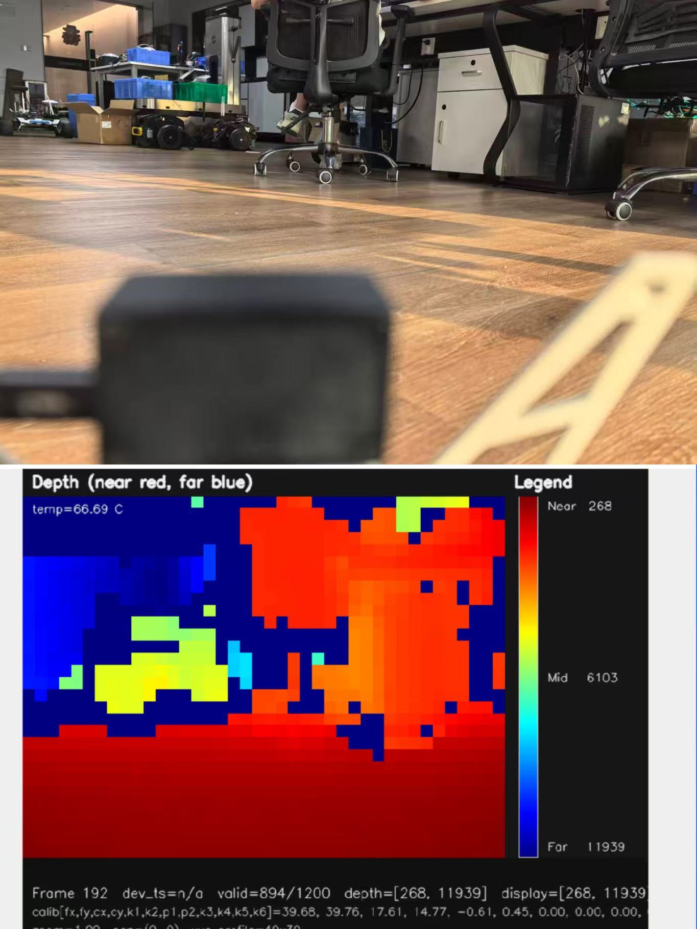
- ✅ LiDAR sensors provide accurate distance measurement, depth maps, and point cloud data for navigation, mapping, terrain following, and obstacle avoidance.
- ✅ Stereo vision cameras estimate depth using two cameras and work well for visual navigation, SLAM, and textured scenes.
- ✅ Monocular vision cameras are light and inexpensive, but need more advanced software to estimate depth and scale.
- ✅ Ultrasonic sensors are cheap short-range sensors often used for landing assistance or slow indoor detection.
- ✅ Infrared and ToF sensors are compact distance sensors used for close-to-mid-range obstacle detection, altitude hold, and embedded perception.
- ✅ Millimeter-wave radar sensors perform well in dust, fog, smoke, rain, darkness, and poor visibility, although their spatial resolution is usually lower than LiDAR or vision.
- ✅ Optical flow sensors help with low-altitude stability and drift reduction, but they are not full 3D collision avoidance sensors.
- ✅ Thermal sensors detect heat signatures and are valuable for inspection and search missions, but they normally supplement geometric sensors rather than replace them.
For small UAVs, a good all-around setup is often a lightweight depth camera or compact solid-state LiDAR paired with onboard processing. For industrial drones, LiDAR plus radar or vision gives more dependable perception in variable environments. For low-cost DIY drones, ultrasonic or infrared sensors can work at low speed and short range, but they are not a great fit for outdoor, high-speed, or cluttered work. For compact UAV projects that need real depth data, take a look at the DTOF Solid State LiDAR HM-LD1.
Why Collision Avoidance Sensors Matter in UAV Design
Collision Avoidance vs. Obstacle Detection vs. Navigation
Look, obstacle detection and collision avoidance are not the same thing. Obstacle detection means the drone has sensed that something exists nearby. Distance measurement means it has estimated how far away that object is. Collision avoidance means the aircraft uses that information to slow down, stop, climb, descend, steer away, or modify a path. Autonomous navigation is broader again: it combines perception, localization, mapping, planning, and control so the drone can complete a mission safely.
A sensor by itself does not “avoid” anything. It provides data: range readings, depth images, camera frames, point clouds, radar targets, thermal images, or optical flow estimates. The flight controller, companion computer, perception stack, and control logic have to turn that data into action. That is where a lot of projects get into trouble. They buy a decent sensor, bolt it to the frame, and expect autonomy. In real systems, you still need filtering, calibration, latency handling, safety margins, and fail-safe behavior.
Why UAVs Are Harder Than Ground Robots
Drones are tougher to protect than ground robots because they move in three-dimensional space and have less time to react. A ground robot can often stop and wait. A UAV has to stay airborne, maintain attitude control, manage wind drift, and avoid creating a new hazard while trying to avoid the first one. A multirotor also has strict payload and power limits. Every gram hurts flight time, and every watt spent on sensors and processors comes out of the battery budget.
UAV sensors also live in a harsh mechanical environment. Propeller wash can disturb ultrasonic sensors. Vibration can hurt camera calibration and depth stability. Sunlight can reduce performance of some optical sensors. Rain, fog, dust, smoke, reflective surfaces, transparent panels, dark materials, low-texture walls, and thin wires can all reduce detection reliability. A drone may need front, rear, side, downward, and upward coverage depending on the mission, and every mounting direction brings its own field-of-view and interference problems.
Key Performance Metrics
When comparing drone obstacle avoidance sensors, engineers should check detection range, minimum range, ranging accuracy, field of view, resolution, frame rate, latency, weight, power consumption, interface compatibility, outdoor performance, environmental robustness, and processing load. A long maximum range is useful, but it does not tell the whole story. A narrow field of view can miss side obstacles. A low frame rate can be too slow for fast flight. A high-resolution sensor can overwhelm a small onboard computer.
Frame rate and latency deserve special attention. If the drone is moving quickly, delayed perception can be as dangerous as no perception. By the time the sensor data is captured, transferred, processed, and acted on, the aircraft may already be too close to the obstacle. Good avoidance design uses speed-dependent thresholds, conservative buffers, and reduced-speed behavior when sensor confidence drops.
Drone Obstacle Avoidance Sensor Comparison Table
The following table compares the major types of sensors used in drones for collision avoidance. This is not a simple winner-takes-all ranking. In the real world, each sensor solves a different part of the UAV perception problem.
| Sensor Type | Best For | Strengths | Limitations | Typical UAV Use |
|---|---|---|---|---|
| LiDAR | Accurate distance and 3D perception | High ranging accuracy, depth data, point cloud output, strong for mapping and obstacle avoidance | Can be affected by reflective, transparent, dark, or absorptive surfaces and severe weather depending on design | Industrial inspection, navigation, SLAM, terrain following, robotic vision |
| Stereo Vision | Depth perception using two cameras | Rich visual information, useful for SLAM, visual odometry, and object recognition | Depends on lighting, calibration, texture, and compute resources | Autonomous drones, research platforms, visual navigation |
| Monocular Vision | Lightweight visual navigation | Low hardware weight, low cost, useful for AI object detection | Depth estimation and scale recovery are algorithmically difficult | AI drones, tracking, landing pad detection, scene classification |
| Ultrasonic | Short-range low-cost sensing | Cheap, simple, low compute, direct distance output | Short range, wide beam, poor angular resolution, affected by wind and acoustic noise | Landing assist, slow indoor drones, educational robotics |
| Infrared/ToF | Compact short-to-mid-range distance sensing | Small, low power, direct distance output, suitable for embedded systems | Can be affected by sunlight, target reflectivity, and field-of-view limits | Close-range avoidance, altitude sensing, landing support |
| Millimeter-Wave Radar | Robust detection in poor visibility | Works in fog, dust, smoke, low light, and can measure relative velocity | Lower spatial resolution than LiDAR or cameras, more complex signal processing | Industrial UAVs, harsh environments, speed-aware obstacle detection |
| Optical Flow | Low-altitude positioning | Useful for hover stability, drift reduction, and GNSS-denied indoor flight | Not a full obstacle avoidance sensor; needs ground texture and lighting | Indoor positioning, landing stabilization, training drones |
| Thermal | Heat signature detection | Works in darkness and detects people, animals, hot equipment, and fire sources | Not ideal for precise geometric depth or primary navigation safety | Search and rescue, inspection, security, firefighting |
LiDAR Sensors for Drone Collision Avoidance
How LiDAR Works
LiDAR measures distance by emitting light and analyzing the reflected return signal. In time-of-flight systems, the sensor estimates distance based on how long it takes light to travel to the target and return. Direct time-of-flight, often called dToF, measures photon travel time directly. Indirect time-of-flight estimates distance from phase shift. Depending on the design, a LiDAR may output a single range value, a depth map, or a three-dimensional point cloud.
Mechanical scanning LiDAR systems rotate or scan a beam to cover a larger area. Solid-state LiDAR uses no large rotating mechanism, which can reduce size, weight, power consumption, and mechanical wear. For drones, compact solid-state LiDAR is attractive because payload weight directly affects flight duration and aircraft handling. Depth maps and point clouds are useful because they let software see the shape and distribution of obstacles instead of relying on one distance reading.
Why LiDAR Is Popular for UAV Avoidance
LiDAR is popular for drone collision avoidance because it provides direct geometric distance data. Unlike a single camera, LiDAR does not need to guess distance only from image features or trained models. That makes it useful for obstacle detection, altitude hold, terrain following, mapping, SLAM, bridge inspection, warehouse flight, and industrial navigation.
LiDAR is also helpful when visual appearance is misleading. A repetitive wall, a dark corner, or a warehouse aisle full of similar shelving can confuse vision algorithms. A depth sensor can still represent nearby surfaces geometrically. That said, LiDAR is not magic. Glass, shiny metal, black absorptive surfaces, strong sunlight, rain, fog, and dust can affect readings depending on the sensor design and environment. For broader context on LiDAR technology and advanced perception ecosystems, see Luminar Technologies.
Solid-State LiDAR vs. Mechanical LiDAR
Mechanical LiDAR can provide wide scanning coverage and dense mapping performance, but these modules are often bigger, heavier, more expensive, and mechanically more complex. They can be excellent for larger mapping drones with enough payload capacity. Solid-state LiDAR is generally easier to mount on compact drones because it has no large rotating assembly. A solid-state module can be mounted forward-facing for obstacle detection, downward-facing for altitude hold and terrain following, or side-facing for wall following and confined-space inspection.
The tradeoff is coverage. A single compact solid-state LiDAR may have a limited field of view. If the drone needs all-around awareness, engineers may use multiple sensors or combine LiDAR with cameras, radar, and software-based motion limits. The right choice should be based on the flight envelope, not just the sensor category printed on the datasheet.
Limitations of LiDAR
LiDAR performance varies by wavelength, optics, detector design, signal processing, power level, and environmental conditions. Highly reflective surfaces may saturate some sensors. Transparent materials such as glass can produce weak or misleading returns. Dark or absorptive materials may reduce signal strength. Rain, fog, dust, and airborne particles can introduce noise or false returns. A narrow field of view can miss obstacles outside the sensing cone, and a low-resolution sensor may not reliably detect thin wires or branches.
Good engineering practice includes filtering noisy depth pixels, rejecting invalid readings, defining conservative safety margins, and validating performance with real obstacles. LiDAR is one of the most useful technologies for UAV collision avoidance, but it works best as part of a complete perception and control system.
Vision Sensors: Stereo, Monocular, Depth and SLAM Cameras
Stereo Vision Cameras
Stereo vision uses two image sensors separated by a known baseline. By comparing the difference between the left and right images, the system estimates depth through disparity. Stereo cameras are common in robotics because they provide both visual context and depth information. They can support visual odometry, SLAM, object detection, landing guidance, and obstacle avoidance in textured environments.
The limitations are lighting, calibration, baseline, texture, and compute load. Stereo cameras need enough visual detail to match image features between two views. A plain white wall, low light, glare, fog, or repetitive warehouse shelving can reduce reliability. The baseline affects usable range: a small baseline is compact but struggles at longer distances, while a larger baseline improves depth estimation but increases size and calibration sensitivity.
Monocular Vision
Monocular vision uses a single camera. It is lightweight, inexpensive, and excellent for recognition tasks such as identifying people, vehicles, landing pads, signs, crops, or inspection targets. The catch is simple: one camera does not directly measure metric depth without extra assumptions, motion, learned models, or scene geometry. That makes monocular vision risky as the only collision avoidance sensor in safety-critical UAV applications.
Monocular systems still have real value when paired with IMU data, visual odometry, AI object detection, or other distance sensors. A camera can classify an obstacle while LiDAR measures the distance to it. In many industrial drones, the camera is both a navigation aid and the main mission payload for inspection, documentation, or remote situational awareness.
RGB-D and Depth Cameras
RGB-D cameras and depth cameras provide depth images using structured light, active stereo, passive stereo, or time-of-flight. They are useful for indoor drones, robotics research, and short-range autonomy. A depth camera can represent an obstacle field as pixels with distance values, which allows perception software to segment near-field hazards and build avoidance zones.
Outdoor performance varies a lot. Some depth cameras are built mainly for indoor lighting and may struggle in strong sunlight. Others are better suited to outdoor use. Engineers should test depth sensors in the actual lighting, reflectivity, vibration, and flight-speed conditions expected in the mission.
SLAM Cameras
SLAM stands for simultaneous localization and mapping. SLAM cameras estimate the drone’s motion while building a map of the environment. They are useful in GNSS-denied areas such as warehouses, tunnels, factories, bridge undersides, and indoor inspection spaces. SLAM usually relies on feature tracking, motion estimation, and IMU fusion. It works best when the environment has enough visual features and when the sensor is properly calibrated and synchronized with the IMU.
SLAM helps with navigation, but it should not be confused with instant collision avoidance. A SLAM map may be sparse, delayed, or incomplete. For reliable avoidance, SLAM output is often combined with real-time depth data from LiDAR, stereo cameras, ToF sensors, or radar.
Ultrasonic Sensors for Close-Range Detection
How Ultrasonic Sensors Work
Ultrasonic sensors emit high-frequency sound waves and measure the time it takes for echoes to return. Because the speed of sound is known, the sensor can estimate distance to a surface. These sensors are simple, inexpensive, and common in educational robotics and low-cost embedded projects.
Where Ultrasonic Sensors Work Well
Ultrasonic sensors work best in controlled, short-range, low-speed applications. They are suitable for low-cost DIY drones, indoor training platforms, landing assistance, educational robotics, and simple downward range sensing. Their low computational requirement makes them easy to connect to microcontrollers or flight controllers.
Limitations on Drones
Ultrasonic sensors have several limitations on UAVs. Their range is short, their beam is wide, and their angular resolution is poor. Wind, propeller noise, acoustic reflections, soft materials, angled surfaces, and multiple nearby ultrasonic sensors can all cause errors. A wide acoustic cone may detect an object without telling the system exactly where it is, which makes precise avoidance difficult.
Recommended Use
Ultrasonic sensors are best treated as secondary or budget-oriented sensors rather than primary collision avoidance sensors for outdoor industrial drones. They are useful for landing support, basic indoor experiments, and slow movement near large surfaces. For serious autonomy, engineers usually move toward LiDAR, depth cameras, radar, or sensor-fusion systems.
Radar Sensors for Drones
How Millimeter-Wave Radar Works
Millimeter-wave radar emits radio waves and analyzes reflected signals to estimate distance, relative velocity, and sometimes angle. Many radar systems use frequency-modulated continuous wave techniques. Radar returns are usually represented as target points or clusters rather than dense visual images.
Radar Advantages
Radar is valuable for drones because it can operate in low light, fog, dust, smoke, and some rain. It can also measure relative velocity through Doppler effects, which helps when detecting moving objects or estimating closing speed. Industrial environments often include dust, steam, glare, and low-texture surfaces, making radar a strong complement to LiDAR and cameras.
For semiconductor-level sensing and imaging components relevant to embedded perception systems, see onsemi.
Radar Limitations
The main limitation of radar is spatial resolution. Compared with LiDAR point clouds or camera images, radar generally provides less detailed shape information. Multipath reflections can complicate interpretation, and small objects such as thin wires may be difficult depending on radar design, range, angle, and signal processing. For UAV collision avoidance, radar is often strongest when fused with LiDAR or vision rather than used alone.
Infrared and Time-of-Flight Sensors
Infrared Proximity Sensors
Infrared proximity sensors emit IR light and detect reflected signals. They are compact, low-cost, and easy to use for short-range detection. Simple IR sensors can detect nearby surfaces, but they are sensitive to sunlight, target reflectivity, surface color, and angle. A dark object may reflect less IR light than a bright object at the same distance, and outdoor lighting can interfere with measurement.
Direct ToF Sensors
Direct time-of-flight sensors measure the actual travel time of emitted light. Depending on the module, a dToF sensor can output a single distance, a depth map, or 3D point cloud data. Direct distance measurement makes ToF sensors more useful for drone perception than simple reflective IR proximity sensors. When implemented as compact solid-state LiDAR, dToF can provide a practical balance of size, power, range, and data richness.
When ToF Is Useful on Drones
ToF sensors are useful for altitude hold, terrain following, landing support, indoor positioning, close-to-mid-range obstacle avoidance, robotic vision, and embedded autonomy. A downward-facing ToF sensor can help a drone maintain height above uneven ground. A front-facing ToF depth module can detect obstacles in a forward corridor. Multiple ToF modules can be used for side or rear coverage where payload allows.
Compact dToF LiDAR modules are becoming popular because they provide direct depth data without large rotating mechanisms. They are especially relevant for small UAVs and robotic platforms where payload, power, and interface simplicity matter.
Optical Flow Sensors for Low-Altitude Stability
What Optical Flow Measures
Optical flow sensors measure the apparent motion of ground texture beneath the drone. By tracking how visual features move between frames, the system can estimate horizontal drift. Optical flow is commonly paired with a downward range sensor because the same apparent pixel motion corresponds to different real-world motion at different altitudes.
Why Optical Flow Is Not Full Collision Avoidance
Optical flow is not usually a full collision avoidance sensor because it is often downward-facing and focused on motion relative to the ground. It does not automatically detect a front wall, side rack, ceiling beam, or moving person. It also requires texture and sufficient lighting. A uniform floor, glossy surface, dust, low light, or rapid altitude changes can reduce accuracy.
Best Use Cases
Optical flow is best for indoor hover, warehouse flight, landing stabilization, low-altitude inspection, and training drones. It is a positioning support technology rather than a complete obstacle avoidance solution. When combined with downward ToF and front-facing depth sensing, it becomes part of a more capable indoor navigation system.
Thermal Sensors and Specialized Detection
What Thermal Sensors Detect
Thermal sensors detect infrared radiation emitted by objects as heat. They do not require visible light, which makes them valuable at night or in visually difficult conditions depending on the sensor and environment. Thermal images can reveal people, animals, hot motors, overheated electrical equipment, fire sources, solar panel defects, and heat leaks.
Where Thermal Helps
Thermal cameras are widely used in search and rescue, firefighting, powerline inspection, solar farm inspection, security monitoring, wildlife detection, and industrial maintenance. A search and rescue drone may use thermal imaging to locate a person in darkness. An inspection drone may use thermal data to identify an overheating electrical component while a visible camera records the asset condition.
Why Thermal Is Usually Supplementary
Thermal sensors usually do not provide precise geometric depth for collision avoidance. They help classify objects and detect heat signatures, but they do not replace LiDAR, radar, stereo vision, or ToF depth sensing for navigation safety. A drone may know that a warm object exists in the scene, but it still needs reliable distance measurement and path planning to avoid collision.
Sensor Fusion for Reliable UAV Avoidance
Why One Sensor Is Not Enough
Every sensor has blind spots. Cameras can struggle with darkness, glare, low texture, or motion blur. LiDAR can be affected by glass, dark surfaces, reflective objects, and severe weather depending on design. Ultrasonic sensors are short-range and vulnerable to acoustic interference. Radar is robust in poor visibility but usually has lower spatial resolution. Thermal cameras detect heat but not precise geometry. Sensor fusion improves reliability by combining complementary strengths.
Common Sensor Fusion Combinations
Common combinations include LiDAR plus camera, stereo vision plus IMU, radar plus LiDAR, optical flow plus downward ToF, GNSS plus IMU plus visual odometry, and LiDAR plus SLAM camera plus flight controller. A front LiDAR may provide distance geometry while a camera classifies the object. A radar may continue detecting obstacles in dust or fog when optical performance degrades. A downward ToF sensor may stabilize altitude while optical flow estimates horizontal drift.
Data Fusion Levels
Sensor fusion can happen at several levels. Raw data fusion combines images, point clouds, radar returns, or depth frames before feature extraction, but it requires accurate calibration and synchronization. Feature-level fusion combines detected edges, landmarks, depth points, object boxes, or target clusters. Decision-level fusion allows each sensor to make an independent detection and then uses voting, prioritization, or confidence scoring. Control-level fusion converts perception outputs into velocity limits, stop commands, steering commands, or trajectory changes.
Latency and Synchronization
Latency and synchronization are critical in drone systems. Each sensor has capture time, processing time, communication delay, and control loop delay. If a LiDAR frame, camera image, IMU sample, and radar target are not correctly timestamped, the system may fuse data from different moments. At low speed this may be acceptable. At higher speeds, it can create unsafe decisions. Engineers should use timestamps, known coordinate frames, calibrated extrinsics, and speed-dependent safety buffers.
How to Choose the Right Sensor for Your Drone
Range Requirements
Detection range should be selected based on drone speed, stopping distance, obstacle type, and processing latency. A slow indoor drone may only need a few meters of detection range. A faster outdoor UAV needs earlier warning and faster processing. Range should not be evaluated only by the maximum number in a datasheet; minimum range, accuracy at useful distances, sunlight performance, and target reflectivity also matter.
Field of View
Field of view determines coverage area. A front-facing sensor with a narrow field of view may miss obstacles during turns or side drift. A downward sensor can support altitude hold but will not protect the drone from a forward wall. Side sensors help with wall following and confined-space inspection. Upward sensors are useful under ceilings, trees, bridges, and industrial structures. Wide coverage often requires multiple sensors or a sensor-fusion architecture.
Payload Weight
Every gram affects flight time. Lightweight solid-state modules are preferred for compact UAVs because they reduce mechanical burden and power demand. Payload weight also affects center of gravity, vibration, motor loading, and maneuverability. A sensor that works well on a large mapping UAV may be unsuitable for a small inspection drone.
Power Consumption
Power consumption affects battery life and thermal design. A 1 to 2 watt perception sensor is easier to integrate into compact UAV systems than a heavier, higher-power perception payload, especially when the drone also carries a companion computer, camera, telemetry radio, and mission payload. Engineers should budget not only sensor power, but also the processing power required to interpret the data.
Output Type
Sensor output type should match the autonomy requirement. A single distance value may be enough for landing support, but it is not enough for complex obstacle avoidance. A depth map provides spatial distance distribution. A point cloud supports geometric mapping and filtering. A camera image supports classification and scene understanding. Radar can provide range and velocity. The correct output depends on whether the drone needs to slow down, stop, steer, map, classify, or plan a path.
Interface Compatibility
Interfaces affect development time. UART is common for embedded microcontrollers and some flight controller range inputs. UDP or Ethernet-style communication can support networked depth or point cloud data. UVC can simplify plug-and-play video or depth streaming to a companion computer. USB and SDK support are valuable for Linux development, ROS workflows, Raspberry Pi, Jetson, and embedded platforms. A technically capable sensor can still be painful to use if the interface does not fit the system architecture.
Environment
Environment is often the deciding factor. Indoor drones may face low light, repetitive textures, glass, and tight spaces. Outdoor drones face sunlight, rain, dust, vegetation, wires, and moving obstacles. Industrial drones may encounter smoke, steam, reflective metal, electromagnetic noise, and confined structures. Agricultural drones may require terrain following over crops, uneven ground, and changing sunlight. Selection should be validated with real flight tests, not only bench measurements.
Real Product Example: DTOF Solid State LiDAR HM-LD1
The DTOF Solid State LiDAR HM-LD1 is a compact SPAD dToF-based LiDAR module designed to deliver real-time depth images and 3D point cloud data. For UAV developers, its main advantages are compact size, low weight, direct ranging output, multiple interfaces, and support for development platforms including x86 Windows, x86 Linux, and Arm Linux. Its combination of depth data, point cloud output, and 28 g weight makes it relevant for drones where payload and power budget directly affect flight time.
Product page: DTOF Solid State LiDAR HM-LD1
| Specification | DTOF Solid State LiDAR HM-LD1 |
|---|---|
| Product Type | Solid-state dToF LiDAR module based on SPAD technology |
| Dimensions | 43.5 mm × 30 mm × 26.5 mm |
| Ranging Capability | Indoor: 0.5–25 m; Outdoor: 0.2–8 m |
| Ranging Accuracy | ±3 cm |
| Field of View | 60° horizontal × 45° vertical |
| Weight | 28 g |
| Resolution | 40 × 30 |
| Frame Rate | 10 fps |
| Interface | UART / UDP / UVC |
| Operating Temperature | -20 ℃ to 60 ℃ |
| Power Consumption | 1.2 W |
| Development Platform Support | SDKs for x86 Windows, x86 Linux, and Arm Linux |
| Typical Applications | UAV altitude hold, terrain following, obstacle avoidance, distance detection, autonomous navigation, robot SLAM, robotic vision development, object recognition, volume measurement, autofocus support, user presence detection, and zone intrusion monitoring |
View Product Details & Pricing ➔
Why HM-LD1 Fits Compact UAV Development
The HM-LD1 fits compact UAV development because it combines small size, low mass, and useful depth output. At 28 g, it is relevant for small drones where payload margin is limited. Its 1.2 W power consumption is suitable for embedded systems compared with many heavier perception payloads. The 60° horizontal by 45° vertical field of view can support front-facing obstacle detection or downward-facing height and terrain perception, depending on mounting orientation.
The module provides a 40 × 30 resolution at 10 fps, which can be used for depth-map and point-cloud-based obstacle analysis. Its UART, UDP, and UVC interfaces give developers multiple integration pathways for flight controllers, PCs, Raspberry Pi-class systems, embedded Linux platforms, and development workstations. The indoor ranging capability of 0.5–25 m supports warehouse, nighttime, indoor inspection, and robotic navigation scenarios. The outdoor daytime range of 0.2–8 m is relevant for close obstacle detection, short-range safety zones, and terrain-related sensing.
Point Cloud and Depth Map Data
The HM-LD1 is designed to provide ranging measurement data that can be displayed as point cloud and depth data. This matters because drones need spatial context, not only a single distance number. A depth map can identify whether an obstacle is centered in the flight path, located near the edge of the field of view, or distributed across the scene. Point cloud data can be filtered, transformed into the drone body frame, and used to build local obstacle maps or safety corridors.
Compact and Lightweight Integration
Compact sensors are important in UAV design because weight affects flight distance, battery life, and responsiveness. The HM-LD1’s compact housing makes it easier to integrate into autonomous mobile robots and drones where space for depth sensors is limited. When evaluating any UAV sensor, engineers should consider not only the module itself, but also mounting brackets, cabling, vibration isolation, power regulation, and processing hardware.
Where to Mount a dToF LiDAR on a Drone
A front-facing HM-LD1-style dToF LiDAR can be used for forward obstacle detection. A downward-facing configuration can support altitude hold, landing support, and terrain following. Side-facing mounting can help with wall following, bridge inspection, warehouse aisle navigation, or confined-space flight. Multiple modules can be arranged for broader coverage when payload and processing resources allow. The sensor should be mounted rigidly, with vibration control if needed, and the field of view should not be blocked by propellers, landing gear, gimbals, or the drone body.
Engineering Notes
Engineers should filter noisy or invalid depth pixels, define minimum safe stopping distance based on drone speed, calibrate sensor extrinsics relative to the drone body frame, and account for field-of-view limitations. Timestamping becomes important when fusing dToF data with IMU, camera, GNSS, optical flow, or radar. The avoidance algorithm should be conservative when confidence is low and should include manual override or fail-safe logic appropriate to the flight platform.
Integration Workflow for Flight Controllers and Companion Computers
Basic Architecture
A typical drone collision avoidance architecture starts with a sensor capturing distance, depth, image, point cloud, radar, or optical flow data. A companion computer or onboard processor filters and interprets that data. The system then generates an obstacle map, safety zone, or nearest-obstacle estimate. Avoidance commands are sent to the flight controller, which modifies velocity, position, attitude, or trajectory commands. The flight controller remains responsible for stable flight, while the perception system provides situational awareness.
Flight Controller Integration
Some simple sensors can be connected directly to a flight controller as rangefinder inputs. More advanced systems may use proximity messages, obstacle distance messages, or higher-level commands through supported communication workflows. The exact implementation depends on the flight stack and hardware. Engineers should avoid sending noisy raw data directly into control behavior without filtering, thresholds, and fail-safe logic. Manual override, maximum speed limits, and conservative stopping behavior should be part of the integration plan.
Companion Computer Integration
More capable drone perception systems usually use a companion computer such as a Raspberry Pi, Jetson, industrial embedded Linux computer, or x86 development platform. The companion computer handles SDK installation, driver communication, depth frame acquisition, image processing, point cloud filtering, ROS node publishing, occupancy grid creation, voxel mapping, and local path planning. Interfaces such as UVC, UDP, UART, USB, and Ethernet-style networking can simplify or complicate integration depending on the sensor and software stack.
Example Avoidance Logic
A practical avoidance algorithm may acquire a depth frame, remove invalid or noisy points, segment the near-field obstacle zone, calculate the minimum distance in the forward corridor, compare that distance against a speed-dependent threshold, and then slow down, stop, climb, descend, or steer. The algorithm should continuously recheck new sensor data and should not assume that a previously clear path remains clear. Moving people, vehicles, branches, hanging cables, and changing terrain require repeated perception updates.
Application Scenarios by Drone Type
DIY Drones
DIY drones often start with ultrasonic or IR sensors because they are inexpensive and easy to wire. These sensors can support basic experiments, slow indoor flight, and landing assist. For more serious autonomy, a compact dToF LiDAR or depth camera is a better long-term choice because it provides richer distance data for ROS, embedded Linux, or custom avoidance logic. A companion computer becomes important when the system needs image processing, point cloud filtering, or local path planning.
Indoor Warehouse Drones
Indoor warehouse drones benefit from optical flow, downward ToF, front-facing depth sensing, and SLAM. Optical flow helps stabilize hover without GNSS. Downward ranging supports altitude control. Front-facing LiDAR or depth vision detects racks, walls, people, and equipment. SLAM cameras or LiDAR-based SLAM can help with localization and mapping. Warehouses often contain repetitive structures, reflective floors, and narrow aisles, so real-site testing is essential.
Industrial Inspection Drones
Industrial inspection drones may need LiDAR for geometry, RGB cameras for visual inspection, thermal cameras for heat detection, and radar for poor visibility or harsh environments. Applications include bridge inspection, power facilities, dams, expressways, factories, and confined industrial assets. In these environments, collision avoidance is not only about protecting the drone; it is also about preventing contact with expensive or hazardous infrastructure.
Agricultural Drones
Agricultural drones often need terrain following, altitude consistency, and obstacle awareness around trees, poles, irrigation structures, and uneven ground. LiDAR or radar can support terrain following, while cameras support crop monitoring and analysis. Downward sensors help maintain consistent altitude over vegetation, improving spraying, imaging, or measurement quality.
Search and Rescue Drones
Search and rescue drones benefit from thermal cameras for detecting people, LiDAR or radar for navigation, and visible cameras for situational awareness. They may fly at night, in smoke, near buildings, over forests, or around unstable structures. Sensor fusion is valuable because no single sensor performs perfectly across all rescue conditions.
Mapping and Surveying Drones
Mapping drones may carry high-grade LiDAR, GNSS, and IMU systems for survey data collection. Collision avoidance sensors may be separate from the mapping payload because the requirements are different. A mapping LiDAR may be optimized for accurate terrain data, while an avoidance sensor may be optimized for real-time safety, low latency, and obstacle proximity detection.
Common Mistakes When Selecting Drone Avoidance Sensors
Choosing Based Only on Maximum Range
Maximum range is only one metric. A sensor with long range but narrow field of view, low frame rate, poor close-range performance, or high latency may not provide safe collision avoidance. Engineers should consider detection reliability at mission-relevant distances, not just the largest number in the datasheet.
Ignoring Drone Speed
A slow sensor may work on a small indoor drone but fail on a fast outdoor UAV. Higher speed requires longer detection distance, lower latency, faster processing, and more conservative safety margins. Stopping distance should include sensor delay, computation delay, flight controller response, braking capability, and wind effects.
Forgetting Environmental Conditions
Sunlight, rain, fog, dust, glass, reflective metal, darkness, vegetation, steam, and low-texture surfaces can change sensor performance. A sensor that works perfectly on a lab bench may fail in a greenhouse, factory, bridge underside, warehouse aisle, or outdoor inspection site. Test in the real mission environment whenever possible.
Treating Detection as Avoidance
Detection is not avoidance. A sensor can report an obstacle, but the drone still needs software logic to decide what to do. The system must define safety zones, stopping thresholds, allowed maneuvers, emergency behavior, and operator override. Avoidance behavior must be tuned to the airframe, speed, flight mode, and mission requirements.
Ignoring Payload and Power Budget
A powerful sensor may be unsuitable if it reduces flight time too much or exceeds payload capacity. Weight, power, cabling, mounting, thermal management, and processing hardware should all be included in the payload budget. Compact solid-state sensors can be attractive when the drone needs meaningful depth data without a heavy mechanical scanning system.
Not Testing Real Obstacles
Drone avoidance systems should be tested with real obstacles such as wires, branches, glass, poles, walls, machinery, warehouse racks, uneven terrain, moving people, reflective surfaces, and dark materials. Thin obstacles are especially difficult. Laboratory testing with flat boards is useful, but it does not prove performance in real collision scenarios.
FAQ: Drone Collision Avoidance Sensors
What is the cheapest effective anti-collision setup for a DIY drone?
Can small drones fit both obstacle avoidance sensors and a good camera?
How do I build computer-vision obstacle avoidance for a flight controller?
Which sensor is best for outdoor drone collision avoidance?
Is LiDAR better than ultrasonic for drone obstacle avoidance?
Do drones need sensors on all sides for collision avoidance?
What is the role of sensor fusion in drone collision avoidance?
What specifications matter most when choosing a drone LiDAR sensor?
Can a drone avoid thin obstacles like wires or branches?
What sensor setup is recommended for indoor drone navigation?
📚 References & Further Reading
- Industry Standard: onsemi | Luminar Technologies
- Related Guide: DTOF Solid State LiDAR HM-LD1 product details and specifications






